Datasheet Fluke Automated AC Measurement Standard. Hubungi PT. Siwali Swantika 021-45850618
•
0 likes•280 views

The 5790A is an automated AC measurement standard designed for demanding calibration applications. It combines the accuracy of a thermal transfer standard with the ease of use of a digital multimeter. Absolute AC voltage measurement uncertainties are as low as ±24 ppm. It covers an AC voltage range of 700μV to 1000V and frequency range of 10Hz to 1MHz. The 5790A uses a patented solid-state thermal RMS sensor and thin-film resistor networks to achieve high accuracy and stability. It can be used as a voltmeter or transfer standard and interfaces with automation software and external equipment.

Recommended
Recommended
More Related Content
What's hot
What's hot (20)
Similar to Datasheet Fluke Automated AC Measurement Standard. Hubungi PT. Siwali Swantika 021-45850618
Similar to Datasheet Fluke Automated AC Measurement Standard. Hubungi PT. Siwali Swantika 021-45850618 (20)
More from PT. Siwali Swantika
More from PT. Siwali Swantika (20)
Recently uploaded
Recently uploaded (20)
Datasheet Fluke Automated AC Measurement Standard. Hubungi PT. Siwali Swantika 021-45850618
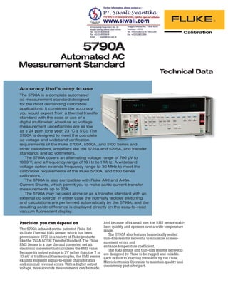
- 1. Technical Data 5790A Automated AC Measurement Standard Accuracy that’s easy to use The 5790A is a complete automated ac measurement standard designed for the most demanding calibration applications. It combines the accuracy you would expect from a thermal transfer standard with the ease of use of a digital multimeter. Absolute ac voltage measurement uncertainties are as low as ± 24 ppm (one year, 23 °C ± 5°C). The 5790A is designed to meet the complete ac voltage and wideband verification requirements of the Fluke 5700A, 5500A, and 5100 Series and other calibrators, amplifiers like the 5725A and 5205A, and transfer standards and ac voltmeters. The 5790A covers an alternating voltage range of 700 μV to 1000 V, and a frequency range of 10 Hz to 1 MHz. A wideband voltage option extends frequency range to 30 MHz to meet the calibration requirements of the Fluke 5700A, and 5100 Series calibrators. The 5790A is also compatible with Fluke A40 and A40A Current Shunts, which permit you to make ac/dc current transfer measurements up to 20A. The 5790A may be used alone or as a transfer standard with an external dc source. In either case the normally tedious switching and calculations are performed automatically by the 5790A, and the resulting ac/dc difference is displayed directly on the easy-to-read vacuum fluorescent display. Precision you can depend on The 5790A is based on the patented Fluke Sol- id-State Thermal RMS Sensor, which has been proven since 1979 in a variety of Fluke products like the 792A AC/DC Transfer Standard. The Fluke RMS Sensor is a true thermal converter, not an electronic converter that calculates the RMS value. Because its output voltage is 2V rather than the 7 to 10 mV of traditional thermocouples, the RMS sensor exhibits excellent signal-to-noise characteristics and minimal reversal errors. With a higher output voltage, more accurate measurements can be made. And because of its small size, the RMS sensor stabi- lizes quickly and operates over a wide temperature range. The 5790A also features hermetically sealed thin-film resistor networks to minimize ac mea- surement errors and enhance temperature coefficient. The RMS sensor and thin-film resistor networks are designed by Fluke to be rugged and reliable. Each is built to exacting standards by the Fluke Microelectronics Operation to maintain quality and consistency part after part.
- 2. 2 Fluke Calibration 5790A Automated AC Measurement Standard Versatility that keeps you productive When you first power up the 5790A, diagnostics verify the instrument’s integrity. The variety of input connections allows you to use the one that best suits your application. There are four sets of input terminals on the 5790A, two Type-N connectors and two sets of five-way binding posts. One Type-N and one set of binding posts are dedicated to the ac measurement and transfer modes. AC or dc voltages may be applied to either input connection over the 5790A’s full range, allowing you to perform automated ac/dc transfer measurements. The 5790A determines automati- cally whether the applied voltage is ac or dc. The second Type-N input connection supports the optional wideband mode, and the second set of binding posts are designed for Fluke A40 Series current shunts. The input connection is selected with the touch of a key on the 5790A front panel. An LED indicates which selection is active. Whether you are using the 5790A as a voltmeter or a transfer standard, input voltage and frequency are always indicated on the measurement display. In the transfer mode, the ac/dc or ac/ac difference is always indicated on the control display in ppm, %, volts or ratio. The 5790A is a fully autoranging instrument and selects the best voltage range for the measurement you are making. You may also select and lock in ranges manually. Robust 1200V input protection is active on all voltage ranges. Using the trigger keys, the 5790A can switch from continuous to single measurements of the input voltage, making it easy to take sample read- ings at predetermined intervals. When using the 5790A in transfer mode, the ref- erence voltage is stored automatically, and all ac/dc or ac/ac difference measurements are made relative to it. At any time, you can view the reference by pressing the VIEW REF key. You may also store the average of two voltages as a reference to eliminate dc reversal errors, for example. The patented Fluke Solid-State RMS Sensor provides the 5790A with exceptional accuracy and stability, and fast settling time. The intuitive front panel layout of the 5790A makes manual operation fast and simple. Keys and selections are logically arranged and labelled. And messages and menus are displayed clearly on the 5790A’s bright, vacuum fluorescent display. The 5790A is at home in automated systems as well. IEEE-488 and RS-232 interfaces are included and all functions of the instruments can be con- trolled by a variety of host computers, including PCs. The 5790A can be integrated into automated systems operating under MET/CALTM Calibration Software. Designed with your support requirements in mind The 5790A provides a self-contained calibration procedure designed to simplify periodic perfor- mance verification. The operator is prompted on what actions to take. To minimize the equipment required, the 5790A is designed to be supported by the Fluke 792A AC/DC Transfer Standard. The 5790A is compatible with Fluke A40 and A40A Current Shunts to permit measurements to 20A. Traceability to national standards for the 5790A is supported through the Fluke 792A. The 5790A is designed to meet the ac verification requirements of the Fluke 5700A Calibrator. Automation using MET/CAL Calibration Software is fast and easy.
- 3. 3 Fluke Calibration 5790A Automated AC Measurement Standard Specifications Absolute Uncertainty Specifications r 5 °C of Calibration Temperature Voltage Range Frequency Range Absolute Uncertainty AC/DC Transfer Mode r ppm 2 Years Measurement Mode r (ppm of Reading + PV) 90 Days 1 Year 2 Years 2.2 mV 10 Hz - 20 Hz 20 Hz- 40 Hz 40 Hz - 20 kHz 20 kHz - 50 kHz 50 kHz - 100 kHz 100 kHz - 300 kHz 300 kHz - 500 kHz 500 kHz - 1 MHz 1700 + 1.3 740 + 1.3 420 + 1.3 810 + 2.0 1200 + 2.5 2300 + 4.0 2400 + 6.0 3200 + 6.0 1700 + 1.3 740 + 1.3 420 + 1.3 810 + 2.0 1200 + 2.5 2300 + 4.0 2400 + 8.0 3500 + 8.0 1700 + 1.3 740 + 1.3 420 + 1.3 820 + 2.0 1200 + 2.5 2300 + 4.0 2600 + 8.0 5000 + 8.0 7 mV 10 Hz - 20 Hz 20 Hz - 40 Hz 40 Hz - 20 kHz 20 kHz - 50 kHz 50 kHz - 100 kHz 100 kHz - 300 kHz 300 kHz - 500 kHz 500 kHz - 1 MHz 850 + 1.3 370 + 1.3 210 + 1.3 400 + 2.0 600 + 2.5 1200 + 4.0 1300 + 6.0 2000 + 6.0 850 + 1.3 370 + 1.3 210 + 1.3 400 + 2.0 600 + 2.5 1200 + 4.0 1300 + 8.0 2300 + 8.0 850 + 1.3 370 + 1.3 210 + 1.3 410 + 2.0 610 + 2.5 1200 + 4.0 1400 + 8.0 3600 + 8.0 22 mV 10 Hz - 20 Hz 20 Hz - 40 Hz 40 Hz - 20 kHz 20 kHz - 50 kHz 50 kHz - 100 kHz 100 kHz - 300 kHz 300 kHz - 500 kHz 500 kHz - 1 MHz 290 + 1.3 180 + 1.3 110 + 1.3 210 + 2.0 310 + 2.5 810 + 4.0 860 + 6.0 1400 + 6.0 290 + 1.3 190 + 1.3 110 + 1.3 210 + 2.0 310 + 2.5 810 + 4.0 890 + 8.0 1700 + 8.0 290 + 1.3 190 + 1.3 110 + 1.3 210 + 2.0 310 + 2.5 820 + 4.0 1000 + 8.0 2600 + 8.0 70 mV 10 Hz - 20 Hz [1] 20 Hz - 40 Hz 40 Hz - 20 kHz 20 kHz - 50 kHz 50 kHz - 100 kHz 100 kHz - 300 kHz 300 kHz - 500 kHz 500 kHz - 1 MHz 240 + 1.5 120 + 1.5 64 + 1.5 120 + 2.0 260 + 2.5 510 + 4.0 660 + 6.0 1100 + 6.0 240 + 1.5 120 + 1.5 65 + 1.5 130 + 2.0 260 + 2.5 510 + 4.0 670 + 8.0 1100 + 8.0 240 + 1.5 130 + 1.5 69 + 1.5 130 + 2.0 260 + 2.5 530 + 4.0 680 + 8.0 1300 + 8.0 220 mV 10 Hz - 20 Hz [1] 210 210 + 1.5 210 + 1.5 210 + 1.5 20 Hz - 40 Hz 82 84 + 1.5 85 + 1.5 87 + 1.5 40 Hz - 20 kHz 34 37 + 1.5 38 + 1.5 43 + 1.5 20 kHz - 50 kHz 67 69 + 2.0 69 + 2.0 73 + 2.0 50 kHz - 100 kHz 160 + 2.5 160 + 2.5 160 + 2.5 100 kHz - 300 kHz 240 + 4.0 250 + 4.0 280 + 4.0 300 kHz - 500 kHz 360 + 6.0 380 + 8.0 400 + 8.0 500 kHz - 1 MHz 940 + 6.0 1000 + 8.0 1200 + 8.0 700 mV 10 Hz - 20 Hz [1] 210 210 + 1.5 210 + 1.5 210 + 1.5 20 Hz - 40 Hz 73 75 + 1.5 76 + 1.5 78 + 1.5 40 Hz - 20 kHz 27 31 + 1.5 33 + 1.5 38 + 1.5 20 kHz - 50 kHz 47 50 + 2.0 51 + 2.0 56 + 2.0 50 kHz - 100 kHz 79 + 2.5 79 + 2.5 84 + 2.5 100 kHz - 300 kHz 160 + 4.0 180 + 4.0 210 + 4.0 300 kHz - 500 kHz 300 + 6.0 300 + 8.0 340 + 8.0 500 kHz - 1 MHz 900 + 6.0 960 + 8.0 1200 + 8.0 [1] For 9.5 to 10 Hz, the specifications is ± (1000 ppm of reading + 1.5 PV)
- 4. 4 Fluke Calibration 5790A Automated AC Measurement Standard Absolute Uncertainty Specifications (cont.) r 5 °C of Calibration Temperature Voltage Range Frequency Range Absolute Uncertainty AC/DC Transfer Mode r ppm 2 Years Measurement Mode r (ppm of Reading) 90 Days 1 Year 2 Years 2.2 V 10 Hz - 20 Hz [2] 200 200 200 200 20 Hz - 40 Hz 63 65 66 69 40 Hz - 20 kHz 18 22 24 29 20 kHz - 50 kHz 43 45 46 52 50 kHz - 100 kHz 70 71 76 100 kHz - 300 kHz 150 160 200 300 kHz - 500 kHz 250 260 310 500 kHz - 1 MHz 840 900 1200 7 V 10 Hz - 20 Hz [2] 200 200 200 200 20 Hz - 40 Hz 63 66 67 70 40 Hz - 20 kHz 18 22 24 29 20 kHz - 50 kHz 44 46 48 53 50 kHz - 100 kHz 80 81 88 100 kHz - 300 kHz 180 190 220 300 kHz - 500 kHz 380 400 470 500 kHz - 1 MHz 1100 1200 1500 22 V 10 Hz - 20 Hz [2] 200 200 200 200 20 Hz - 40 Hz 63 66 67 70 40 Hz - 20 kHz 21 25 27 31 20 kHz - 50 kHz 44 46 48 53 50 kHz - 100 kHz 80 81 85 100 kHz - 300 kHz 180 190 220 300 kHz - 500 kHz 380 400 470 500 kHz - 1 MHz 1100 1200 1500 70 V 10 Hz - 20 Hz [2] 200 200 200 200 20 Hz - 40 Hz 63 67 68 72 40 Hz - 20 kHz 25 30 32 39 20 kHz - 50 kHz 55 56 57 63 50 kHz - 100 kHz 91 94 110 100 kHz - 300 kHz 190 200 220 300 kHz - 500 kHz 400 410 510 500 kHz - 1 MHz 1100 1200 1500 220 V 10 Hz - 20 Hz 200 200 200 200 20 Hz - 40 Hz 63 67 68 72 40 Hz - 20 kHz 23 29 31 38 20 kHz - 50 kHz 63 67 69 77 50 kHz - 100 kHz 96 98 110 100 kHz - 300 kHz 210 210 260 300 kHz - 500 kHz 440 500 700 700 V 10 Hz - 20 Hz 200 200 200 200 20 Hz - 40 Hz 92 96 99 110 40 Hz - 20 kHz 36 39 41 47 20 kHz - 50 kHz 120 130 150 50 kHz - 100 kHz 400 500 850 1000 V 10 Hz - 20 Hz 200 200 200 200 20 Hz - 40 Hz 92 96 99 110 40 Hz - 20 kHz 33 37 38 44 20 kHz - 50 kHz 120 130 150 50 kHz - 100 kHz 400 500 850 [2] For 9.5 to 10 Hz, the specifications is ± (1000 ppm of reading)
- 5. 5 Fluke Calibration 5790A Automated AC Measurement Standard Relative Uncertainty Specifications r 5 qC of Calibration Temperature Voltage Range Frequency Range Relative Uncertainty AC/DC Transfer Mode r ppm 2 Years Measurement Mode r (ppm of Reading + PV) 90 Days 1 Year 2 Years 2.2 mV 10 Hz - 20 Hz 100 + 1.3 110 + 1.3 110 + 1.3 20 Hz - 40 Hz 54 + 1.3 64 + 1.3 68 + 1.3 40 Hz - 20 kHz 44 + 1.3 57 + 1.3 61 + 1.3 20 kHz - 50 kHz 57 + 2.0 67 + 2.0 110 + 2.0 50 kHz - 100 kHz 79 + 2.5 86 + 2.5 120 + 2.5 100 kHz - 300 kHz 190 + 4.0 230 + 4.0 390 + 4.0 300 kHz - 500 kHz 590 + 6.0 720 + 8.0 1200 + 8.0 500 kHz - 1 MHz 2200 + 6.0 2600 + 8.0 4400 + 8.0 7 mV 10 Hz - 20 Hz 80 + 1.3 83 + 1.3 86 + 1.3 20 Hz - 40 Hz 33 + 1.3 39 + 1.3 45 + 1.3 40 Hz - 20 kHz 29 + 1.3 36 + 1.3 42 + 1.3 20 kHz - 50 kHz 40 + 2.0 4 + 2.0 63 + 2.0 50 kHz - 100 kHz 53 + 2.5 57 + 2.5 72 + 2.5 100 kHz - 300 kHz 110 + 4.0 130 + 4.0 210 + 4.0 300 kHz - 500 kHz 370 + 6.0 450 + 8.0 740 + 8.0 500 kHz - 1 MHz 1600 + 6.0 2000 + 8.0 3400 + 8.0 22 mV 10 Hz - 20 Hz 69 + 1.3 72 + 1.3 75 + 1.3 20 Hz - 40 Hz 34 + 1.3 40 + 1.3 46 + 1.3 40 Hz - 20 kHz 30 + 1.3 36 + 1.3 43 + 1.3 20 kHz - 50 kHz 40 + 2.0 45 + 2.0 64 + 2.0 50 kHz - 100 kHz 53 + 2.5 57 + 2.5 73 + 2.5 100 kHz - 300 kHz 97 + 4.0 110 + 4.0 160 + 4.0 300 kHz - 500 kHz 310 + 6.0 380 + 8.0 610 + 8.0 500 kHz - 1 MHz 1200 + 6.0 1500 + 8.0 2500 + 8.0 70 mV 10 Hz - 20 Hz 60 + 1.5 61 + 1.5 62 + 1.5 20 Hz - 40 Hz 27 + 1.5 30 + 1.5 37 + 1.5 40 Hz - 20 kHz 22 + 1.5 25 + 1.5 34 + 1.5 20 kHz - 50 kHz 34 + 2.0 36 + 2.0 44 + 2.0 50 kHz - 100 kHz 53 + 2.5 54 + 2.5 62 + 2.5 100 kHz - 300 kHz 110 + 4.0 120 + 4.0 170 + 4.0 300 kHz - 500 kHz 270 + 6.0 290 + 8.0 320 + 8.0 500 kHz - 1 MHz 910 + 6.0 970 + 8.0 1200 + 8.0 220 mV 10 Hz - 20 Hz 55 60 + 1.5 61 + 1.5 62 + 1.5 20 Hz - 40 Hz 20 27 + 1.5 29 + 1.5 35 + 1.5 40 Hz - 20 kHz 17 22 + 1.5 24 + 1.5 31 + 1.5 20 kHz - 50 kHz 17 22 + 2.0 24 + 2.0 33 + 2.0 50 kHz - 100 kHz 51 + 2.5 52 + 2.5 59 + 2.5 100 kHz - 300 kHz 100 + 4.0 120 + 4.0 170 + 4.0 300 kHz - 500 kHz 260 + 6.0 290 + 8.0 310 + 8.0 500 kHz - 1 MHz 890 + 6.0 950 + 8.0 1200 + 8.0 700 mV 10 Hz - 20 Hz 55 60 + 1.5 61 + 1.5 62 + 1.5 20 Hz - 40 Hz 20 27 + 1.5 29 + 1.5 34 + 1.5 40 Hz - 20 kHz 15 22 + 1.5 24 + 1.5 31 + 1.5 20 kHz - 50 kHz 15 22 + 2.0 24 + 2.0 33 + 2.0 50 kHz - 100 kHz 51 + 2.5 52 + 2.5 59 + 2.5 100 kHz - 300 kHz 100 + 4.0 120 + 4.0 170 + 4.0 300 kHz - 500 kHz 260 + 6.0 270 + 8.0 310 + 8.0 500 kHz - 1 MHz 890 + 6.0 950 + 8.0 1200 + 8.0
- 6. 6 Fluke Calibration 5790A Automated AC Measurement Standard Relative Uncertainty Specifications (cont.) r 5 qC of Calibration Temperature Voltage Range Frequency Range Relative Uncertainty AC/DC Transfer Mode r ppm 2 Years Measurement Mode r (ppm of Reading + PV) 90 Days 1 Year 2 Years 2.2 V 10 Hz - 20 Hz 55 60 61 62 20 Hz - 40 Hz 19 26 28 34 40 Hz - 20 kHz 15 20 22 27 20 kHz - 50 kHz 15 21 23 33 50 kHz - 100 kHz 49 50 57 100 kHz - 300 kHz 92 110 160 300 kHz - 500 kHz 220 230 280 500 kHz - 1 MHz 830 890 1200 7 V 10 Hz - 20 Hz 55 60 61 62 20 Hz - 40 Hz 19 27 29 36 40 Hz - 20 kHz 15 20 22 27 20 kHz - 50 kHz 18 23 26 35 50 kHz - 100 kHz 62 64 73 100 kHz - 300 kHz 140 150 180 300 kHz - 500 kHz 360 380 450 500 kHz - 1 MHz 1100 1200 1500 22 V 10 Hz - 20 Hz 55 60 61 62 20 Hz - 40 Hz 19 28 30 37 40 Hz - 20 kHz 15 20 22 27 20 kHz - 50 kHz 18 23 26 35 50 kHz - 100 kHz 62 64 69 100 kHz - 300 kHz 140 150 180 300 kHz - 500 kHz 360 380 450 500 kHz - 1 MHz 1100 1200 1500 70 V 10 Hz - 20 Hz 55 60 62 63 20 Hz - 40 Hz 19 29 31 39 40 Hz - 20 kHz 15 23 25 34 20 kHz - 50 kHz 22 25 27 39 50 kHz - 100 kHz 64 68 85 100 kHz - 300 kHz 140 150 180 300 kHz - 500 kHz 370 390 490 500 kHz - 1 MHz 1100 1200 1500 220 V 10 Hz - 20 Hz 55 61 62 64 20 Hz - 40 Hz 19 30 32 40 40 Hz - 20 kHz 15 23 25 34 20 kHz - 50 kHz 24 30 34 49 50 kHz - 100 kHz 66 69 83 100 kHz - 300 kHz 160 170 220 300 kHz - 500 kHz 410 480 680 700 V 10 Hz - 20 Hz 55 62 63 65 20 Hz - 40 Hz 19 31 33 41 40 Hz - 20 kHz 19 24 25 31 20 kHz - 50 kHz 100 110 140 50 kHz - 100 kHz 390 500 850 1000 V 10 Hz - 20 Hz 55 62 63 65 20 Hz - 40 Hz 19 31 33 41 40 Hz - 20 kHz 19 24 25 31 20 kHz - 50 kHz 100 110 140 50 kHz - 100 kHz 390 500 850
- 7. 7 Fluke Calibration 5790A Automated AC Measurement Standard Secondary Performance and Operating Characteristics Voltage Range Frequency Range 24 Hour AC Stability r 1 qC Slow Filter Peak- Peak r PV Temperature Coefficient [1] Input Resistance [2]10 qC to 40 qC 0 qC to 10 qC 40 qC to 50 qC ppm / qC 2.2 mV 10 Hz - 20 Hz 0.4 50 50 20 Hz - 40 Hz 0.4 50 50 40 Hz - 20 kHz 0.4 50 50 20 kHz - 50 kHz 0.4 50 50 >10 M: 50 kHz - 100 kHz 0.8 75 75 100 kHz - 300 kHz 1.5 100 100 300 kHz - 500 kHz 3.0 150 150 500 kHz - 1 MHz 4.5 200 200 7 mV 10 Hz - 20 Hz 0.4 15 15 20 Hz - 40 Hz 0.4 15 15 40 Hz - 20 kHz 0.4 15 15 20 kHz - 50 kHz 0.4 15 15 >10 M: 50 kHz - 100 kHz 0.8 25 25 100 kHz - 300 kHz 1.5 60 60 300 kHz - 500 kHz 3.0 80 80 500 kHz - 1 MHz 4.5 125 125 22 mV 10 Hz - 20 Hz 0.4 5 5 20 Hz - 40 Hz 0.4 5 5 40 Hz - 20 kHz 0.4 5 5 20 kHz - 50 kHz 0.4 5 5 >10 M: 50 kHz - 100 kHz 0.8 8 8 100 kHz - 300 kHz 1.5 10 10 300 kHz - 500 kHz 3.0 40 40 500 kHz - 1 MHz 4.5 100 100 r (ppm of Reading) 70 mV 10 Hz - 20 Hz 18 5 5 20 Hz - 40 Hz 18 5 5 40 Hz - 20 kHz 18 5 5 20 kHz - 50 kHz 18 5 5 >10 M: 50 kHz - 100 kHz 24 8 8 100 kHz - 300 kHz 24 10 10 300 kHz - 500 kHz 48 30 30 500 kHz - 1 MHz 150 75 75 220 mV 10 Hz - 20 Hz 12 1.5 3.0 20 Hz - 40 Hz 8 1.5 3.0 40 Hz - 20 kHz 8 1.5 3.0 >10 M: 20 kHz - 50 kHz 8 2.0 3.0 50 kHz - 100 kHz 18 5.0 8.0 100 kHz - 300 kHz 24 10.0 10.0 300 kHz - 500 kHz 36 20.0 20.0 500 kHz - 1 MHz 120 50.0 50.0
- 8. 8 Fluke Calibration 5790A Automated AC Measurement Standard Secondary Performance and Operating Characteristics (cont.) Voltage Range Frequency Range 24 Hour AC Stability r 1 qC Slow Filter r (ppm of Reading) Temperature Coefficient [1] Input Resistance [2]10 qC to 40 qC 0 qC to 10 qC 40 qC to 50 qC ppm / qC 700 mV 10 Hz - 20 Hz 8 1.5 3.0 20 Hz - 40 Hz 6 1.5 3.0 40 Hz - 20 kHz 6 1.5 3.0 >10 M: 20 kHz - 50 kHz 6 2.0 3.0 50 kHz - 100 kHz 12 5.0 8.0 100 kHz - 300 kHz 18 10.0 10.0 300 kHz - 500 kHz 36 20.0 20.0 500 kHz - 1 MHz 96 50.0 50.0 2.2 V 10 Hz - 20 Hz 8 1.5 3.0 20 Hz - 40 Hz 5 1.5 3.0 40 Hz - 20 kHz 5 1.5 3.0 20 kHz - 50 kHz 5 2.0 3.0 >10 M: 50 kHz - 100 kHz 10 5.0 8.0 100 kHz - 300 kHz 18 10.0 10.0 300 kHz - 500 kHz 30 20.0 20.0 500 kHz - 1 MHz 90 50.0 50.0 7 V 10 Hz - 20 Hz 8 1.5 3.0 20 Hz - 40 Hz 5 1.5 3.0 40 Hz - 20 kHz 5 1.5 3.0 20 kHz - 50 kHz 5 2.0 3.0 50 k: 50 kHz - 100 kHz 10 5.0 8.0 100 kHz - 300 kHz 18 15.0 15.0 300 kHz - 500 kHz 30 30.0 30.0 500 kHz - 1 MHz 90 65.0 65.0 22 V 10 Hz - 20 Hz 8 1.5 3.0 20 Hz - 40 Hz 5 1.5 3.0 40 Hz - 20 kHz 5 1.5 3.0 20 kHz - 50 kHz 5 2.0 3.0 50 k: 50 kHz - 100 kHz 10 5.0 8.0 100 kHz - 300 kHz 18 15.0 15.0 300 kHz - 500 kHz 30 30.0 30.0 500 kHz - 1 MHz 90 65.0 65.0 70 V 10 Hz - 20 Hz 8 1.5 3.0 20 Hz - 40 Hz 5 1.5 3.0 40 Hz - 20 kHz 5 1.5 3.0 20 kHz - 50 kHz 5 2.0 3.0 50 k: 50 kHz - 100 kHz 18 5.0 8.0 100 kHz - 300 kHz 36 15.0 15.0 300 kHz - 500 kHz 48 40.0 40.0 500 kHz - 1 MHz 120 75.0 75.0
- 9. 9 Fluke Calibration 5790A Automated AC Measurement Standard Secondary Performance and Operating Characteristics (cont) Voltage Range Frequency Range 24 Hour AC Stability r 1 qC Slow Filter r (ppm of Reading) Temperature Coefficient [1] Input Resistance [2]10 qC to 40 qC 0 qC to 10 qC 40 qC to 50 qC PPM / qC 220 V 10 Hz - 20 Hz 8 1.5 3.0 20 Hz - 40 Hz 5 1.5 3.0 40 Hz - 20 kHz 5 1.5 3.0 20 kHz - 50 kHz 5 2.0 3.0 50 k: 50 kHz - 100 kHz 18 5.0 8.0 100 kHz - 300 kHz 36 15.0 15.0 300 kHz - 500 kHz 48 40.0 40.0 700 V 10 Hz - 20 Hz 8 1.5 4.0 20 Hz - 40 Hz 5 1.5 4.0 40 Hz – 20 kHz 5 1.5 4.0 500 k: 20 kHz – 50 kHz 18 5.0 7.0 50 kHz - 100 kHz 36 15.0 15.0 1000 V 10 Hz - 20 Hz 8 1.5 4.0 20 Hz - 40 Hz 5 1.5 4.0 40 Hz - 20 kHz 5 1.5 4.0 500 k: 20 kHz - 50 kHz 18 5.0 7.0 50 kHz - 100 kHz 36 15.0 15.0 [1] Add to uncertainty when more than 5 qC from calibration temperature. [2] Input capacitance approximately 100 pF. Resolution and Range Limits Voltage Range Autorange Limits [1] Resolution Upper Lower Filter Fast Filter Med/Slow 2.2 mV 2.2 mV 600 PV 0.1 PV 0.1 PV 7 mV 7 mV 1.9 mV 0.1 PV 0.1 PV 22 mV 22 mV 6 mV 0.1 PV 0.1 PV 70 mV 70 mV 19 mV 0.1 PV 0.1 PV 220 mV 220 mV 60 mV 0.1 PV 0.1 PV 700 mV 700 mV 190 mV 1.0 PV 0.1 PV 2.2 V 2.2 V 600 mV 1.0 PV 0.1 PV 7 V 7 V 1.9 V 10 PV 1.0 PV 22 V 22 V 6 V 10 PV 1.0 PV 70 V 70 V 19 V 100 PV 10 PV 220 V 220 V 60 V 100 PV 10 PV 700 V 700 V 190 V 1.0 mV 100 PV 1000 V 1050 V 600 V 1.0 mV 100 PV [1] In locked ranges, readings may be made approximately 1 % beyond the autorange limits.
- 10. 10 Fluke Calibration 5790A Automated AC Measurement Standard More Secondary Performance and Operating Characteristics Maximum Non-destructive Input .....................1200 V rms Guard Isolation ................................................10 V peak Volt-Hertz Product...........................................1 x 10 8 Frequency Accuracy (from 0 qC to 50 qC) 10 Hz - 120 Hz.............................................100 ppm + 10 digits Above 120 Hz...............................................100 ppm + 2 digits Frequency Resolution......................................1.00 Hz to 119.99 Hz 0.1200 kHz to 1.1999 kHz 1.200 kHz to 11.999 kHz 12.00 kHz to 119.99 kHz 0.1200 MHz to 1.0000 MHz 1.000 MHz to 1.1999 MHz (Wideband only) 1.200 MHz to 11.999 MHz (Wideband only) 12.00 MHz to 30.0 Mhz (Wideband only Reading Rate <40 Hz .........................................................2 seconds per reading 40 Hz............................................................2 seconds decreasing linearly to 1 second at 200 Hz >200 Hz .......................................................1 second per reading Maximum Settling Time to Full Specifications (in range lock) Filter Off.......................................................1 sample dc.............................................................6 seconds <200 Hz...................................................8 seconds >200 Hz...................................................4 seconds Filter Fast.....................................................4 averaged samples dc.............................................................10 seconds <200 Hz...................................................16 seconds >200 Hz...................................................8 seconds Filter Medium...............................................16 averaged samples dc.............................................................22 seconds <200 Hz...................................................32 seconds >200 Hz...................................................16 seconds Filter Slow....................................................32 averaged samples dc.............................................................40 seconds <200 Hz...................................................64 seconds >200 Hz...................................................32 seconds Filter Buffer Restart Limits: Fine: Fast: 10 counts Medium/Slow <220 mV..............................................10 counts >220 mV..............................................100 counts Medium: Fast: 100 counts Medium/Slow <220 mV..............................................100 counts >220 mV..............................................1000 counts Course: Fast: 1000 counts Medium/Slow <220 mV..............................................1000 counts >220 mV..............................................10000 counts Input Waveform...................................................Specified for sinewave with THD less than 1%
- 11. 11 Fluke Calibration 5790A Automated AC Measurement Standard Wideband Uncertainty Specifications (Option -03) Voltage [1] Range Frequency Range Flatness [2] 1 year r 3 qC r (% of Reading + PV) Flatness [3] Temperature Coefficient ppm / qC Absolute Uncertainty 0 qC to 50 qC [4] r (% of Reading + PV) Resolution 90 Days 1 Year 2 Years 2.2 mV 10 Hz - 30 Hz 0.10 + 0 75 0.5 + 1.2 0.6 + 1.5 0.8 + 2 30 Hz - 120 Hz 0.05 + 0 75 0.5 + 1.2 0.6 + 1.5 0.8 + 2 120 Hz - 1.2 kHz 0.05 + 0 75 0.5 + 1.2 0.6 + 1.5 0.8 + 2 1.2 kHz - 120 kHz 0.05 + 0 75 0.5 + 1.2 0.6 + 1.5 0.8 + 2 120 kHz - 500 kHz 0.07 + 1 75 0.5 + 1.2 0.6 + 1.5 0.8 + 2 0.1 PV 500 kHz - 1.2 MHz 0.07 + 1 75 1.2 MHz - 2 MHz 0.07 + 1 100 2 MHz - 10 MHz 0.17 + 1 200 10 MHz - 20 MHz 0.30 + 1 200 20 MHz - 30 MHz 0.70 + 2 400 7 mV 10 Hz - 30 Hz 0.10 + 0 75 0.4 + 5 0.5 + 7 0.7 + 8 30 Hz - 120 Hz 0.05 + 0 75 0.4 + 5 0.5 + 7 0.7 + 8 120 Hz - 1.2 kHz 0.05 + 0 75 0.4 + 5 0.5 + 7 0.7 + 8 1.2 kHz - 120 kHz 0.05 + 0 75 0.4 + 5 0.5 + 7 0.7 + 8 120 kHz - 500 kHz 0.07 + 1 75 0.4 + 5 0.5 + 7 0.7 + 8 0.1 PV 500 kHz - 1.2 MHz 0.07 + 1 75 1.2 MHz - 2 MHz 0.07 + 1 100 2 MHz - 10 MHz 0.1 + 1 200 10 MHz - 20 MHz 0.17 + 1 200 20 MHz - 30 MHz 0.37 + 1 300 22 mV 10 Hz - 30 Hz 0.10 75 0.4 + 10 0.5 + 13 0.7 + 16 30 Hz - 120 Hz 0.05 75 0.4 + 10 0.5 + 13 0.7 + 16 120 Hz - 1.2 kHz 0.05 75 0.4 + 10 0.5 + 13 0.7 + 16 1.2 kHz - 120 kHz 0.05 75 0.4 + 10 0.5 + 13 0.7 + 16 120 kHz - 500 kHz 0.07 75 0.4 + 10 0.5 + 13 0.7 + 16 0.1 PV 500 kHz - 1.2 MHz 0.07 75 1.2 MHz - 2 MHz 0.07 75 2 MHz - 10 MHz 0.1 100 10 MHz - 20 MHz 0.17 100 20 MHz - 30 MHz 0.37 200 70 mV 10 Hz - 30 Hz 0.10 40 0.4 + 20 0.5 + 30 0.6 + 40 30 Hz – 120 Hz 0.05 40 0.4 + 20 0.5 + 30 0.6 + 40 120 Hz - 1.2 kHz 0.05 40 0.4 + 20 0.5 + 30 0.6 + 40 1.2 kHz - 120 kHz 0.05 40 0.4 + 20 0.5 + 30 0.6 + 40 120 kHz - 500 kHz 0.05 40 0.4 + 20 0.5 + 30 0.6 + 40 1.0 PV 500 kHz - 1.2 MHz 0.05 40 1.2 MHz - 2 MHz 0.05 75 2 MHz - 10 MHz 0.1 100 10 MHz - 20 MHz 0.15 100 20 MHz - 30 MHz 0.35 200 220 mV 10 Hz - 30 Hz 0.10 40 0.3 + 60 0.4 + 80 0.5 + 100 30 Hz - 120 Hz 0.04 40 0.3 + 60 0.4 + 80 0.5 + 100 120 Hz - 1.2 kHz 0.04 40 0.3 + 60 0.4 + 80 0.5 + 100 1.2 kHz - 120 kHz 0.04 40 0.3 + 60 0.4 + 80 0.5 + 100 120 kHz - 500 kHz 0.04 40 0.3 + 60 0.4 + 80 0.5 + 100 1.0 PV 500 kHz - 1.2 MHz 0.05 40 1.2 MHz - 2 MHz 0.05 75 2 MHz - 10 MHz 0.1 100 10 MHz - 20 MHz 0.15 100 20 MHz - 30 MHz 0.35 200
- 12. 12 Fluke Calibration 5790A Automated AC Measurement Standard Wideband Uncertainty Specifications (Option -03) (cont.) Voltage [1] Range Frequency Range Flatness [2] 1 year r 3 qC r (% of Reading + PV) Flatness [3] Temperature Coefficient ppm / qC Absolute Uncertainty 0 qC to 50 qC [4] r (% of Reading + PV) Resolution 90 Days 1 Year 2 Years 700 mV 10 Hz - 30 Hz 0.10 40 0.3 + 200 0.4 + 300 0.5 + 400 30 Hz - 120 Hz 0.03 40 0.3 + 200 0.4 + 300 0.5 + 400 120 Hz - 1.2 kHz 0.03 40 0.3 + 200 0.4 + 300 0.5 + 400 1.2 kHz - 120 kHz 0.03 40 0.3 + 200 0.4 + 300 0.5 + 400 120 kHz - 500 kHz 0.03 40 0.3 + 200 0.4 + 300 0.5 + 400 10.0 PV 500 kHz - 1.2 MHz 0.05 40 1.2 MHz - 2 MHz 0.05 75 2 MHz - 10 MHz 0.1 100 10 MHz - 20 MHz 0.15 100 20 MHz - 30 MHz 0.35 200 2.2 V 10 Hz - 30 Hz 0.10 40 0.3 + 300 0.35 + 400 0.4 + 500 30 Hz - 120 Hz 0.03 40 0.3 + 300 0.35 + 400 0.4 + 500 120 Hz - 1.2 kHz 0.03 40 0.3 + 300 0.35 + 400 0.4 + 500 1.2 kHz - 120 kHz 0.03 40 0.3 + 300 0.35 + 400 0.4 + 500 120 kHz - 500 kHz 0.03 40 0.3 + 300 0.35 + 400 0.4 + 500 10.0 PV 500 kHz - 1.2 MHz 0.05 40 1.2 MHz - 2 MHz 0.05 75 2 MHz - 10 MHz 0.1 100 10 MHz - 20 MHz 0.15 100 20 MHz - 30 MHz 0.35 200 7 V 10 Hz - 30 Hz 0.10 40 0.3 + 500 0.35 + 800 0.4 + 1000 30 Hz - 120 Hz 0.03 40 0.3 + 500 0.35 + 800 0.4 + 1000 120 Hz - 1.2 kHz 0.03 40 0.3 + 500 0.35 + 800 0.4 + 1000 1.2 kHz - 120 kHz 0.03 40 0.3 + 500 0.35 + 800 0.4 + 1000 120 kHz - 500 kHz 0.03 40 0.3 + 500 0.35 + 800 0.4 + 1000 100.0 PV 500 kHz - 1.2 MHz 0.05 40 1.2 MHz - 2 MHz 0.05 75 2 MHz - 10 MHz 0.1 100 10 MHz - 20 MHz 0.15 100 20 MHz - 30 MHz 0.35 200 [1] Range limits same as INPUT 1 or INPUT 2. [2] Relative to 1 kHz, for 2-year specification multiply by 1.5. [3] Add to flatness specifications when more than 3 qC from calibration temperature. [4] At input connector. Wideband Characteristics Maximum Non-Destructive Input .....................200 V rms Guard Isolation ................................................0.5 V peak Input Impedance 1 kHz............................................................50: (r 0.5 %) 30 MHz.........................................................50: (r 5 %) Wideband VSWR with 50 : Source 1 kHz............................................................50 : (r 0.5 %) 30 MHz.........................................................50 : (r 5 %) Shunt Input Characteristics x The shunt input was designed to allow ac/dc current transfers using the Fluke A40 Series current shunts. x 5790A-7001 A40/A40A Current Shunt Adapter and Cable required. Shunt Model Current Range A40 ..........................................................2.5 mA - 5A A40A........................................................5A - 20A Input Resistance ..........................................91 : r 1 % Operating Input Voltage...............................250 mV to 500 mV Maximum Non-Destructive Input .................50V rms
- 13. 13 Fluke Calibration 5790A Automated AC Measurement Standard 5790A rear panel.90 General Specifications Warm-up Time ............................................ 30 minutes Relative Humidity Operating ................................................ 45 % to 50 qC 75 % to 45 qC 95 % to 30 qC Storage.................................................... <95 % non-condensing Altitude Operating ................................................ 3,050 meters (10,000 feet) Non-Operating ........................................ 12,200 meters (40,000 feet) Temperature Operating ................................................ 0 qC to 50 qC Calibration .............................................. 15 qC to 35 qC Storage.................................................... -40 qC to 70 qC EMI/RFI Complies with ......................................... FCC Part 15 Subpart B, Class B; VDE 0871, Class B; ESD: EIA PN- 1361. Surge........................................................... ANSI C62.41-1980, Category A Reliability.................................................... MIL-T-2880D, paragraph 3.13.3 Size Height ..................................................... 17.8 cm (7 in) standard rackmount + 1.5 cm (0.6 in) Width ...................................................... 43.2 cm (17 in) Depth....................................................... 63 cm (24.8 in) Maximum Power Requirements 5790A ..................................................... 95 VA With Wideband Option............................ 120 VA Weight 5790A ..................................................... 24 kg (53 lb) With Wideband ....................................... 24.5 kg (54 lb) Line Power .................................................. 47 Hz to 63 Hz; r 10 % of selectable line voltages: 100 V, 110 V, 115 V, 120 V, 200 V, 220 V, 230 V, 240 V Safety .......................................................... Complies with UL1244 and IEC 348-1976 and IEC 1010 and CSA C22.2 No. 231 and ANSI/ISA S82 Remote Interfaces ....................................... RS-232, IEEE-488 Confidence Level......................................... 99 %
- 14. 14 Fluke Calibration 5790A Automated AC Measurement Standard Ordering information Model 5790A AC Measurement Standard Options 5790A-03 Wideband AC Measurement Accessories 5440A-7002 Low Thermal Cable Set 792A-7003 Transfer Switch 792A-7004 A40 Current Shunt Adapter. Connects directly to Type-N input connector to permit use with A40 Current Shunts. Not compati- ble with A40A Current Shunts. 5790A-7001 A40/A40A Current Shunt Adapter and Cable. Connects to current shunt binding posts to permit use with both A40 and A40A Current Shunts. A40 Current Shunts (10, 20, 50, 100, 200, 300, 500 mA and 1, 2, 3, 5A). Requires 792A-7004 or 5790A-7001. A40A Current Shunts (10 and 20A). Requires 5790A-7001. Y5737 5790A Rackmount Kit. Includes 24 inch slides that allow for side ventilation. Y8021 Shielded IEEE-488 Cable, 1 m Y8022 Shielded IEEE-488 Cable, 2 m Y8023 Shielded IEEE-488 Cable, 4 m Fluke Calibration PO Box 9090, Everett, WA 98206 U.S.A. Fluke Europe B.V. PO Box 1186, 5602 BD Eindhoven, The Netherlands Web access: www.flukecal.eu For more information call: In the U.S.A. (877) 355-3225 or Fax (425) 446-5116 In Europe/M-East/Africa +31 (0) 40 2675 200 or Fax +31 (0) 40 2675 222 In Canada (800)-36-FLUKE or Fax (905) 890-6866 From other countries +1 (425) 446-5500 or Fax +1 (425) 446-5116 Web access: http://www.flukecal.com ©1996-2013 Fluke Calibration. Specifications subject to change without notice. Printed in U.S.A. 8/2013 1260112E_EN Modification of this document is not permitted without written permission from Fluke Calibration. Fluke Calibration. Precision, performance, confidence.™