SlideShare una empresa de Scribd logo
1 de 5
Descargar para leer sin conexión
10/5/2022
1
MUL TIMETER
• Many (multi) measurements with reasonable accuracies such as AC and DC voltages, currents, and
resistances.
• A permanent magnet moving coil galvanometer.
• There is an iron cored coil pivoted on two jeweled bearings.
• The coil is wound on an aluminum former - free to rotate in the field of a permanent magnet.
• An aluminum pointer is attached to the coil and bobbin assembly and moves on a graduated scale.
• There are two spiral springs attached to the coil assembly at the top and bottom, which provide a
path for the flow of current and controlling torque.
Voltage Measurement by Multimeter
• Generally, a galvanometer has a current sensitivity of the order of 0.1 mA and a small internal
resistance of about 500 ohms.
• As such, it cannot measure high voltages.
• To measure high voltages, its range is extended by connecting a high resistance in series with the
galvanometer as shown in the figure.
AC Voltage Measurement
• A full-wave rectifier is incorporated in the multimeter.
• The rectifier converts AC into DC for application to the galvanometer.
Current Measurement by Multimeter
• Converted into an ammeter by connecting a small resistance Rsh in parallel with
the meter, as shown in the figure.
• If G is the internal resistance of meter, Ig its full-scale deflection current and I is
the total current to be measured, then the value of shunt resistance Rsh required
can be found as under:
10/5/2022
2
Resistance Measurement by a Multimeter
• In this circuit, an internal battery is connected in series with the meter through an adjustable
resistance r and the fixed resistances.
• The fixed resistances limit the current within the desired range, and the variable resistance r is used
for zero adjustments.
• The resistance to be measured (test resistance) is connected between test leads. The current flowing
through the circuit depends upon the resistance of the test piece. The deflection of the needle
indicates current, but the scale is calibrated in ohms to give the value of resistance directly.
ELECTRODYNAMOMETER TYPE INSTRUMENTS
• A transfer instrument is one that may be calibrated with a d.c. source and then
used without modification to measure a.c.
• This requires the transfer type instrument to have same accuracy for both d.c. and
a.c., which the electrodynamometer instruments have.
• Electrodynamic instruments are capable of service as transfer instruments. Indeed,
their principal use as ammeters and voltmeters in laboratory and measurement
work is for the transfer calibration of working instruments and as standards for
calibration of other instruments as their accuracy is very high.
Construction of Electrodynamometer type instrument
Fixed Coil:
• The field is produced by a fixed coil.
• This coil is divided into two sections to give a more uniform field near the centre and to allow passage of the
instrument shaft.
Moving Coil:
• A single element instrument has one moving coil.
• The moving coil is wound either as a self-sustaining coil or else on a non- metallic former.
• Light but rigid construction is used for the moving coil.
• It should be noted that both fixed and moving coils are air cored.
Control
The controlling torque is provided by two control springs. These springs act as leads to the moving coil.
Moving System
The moving coil is mounted on an aluminum spindle and it carries the counter weights and truss type
pointer
Damping
Air friction damping is employed for these instruments and is provided by a pair of aluminum vanes,
attached to the spindle at the bottom. These vanes move in sector shaped chambers.
Shielding
The field produced by the fixed coils is somewhat weaker than in other types of instruments It is nearly
0.005 to 0.006 Wb/m - necessary to shield an electrodynamometer type instrument from the effect of stray
magnetic fields.
10/5/2022
3
Torque Equation
Total electrical input energy = change in energy stored +
mechanical energy.
Errors in Electrodynamometer Instruments
i) Frequency error
ii) Eddy current error
iii) External magnetic field
iv) Temperature changes
Advantages
i) These instruments can be used on both a.c & d.c
Disadvantages
(i) They have a low torque/weight ratio and hence have a low sensitivity.
(ii) Low torque/weight ratio gives increased frictional losses.
(iii) They are more expensive than either the PMMC or the moving iron type instruments.
ELECTRODYNAMOMETER TYPE WATTMETER
Moving coil:
• Moving coil moves the pointer with the help of spring control.
• The moving coil is air cored and is mounted on a pivoted spindle and can moves
freely.
• In electrodynamometer type wattmeter, moving coil works as pressure coil.
Hence moving coil is connected across the voltage and thus the electric current
owing through this coil is always proportional to the voltage.
Fixed coil:
•The fixed coil is divided into two equal parts and these are connected in series
with the load,
•These coils are called the electric current coils of electrodynamometer type
wattmeter.
Control system:
i. Gravity control – Using Weight
ii. Spring control, only spring controlled systems are used in these types of wattmeter.
Damping system:
Air friction damping is used, as eddy current damping will distort the weak operating magnetic field
and thus it may leads to error.
Scale:
There is uniform scale is used in these types of instrument as moving coil moves linearly over a range
of 40 degrees to 50 degrees on either sides.
10/5/2022
4
Expressions for the deflecting torque:
• Let I1 and I2 be the instantaneous values of currents in pressure and electric current coils respectively. So the
expression for the torque can be written as:
The expression for instantaneous electric current through pressure coil can be written as
If there is phase difference between voltage and electric current, then expression for instantaneous electric
current through electric current coil can be written as
Hence the instantaneous value of torque can be written as
Errors in Electrodynamometer Type Wattmeter
Pressure coil inductance:
• In an ideal dynamo-meter type watt meter the current in pressure coil in phase with the applied voltage.
• In the absence of inductance in pressure coil of wattmeter, it will read correctly in all power factors and
frequency.
• Practically Pressure coil of watt meter has an inductance and current in it will lag behind the applied voltage.
• The wattmeter will read high when the load power factor is lagging ,as in that case the effect of pressure coil
inductance is to reduce the phase angle between load current and pressure coil current
Compensation for inductance of pressure coil.
• Inductance of pressure coil can be reduced by means of capacitor connected in parallel
• with a portion of multiplier (series resistance).
Pressure coil capacitance.
The pressure coil circuit may have capacitance in addition with inductance. This capacitance mainly
due to the inter turn capacitance of the series resistance. The effect of capacitance is opposite to that due to
inductance. Therefore the wattmeter will read high when the load power factor is leading. The inductance in
pressure coil circuit will always more than inductance, hence the error caused by capacitance will be nullified by
that due to inductance.
Error due to mutual inductance.
Errors may occur due to the mutual inductance between the current and pressure coils of the watt
meter. These errors are quite low at power frequencies. But they increased with increase in frequencies. The
effect of mutual inductance can be avoided by arranging the coil system in such a way that they have no mutual
inductance.
Stray Magnetic field Errors.
The electrodynamometer type wattmeter has a weak operating field and therefore it is affected by stray
magnetic fields it will result in serious errors. Hence these instruments should be shielded against stray magnetic
field.
Errors caused by vibration of moving system.
The torque on the moving system varies with frequency which is twice that of voltage. If the parts of
the moving system have a natural frequency which is resonance with the frequency, he moving system would
vibrate with considerable amplitude. These vibrations will cause errors. This error can be reduced by design.
10/5/2022
5
Three Phase Power Measurement
Various methods are used measurement of three phase power in three phase
circuits on the basis of number of wattmeter used. We have three methods
i. Three wattmeter method.
ii. Two wattmeter method.
iii. Single 3-phase wattmeter method.
Three wattmeter method:
• Applied to three phase four wire systems, electric current coil of all the three wattmeter marked as
one, two and three are connected to respective phases marked as one, two and three.
• Pressure coils of all the three wattmeter are connected to common point at neutral line.
• Each wattmeter will give reading as product of phase electric current and line voltage which is
phase power.
• The resultant sum of all the readings of wattmeter will give the total power of the circuit.
Measurement of Three Phase Power by Two Wattmeter Method
But, we have I1+I2+I3=0, hence putting the value of I1+I2=-I3. We get total
power as V1I1+V2I2+V3I3.

Más contenido relacionado

Similar a Microsoft PowerPoint - Unit II.pdf

Moving iron (MI) instruments
Moving iron (MI) instrumentsMoving iron (MI) instruments
Moving iron (MI) instrumentsChandan Singh
 
TOPIC 2.5- Testing Equipments.pptx
TOPIC 2.5- Testing Equipments.pptxTOPIC 2.5- Testing Equipments.pptx
TOPIC 2.5- Testing Equipments.pptxMartMantilla1
 
Moving iron (MI) instruments
Moving iron (MI) instrumentsMoving iron (MI) instruments
Moving iron (MI) instrumentsChandan Singh
 
Electronic analog meters
Electronic analog metersElectronic analog meters
Electronic analog metersdksaini1994
 
HVE UNIT IV MEASUREMENT OF HIGH VOLTAGES AND HIGH CURRENTS.pptx
HVE UNIT IV MEASUREMENT OF HIGH VOLTAGES AND HIGH CURRENTS.pptxHVE UNIT IV MEASUREMENT OF HIGH VOLTAGES AND HIGH CURRENTS.pptx
HVE UNIT IV MEASUREMENT OF HIGH VOLTAGES AND HIGH CURRENTS.pptxMuthuKumar158260
 
SSC JE Measurements - wifistudy (1).pdf
SSC JE Measurements - wifistudy (1).pdfSSC JE Measurements - wifistudy (1).pdf
SSC JE Measurements - wifistudy (1).pdfVibhugoyal6
 
ammeter and voltmeter presentation. For college pdf
ammeter and voltmeter presentation. For college pdfammeter and voltmeter presentation. For college pdf
ammeter and voltmeter presentation. For college pdfashutoshmall444
 
Av335 instrumentation lab report
Av335 instrumentation lab reportAv335 instrumentation lab report
Av335 instrumentation lab reportGaurav Vaibhav
 
Types of instruments
Types of instrumentsTypes of instruments
Types of instrumentsDinesh Sharma
 
Measuring instruments
Measuring instrumentsMeasuring instruments
Measuring instrumentsSayyed Raza
 
Voltmeter - Measurement and Instruments
Voltmeter - Measurement and InstrumentsVoltmeter - Measurement and Instruments
Voltmeter - Measurement and InstrumentsGowtham Cr
 
Analog measuring devices.pptx
Analog measuring devices.pptxAnalog measuring devices.pptx
Analog measuring devices.pptxEmanEladham
 
Voltmeter & Transformers: Types and Applications.
Voltmeter & Transformers: Types and  Applications.Voltmeter & Transformers: Types and  Applications.
Voltmeter & Transformers: Types and Applications.Diksha Prakash
 
WATTMETER ERRORS AND ADVANTAGES AND DISADVANTAGES
WATTMETER ERRORS AND ADVANTAGES AND DISADVANTAGESWATTMETER ERRORS AND ADVANTAGES AND DISADVANTAGES
WATTMETER ERRORS AND ADVANTAGES AND DISADVANTAGESTejaswiniSarwade2
 

Similar a Microsoft PowerPoint - Unit II.pdf (20)

Moving iron (MI) instruments
Moving iron (MI) instrumentsMoving iron (MI) instruments
Moving iron (MI) instruments
 
TOPIC 2.5- Testing Equipments.pptx
TOPIC 2.5- Testing Equipments.pptxTOPIC 2.5- Testing Equipments.pptx
TOPIC 2.5- Testing Equipments.pptx
 
Moving iron (MI) instruments
Moving iron (MI) instrumentsMoving iron (MI) instruments
Moving iron (MI) instruments
 
Electronic analog meters
Electronic analog metersElectronic analog meters
Electronic analog meters
 
HVE UNIT IV MEASUREMENT OF HIGH VOLTAGES AND HIGH CURRENTS.pptx
HVE UNIT IV MEASUREMENT OF HIGH VOLTAGES AND HIGH CURRENTS.pptxHVE UNIT IV MEASUREMENT OF HIGH VOLTAGES AND HIGH CURRENTS.pptx
HVE UNIT IV MEASUREMENT OF HIGH VOLTAGES AND HIGH CURRENTS.pptx
 
Meters and measurements
Meters and measurements  Meters and measurements
Meters and measurements
 
SSC JE Measurements - wifistudy (1).pdf
SSC JE Measurements - wifistudy (1).pdfSSC JE Measurements - wifistudy (1).pdf
SSC JE Measurements - wifistudy (1).pdf
 
UNIT 2.pptx
UNIT 2.pptxUNIT 2.pptx
UNIT 2.pptx
 
ammeter and voltmeter presentation. For college pdf
ammeter and voltmeter presentation. For college pdfammeter and voltmeter presentation. For college pdf
ammeter and voltmeter presentation. For college pdf
 
multimeter.pptx
multimeter.pptxmultimeter.pptx
multimeter.pptx
 
T&D_Unit V.pdf
T&D_Unit V.pdfT&D_Unit V.pdf
T&D_Unit V.pdf
 
Sub station training
Sub station trainingSub station training
Sub station training
 
Av335 instrumentation lab report
Av335 instrumentation lab reportAv335 instrumentation lab report
Av335 instrumentation lab report
 
Types of instruments
Types of instrumentsTypes of instruments
Types of instruments
 
Power Meters
Power MetersPower Meters
Power Meters
 
Measuring instruments
Measuring instrumentsMeasuring instruments
Measuring instruments
 
Voltmeter - Measurement and Instruments
Voltmeter - Measurement and InstrumentsVoltmeter - Measurement and Instruments
Voltmeter - Measurement and Instruments
 
Analog measuring devices.pptx
Analog measuring devices.pptxAnalog measuring devices.pptx
Analog measuring devices.pptx
 
Voltmeter & Transformers: Types and Applications.
Voltmeter & Transformers: Types and  Applications.Voltmeter & Transformers: Types and  Applications.
Voltmeter & Transformers: Types and Applications.
 
WATTMETER ERRORS AND ADVANTAGES AND DISADVANTAGES
WATTMETER ERRORS AND ADVANTAGES AND DISADVANTAGESWATTMETER ERRORS AND ADVANTAGES AND DISADVANTAGES
WATTMETER ERRORS AND ADVANTAGES AND DISADVANTAGES
 

Último

CCS355 Neural Networks & Deep Learning Unit 1 PDF notes with Question bank .pdf
CCS355 Neural Networks & Deep Learning Unit 1 PDF notes with Question bank .pdfCCS355 Neural Networks & Deep Learning Unit 1 PDF notes with Question bank .pdf
CCS355 Neural Networks & Deep Learning Unit 1 PDF notes with Question bank .pdfAsst.prof M.Gokilavani
 
Class 1 | NFPA 72 | Overview Fire Alarm System
Class 1 | NFPA 72 | Overview Fire Alarm SystemClass 1 | NFPA 72 | Overview Fire Alarm System
Class 1 | NFPA 72 | Overview Fire Alarm Systemirfanmechengr
 
Unit7-DC_Motors nkkjnsdkfnfcdfknfdgfggfg
Unit7-DC_Motors nkkjnsdkfnfcdfknfdgfggfgUnit7-DC_Motors nkkjnsdkfnfcdfknfdgfggfg
Unit7-DC_Motors nkkjnsdkfnfcdfknfdgfggfgsaravananr517913
 
Energy Awareness training ppt for manufacturing process.pptx
Energy Awareness training ppt for manufacturing process.pptxEnergy Awareness training ppt for manufacturing process.pptx
Energy Awareness training ppt for manufacturing process.pptxsiddharthjain2303
 
TechTAC® CFD Report Summary: A Comparison of Two Types of Tubing Anchor Catchers
TechTAC® CFD Report Summary: A Comparison of Two Types of Tubing Anchor CatchersTechTAC® CFD Report Summary: A Comparison of Two Types of Tubing Anchor Catchers
TechTAC® CFD Report Summary: A Comparison of Two Types of Tubing Anchor Catcherssdickerson1
 
Gravity concentration_MI20612MI_________
Gravity concentration_MI20612MI_________Gravity concentration_MI20612MI_________
Gravity concentration_MI20612MI_________Romil Mishra
 
Risk Management in Engineering Construction Project
Risk Management in Engineering Construction ProjectRisk Management in Engineering Construction Project
Risk Management in Engineering Construction ProjectErbil Polytechnic University
 
Research Methodology for Engineering pdf
Research Methodology for Engineering pdfResearch Methodology for Engineering pdf
Research Methodology for Engineering pdfCaalaaAbdulkerim
 
Mine Environment II Lab_MI10448MI__________.pptx
Mine Environment II Lab_MI10448MI__________.pptxMine Environment II Lab_MI10448MI__________.pptx
Mine Environment II Lab_MI10448MI__________.pptxRomil Mishra
 
Instrumentation, measurement and control of bio process parameters ( Temperat...
Instrumentation, measurement and control of bio process parameters ( Temperat...Instrumentation, measurement and control of bio process parameters ( Temperat...
Instrumentation, measurement and control of bio process parameters ( Temperat...121011101441
 
Katarzyna Lipka-Sidor - BIM School Course
Katarzyna Lipka-Sidor - BIM School CourseKatarzyna Lipka-Sidor - BIM School Course
Katarzyna Lipka-Sidor - BIM School Coursebim.edu.pl
 
Main Memory Management in Operating System
Main Memory Management in Operating SystemMain Memory Management in Operating System
Main Memory Management in Operating SystemRashmi Bhat
 
THE SENDAI FRAMEWORK FOR DISASTER RISK REDUCTION
THE SENDAI FRAMEWORK FOR DISASTER RISK REDUCTIONTHE SENDAI FRAMEWORK FOR DISASTER RISK REDUCTION
THE SENDAI FRAMEWORK FOR DISASTER RISK REDUCTIONjhunlian
 
Python Programming for basic beginners.pptx
Python Programming for basic beginners.pptxPython Programming for basic beginners.pptx
Python Programming for basic beginners.pptxmohitesoham12
 
Crystal Structure analysis and detailed information pptx
Crystal Structure analysis and detailed information pptxCrystal Structure analysis and detailed information pptx
Crystal Structure analysis and detailed information pptxachiever3003
 
Crushers to screens in aggregate production
Crushers to screens in aggregate productionCrushers to screens in aggregate production
Crushers to screens in aggregate productionChinnuNinan
 
BSNL Internship Training presentation.pptx
BSNL Internship Training presentation.pptxBSNL Internship Training presentation.pptx
BSNL Internship Training presentation.pptxNiranjanYadav41
 
Past, Present and Future of Generative AI
Past, Present and Future of Generative AIPast, Present and Future of Generative AI
Past, Present and Future of Generative AIabhishek36461
 

Último (20)

CCS355 Neural Networks & Deep Learning Unit 1 PDF notes with Question bank .pdf
CCS355 Neural Networks & Deep Learning Unit 1 PDF notes with Question bank .pdfCCS355 Neural Networks & Deep Learning Unit 1 PDF notes with Question bank .pdf
CCS355 Neural Networks & Deep Learning Unit 1 PDF notes with Question bank .pdf
 
Class 1 | NFPA 72 | Overview Fire Alarm System
Class 1 | NFPA 72 | Overview Fire Alarm SystemClass 1 | NFPA 72 | Overview Fire Alarm System
Class 1 | NFPA 72 | Overview Fire Alarm System
 
Unit7-DC_Motors nkkjnsdkfnfcdfknfdgfggfg
Unit7-DC_Motors nkkjnsdkfnfcdfknfdgfggfgUnit7-DC_Motors nkkjnsdkfnfcdfknfdgfggfg
Unit7-DC_Motors nkkjnsdkfnfcdfknfdgfggfg
 
Energy Awareness training ppt for manufacturing process.pptx
Energy Awareness training ppt for manufacturing process.pptxEnergy Awareness training ppt for manufacturing process.pptx
Energy Awareness training ppt for manufacturing process.pptx
 
TechTAC® CFD Report Summary: A Comparison of Two Types of Tubing Anchor Catchers
TechTAC® CFD Report Summary: A Comparison of Two Types of Tubing Anchor CatchersTechTAC® CFD Report Summary: A Comparison of Two Types of Tubing Anchor Catchers
TechTAC® CFD Report Summary: A Comparison of Two Types of Tubing Anchor Catchers
 
Design and analysis of solar grass cutter.pdf
Design and analysis of solar grass cutter.pdfDesign and analysis of solar grass cutter.pdf
Design and analysis of solar grass cutter.pdf
 
Gravity concentration_MI20612MI_________
Gravity concentration_MI20612MI_________Gravity concentration_MI20612MI_________
Gravity concentration_MI20612MI_________
 
Risk Management in Engineering Construction Project
Risk Management in Engineering Construction ProjectRisk Management in Engineering Construction Project
Risk Management in Engineering Construction Project
 
Research Methodology for Engineering pdf
Research Methodology for Engineering pdfResearch Methodology for Engineering pdf
Research Methodology for Engineering pdf
 
Mine Environment II Lab_MI10448MI__________.pptx
Mine Environment II Lab_MI10448MI__________.pptxMine Environment II Lab_MI10448MI__________.pptx
Mine Environment II Lab_MI10448MI__________.pptx
 
Instrumentation, measurement and control of bio process parameters ( Temperat...
Instrumentation, measurement and control of bio process parameters ( Temperat...Instrumentation, measurement and control of bio process parameters ( Temperat...
Instrumentation, measurement and control of bio process parameters ( Temperat...
 
Katarzyna Lipka-Sidor - BIM School Course
Katarzyna Lipka-Sidor - BIM School CourseKatarzyna Lipka-Sidor - BIM School Course
Katarzyna Lipka-Sidor - BIM School Course
 
Main Memory Management in Operating System
Main Memory Management in Operating SystemMain Memory Management in Operating System
Main Memory Management in Operating System
 
Designing pile caps according to ACI 318-19.pptx
Designing pile caps according to ACI 318-19.pptxDesigning pile caps according to ACI 318-19.pptx
Designing pile caps according to ACI 318-19.pptx
 
THE SENDAI FRAMEWORK FOR DISASTER RISK REDUCTION
THE SENDAI FRAMEWORK FOR DISASTER RISK REDUCTIONTHE SENDAI FRAMEWORK FOR DISASTER RISK REDUCTION
THE SENDAI FRAMEWORK FOR DISASTER RISK REDUCTION
 
Python Programming for basic beginners.pptx
Python Programming for basic beginners.pptxPython Programming for basic beginners.pptx
Python Programming for basic beginners.pptx
 
Crystal Structure analysis and detailed information pptx
Crystal Structure analysis and detailed information pptxCrystal Structure analysis and detailed information pptx
Crystal Structure analysis and detailed information pptx
 
Crushers to screens in aggregate production
Crushers to screens in aggregate productionCrushers to screens in aggregate production
Crushers to screens in aggregate production
 
BSNL Internship Training presentation.pptx
BSNL Internship Training presentation.pptxBSNL Internship Training presentation.pptx
BSNL Internship Training presentation.pptx
 
Past, Present and Future of Generative AI
Past, Present and Future of Generative AIPast, Present and Future of Generative AI
Past, Present and Future of Generative AI
 

Microsoft PowerPoint - Unit II.pdf

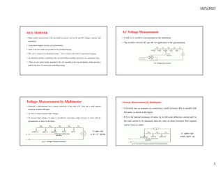
  • 1. 10/5/2022 1 MUL TIMETER • Many (multi) measurements with reasonable accuracies such as AC and DC voltages, currents, and resistances. • A permanent magnet moving coil galvanometer. • There is an iron cored coil pivoted on two jeweled bearings. • The coil is wound on an aluminum former - free to rotate in the field of a permanent magnet. • An aluminum pointer is attached to the coil and bobbin assembly and moves on a graduated scale. • There are two spiral springs attached to the coil assembly at the top and bottom, which provide a path for the flow of current and controlling torque. Voltage Measurement by Multimeter • Generally, a galvanometer has a current sensitivity of the order of 0.1 mA and a small internal resistance of about 500 ohms. • As such, it cannot measure high voltages. • To measure high voltages, its range is extended by connecting a high resistance in series with the galvanometer as shown in the figure. AC Voltage Measurement • A full-wave rectifier is incorporated in the multimeter. • The rectifier converts AC into DC for application to the galvanometer. Current Measurement by Multimeter • Converted into an ammeter by connecting a small resistance Rsh in parallel with the meter, as shown in the figure. • If G is the internal resistance of meter, Ig its full-scale deflection current and I is the total current to be measured, then the value of shunt resistance Rsh required can be found as under:
  • 2. 10/5/2022 2 Resistance Measurement by a Multimeter • In this circuit, an internal battery is connected in series with the meter through an adjustable resistance r and the fixed resistances. • The fixed resistances limit the current within the desired range, and the variable resistance r is used for zero adjustments. • The resistance to be measured (test resistance) is connected between test leads. The current flowing through the circuit depends upon the resistance of the test piece. The deflection of the needle indicates current, but the scale is calibrated in ohms to give the value of resistance directly. ELECTRODYNAMOMETER TYPE INSTRUMENTS • A transfer instrument is one that may be calibrated with a d.c. source and then used without modification to measure a.c. • This requires the transfer type instrument to have same accuracy for both d.c. and a.c., which the electrodynamometer instruments have. • Electrodynamic instruments are capable of service as transfer instruments. Indeed, their principal use as ammeters and voltmeters in laboratory and measurement work is for the transfer calibration of working instruments and as standards for calibration of other instruments as their accuracy is very high. Construction of Electrodynamometer type instrument Fixed Coil: • The field is produced by a fixed coil. • This coil is divided into two sections to give a more uniform field near the centre and to allow passage of the instrument shaft. Moving Coil: • A single element instrument has one moving coil. • The moving coil is wound either as a self-sustaining coil or else on a non- metallic former. • Light but rigid construction is used for the moving coil. • It should be noted that both fixed and moving coils are air cored. Control The controlling torque is provided by two control springs. These springs act as leads to the moving coil. Moving System The moving coil is mounted on an aluminum spindle and it carries the counter weights and truss type pointer Damping Air friction damping is employed for these instruments and is provided by a pair of aluminum vanes, attached to the spindle at the bottom. These vanes move in sector shaped chambers. Shielding The field produced by the fixed coils is somewhat weaker than in other types of instruments It is nearly 0.005 to 0.006 Wb/m - necessary to shield an electrodynamometer type instrument from the effect of stray magnetic fields.
  • 3. 10/5/2022 3 Torque Equation Total electrical input energy = change in energy stored + mechanical energy. Errors in Electrodynamometer Instruments i) Frequency error ii) Eddy current error iii) External magnetic field iv) Temperature changes Advantages i) These instruments can be used on both a.c & d.c Disadvantages (i) They have a low torque/weight ratio and hence have a low sensitivity. (ii) Low torque/weight ratio gives increased frictional losses. (iii) They are more expensive than either the PMMC or the moving iron type instruments. ELECTRODYNAMOMETER TYPE WATTMETER Moving coil: • Moving coil moves the pointer with the help of spring control. • The moving coil is air cored and is mounted on a pivoted spindle and can moves freely. • In electrodynamometer type wattmeter, moving coil works as pressure coil. Hence moving coil is connected across the voltage and thus the electric current owing through this coil is always proportional to the voltage. Fixed coil: •The fixed coil is divided into two equal parts and these are connected in series with the load, •These coils are called the electric current coils of electrodynamometer type wattmeter. Control system: i. Gravity control – Using Weight ii. Spring control, only spring controlled systems are used in these types of wattmeter. Damping system: Air friction damping is used, as eddy current damping will distort the weak operating magnetic field and thus it may leads to error. Scale: There is uniform scale is used in these types of instrument as moving coil moves linearly over a range of 40 degrees to 50 degrees on either sides.
  • 4. 10/5/2022 4 Expressions for the deflecting torque: • Let I1 and I2 be the instantaneous values of currents in pressure and electric current coils respectively. So the expression for the torque can be written as: The expression for instantaneous electric current through pressure coil can be written as If there is phase difference between voltage and electric current, then expression for instantaneous electric current through electric current coil can be written as Hence the instantaneous value of torque can be written as Errors in Electrodynamometer Type Wattmeter Pressure coil inductance: • In an ideal dynamo-meter type watt meter the current in pressure coil in phase with the applied voltage. • In the absence of inductance in pressure coil of wattmeter, it will read correctly in all power factors and frequency. • Practically Pressure coil of watt meter has an inductance and current in it will lag behind the applied voltage. • The wattmeter will read high when the load power factor is lagging ,as in that case the effect of pressure coil inductance is to reduce the phase angle between load current and pressure coil current Compensation for inductance of pressure coil. • Inductance of pressure coil can be reduced by means of capacitor connected in parallel • with a portion of multiplier (series resistance). Pressure coil capacitance. The pressure coil circuit may have capacitance in addition with inductance. This capacitance mainly due to the inter turn capacitance of the series resistance. The effect of capacitance is opposite to that due to inductance. Therefore the wattmeter will read high when the load power factor is leading. The inductance in pressure coil circuit will always more than inductance, hence the error caused by capacitance will be nullified by that due to inductance. Error due to mutual inductance. Errors may occur due to the mutual inductance between the current and pressure coils of the watt meter. These errors are quite low at power frequencies. But they increased with increase in frequencies. The effect of mutual inductance can be avoided by arranging the coil system in such a way that they have no mutual inductance. Stray Magnetic field Errors. The electrodynamometer type wattmeter has a weak operating field and therefore it is affected by stray magnetic fields it will result in serious errors. Hence these instruments should be shielded against stray magnetic field. Errors caused by vibration of moving system. The torque on the moving system varies with frequency which is twice that of voltage. If the parts of the moving system have a natural frequency which is resonance with the frequency, he moving system would vibrate with considerable amplitude. These vibrations will cause errors. This error can be reduced by design.
  • 5. 10/5/2022 5 Three Phase Power Measurement Three Phase Power Measurement Three Phase Power Measurement Three Phase Power Measurement Various methods are used measurement of three phase power in three phase circuits on the basis of number of wattmeter used. We have three methods i. Three wattmeter method. ii. Two wattmeter method. iii. Single 3-phase wattmeter method. Three wattmeter method: • Applied to three phase four wire systems, electric current coil of all the three wattmeter marked as one, two and three are connected to respective phases marked as one, two and three. • Pressure coils of all the three wattmeter are connected to common point at neutral line. • Each wattmeter will give reading as product of phase electric current and line voltage which is phase power. • The resultant sum of all the readings of wattmeter will give the total power of the circuit. Measurement of Three Phase Power by Two Wattmeter Method But, we have I1+I2+I3=0, hence putting the value of I1+I2=-I3. We get total power as V1I1+V2I2+V3I3.