
Recommended
Recommended
More Related Content
What's hot
What's hot (18)
Viewers also liked
Viewers also liked (10)
Similar to ED2 axo
Similar to ED2 axo (11)
More from tedjurca
More from tedjurca (14)
Recently uploaded
Recently uploaded (20)
ED2 axo
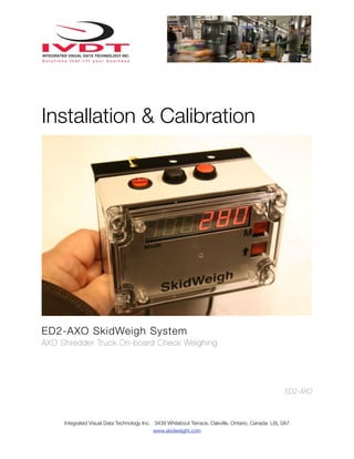
- 1. Installation & Calibration ED2-AXO SkidWeigh System AXO Shredder Truck On-board Check Weighing ED2-AXO Integrated Visual Data Technology Inc. 3439 Whilabout Terrace, Oakville, Ontario, Canada L6L 0A7 www.skidweight.com
- 2. General Installation Guide This ED2-AXO SkidWeigh system installation & calibration guide describes how to install, calibrate, test and use your onboard check weighing unit. Following the instructions in this guide will enable you to get your system operating quickly and easily. In the event that you require additional assistance, please contact customer support via e-mail to support@skidweigh.com , visit www.skidweight.co or contact us at the address or contact number below: Integrated Visual Data Technology Inc. 3439 Whilabout Terrace, Oakville, ON, Canada, L6L 0A7 Phone: 905-469-0985 Safety Always disconnect the vehicle battery while installing SkidWeigh system or any other electronic product. Make sure sure that unit, pressure transducer and any other associated cables are securely mounted and do not impede any of the vehicle’s controls. Use care when routing the components cables. Route the cables where they will be protected. Use commonly accepted install practices for after market industrial vehicle electronic devices. The installation of the SkidWeigh systems should only be performed by an acknowledged lift truck dealer technician or end user electro and hydraulic technical installer. Here are two acceptable methods of making a wire connections: * Soldering your connections (recommended) * Crimp connectors ( with the use of the proper crimping tool) Regardless of the method you choose, ensure that the connection is mechanically sound and properly insulated. Use high quality electrical tape and shrink tubing where necessary. This product is connected directly to the vehicle’s ignition switch, operating voltage from 12 to 55 V DC. Electro-Magnetic Compatibility CE conformity to EC directive 89/336 (EMC) by application of harmonized standards: Interference stability EN 61000-6-2 and EN 61326-1 interference emit EN 61000-6-3, EN 61326-1 for the pressure transducer. ED2-AXO SkidWeigh Series Our policy is one of continuous improvement and the information in this document is subject to change without notice. Check that software version displayed on LED is the one applicable for your application. Overview of components The standard ED2-AXO SkidWeigh Series check weighing system consist of two main components: * Digital indicator with wiring harness, mounting bracket and anti-vibration mount * Hydraulic pressure transducer with 3 wires cable * Installation & Calibration manual and operator usage instruction Integrated Visual Data Technology Inc. 3439 Whilabout Terrace, Oakville, Ontario, Canada L6L 0A7 www.skidweight.com
- 3. Operational principal The ED2-AXO SkidWeigh system operational principal is based on the hydraulic pressure transducer mounted in the vehicle lifting hydraulic circuit that will automatically activate the “weighing cycle / specific algorithm ” every time a container load is lifted just above the ground. Lift motor control circuit interrupt relay N.C. contacts in the ED2 digital indicator will stop movement of the lift cylinder until the load weight is shown on digital display.The increase in pressure is converted in an electronic signal at the sample rate of 16000 readings which is converted into a load weight reading. Pressure transducer installation The pressure transducer must be installed in the lifting hydraulic line between the lift control valve and lift cylinder(s). Mount a T-piece in hydraulic line. Lift motor control circuit interrupt Use two wires (Green and Blue ) from digital indicator cable to “splice” them into control circuit that controls activation of the lift motor. Both wires are connected through relay normaly cloased N.C. contacts in the SkidWeigh system. Make sure that you do not exceed maximum of 2A when connecting two wires into lift motor control circuit to interrupt lift motor operation. Pressure transducer installation precautions Before installation of the pressure transducer the hydraulic lift circuit must be pressure free. 1. Place the lifting assembly to lowest position and make the hydraulic system pressure free. 2. Make sure that that installed pressure transducer will not touch any moving parts or assembly of the vehicle while in normal operation. Pressure transducer has 1/4”-18 NPT male thread. Use thread seal to ensure tight fit. Selecting the mounting location for digital indicator Use the mounting bracket with the anti vibration mount and fasten digital indicator on the vehicle control box or any other convenient place on the truck body There are many examples of mounting locations that will depend on the vehicle model. However, additional mounting items such as a flat brackets may be needed to help secure the unit. Choose the correct location and make sure that: - Indicator is visible and within reach of the operator Integrated Visual Data Technology Inc. 3439 Whilabout Terrace, Oakville, Ontario, Canada L6L 0A7 www.skidweight.com
- 4. Compact size All of the SkidWeigh systems are compact size, housing dimension of only 120 x 80 x 55 mm. ED2-AXO system with 3 switches. - Main power switch On / Off System disable) - Black button, ADDITION - RED button, PRINT ticket and RESET Electrical Connections (Seven wires cable) All SkidWeigh systems operate from 12 to 55 V DC. - Orange Wire (+) Ignition switch On position - Brown Wire (-) Battery negative - Red Wire, connect to RED wire of the pressure transducer cable - Black Wire, connect to BLACK wire of the pressure transducer cable - White Wire, connect to WHITE wire of the pressure transducer cable BLUE and GREEN wires (Splice them into the lift motor control circuit in series with vehicle original interrupt switch or lift interrupt indicator ) Note: Splice only in lift motor control circuit or lift motor relay, max. 2A. LIFT X Transducer cable (Pressure transducer cable must be connected to the digital indicator main cable) - White Wire, signal 0 to 2,5 V - Black Wire, signal negative - Red Wire, power supply to pressure transducer + 11 V DC Integrated Visual Data Technology Inc. 3439 Whilabout Terrace, Oakville, Ontario, Canada L6L 0A7 www.skidweight.com MOTOR
- 5. Electrical power short circuit protection - All of the SkidWeigh systems are internally short circuit protected with resettable fuse. There is no need to install external inline fuse in orange wire connected to the ignition switch. - Automotive 60 V load dump protection - Reversal power supply protection -Note: Any external devices connected to the SkidWeigh system, such as non standard onboard printer might require external fuse. “Quick test to determine if electrical connections are done right” Note: SkidWeigh weighing calibration function is not done yet at this stage. This procedure is only to test if electrical connections of the system installation into the vehicle is done properly! After you have connected electrical power and pressure transducer cable you can “quickly” check the system operation. - Turn on the power switch ( Ignition sw.) - Activate main power switch located on top of the housing - Lower the lifting assembly to the ground - Digital LED display will be activated, showing software version - Number 8 will be shown on LED display above the Mode sign. - Lift some container load just above the ground. Mode 8 will go off, lift motor will stop and some load weight will be shown on LED display. When LED display shows the load weight the contact in SkidWeigh unit will close and lift motor circuit will be operational. If the above test is valid than the system electrical connections are done right. The next procedure will be to calibrate the SkidWeigh weighing function and perhaps set the right time and date if current value is wrong. Weighing function calibration procedure The ED2-AXO SkidWeigh calibration is automatic and is done by lifting empty and loaded forks just above the ground. MAKE SURE THAT YOU HAVE A KNOWN LOAD WEIGHT AND KEEP IT NEARBY TO COMPLETE THE CALIBRATION. For the best results use at least minimum calibration load test weight of 30 to 50% of maximum lifting capacity of the lift truck. Use customer floor scale or find a known skid load weight within the operational facility. Important: If you want the system to show load weight in pounds, use the known load weight in pounds and enter that value accordingly. The same would apply if you want the system to show load weight in kilograms. Use the known load weight in kilograms and enter that value into the system accordingly. Integrated Visual Data Technology Inc. 3439 Whilabout Terrace, Oakville, Ontario, Canada L6L 0A7 www.skidweight.com
- 6. Calibration starting point Lower the empty lifting assembly to the ground. There should be no hydraulic pressure in lift hydraulic circuit. - Turn ignition switch to on position . IF the LED display does not show any numbers, turn on the main power switch located on top of the housing. - LED display will show software version on the right side and number 8 will be shown in Mode window. Calibration of empty lifting assembly lifted just above the ground - With lowered empty lifting assembly on the ground the Mode 8 will be shown on LED display. To initiate calibration press the “M” key (use a paper clip) and hold it down for approx. 5 seconds. After 5 seconds the Mode 8 digit will change to Mode 0. System is ready for automatic zeroing of the scale function Integrated Visual Data Technology Inc. 3439 Whilabout Terrace, Oakville, Ontario, Canada L6L 0A7 www.skidweight.com
- 7. Lift the empty lifting assembly just above the ground. Wait few seconds, lift motor will stop, LED display will go blank and will show “0” value in furthest right digit display. The ED2-AXO automatic zero weight function is finished Calibration of loaded forks lifted just above the ground At this point drive your vehicle into the contaner load with your known load calibration weight. - Lower the loaded lifting assembly to the ground. (In our example the known calibration load weight is 4000 pounds) - In AXO application known load would be in the area of 200 to 400 pounds) Integrated Visual Data Technology Inc. 3439 Whilabout Terrace, Oakville, Ontario, Canada L6L 0A7 www.skidweight.com
- 8. - Start entering a known load weight into digital indicator by using arrow up button (increments from 0 to 9) with wrap around function. Start with least significant digit of your known load weight. - Use the “M” button to increment to next digit on the LED display First least Second least Third least Forth least significant digit “0” significant digit “0” significant digit “0” Must enter “0” significant digit “4” - Repeat this procedure until the Mode digit display is showing number 4. Caution: Since in our example of 4000 pounds known load weight value has only four digits make sure that the 5th digit has “0” value entered into the calibration system. - With loaded forks still on the ground press “M” button to advance to Mode 6. - Lift loaded forks just above the ground. Within few seconds display will show the value of the known load weight. The ED2-AXO system weighing calibration function is finished If you lower the loaded forks to the ground the Mode 8 digit will be shown on LED display. The Mode 8 shown on LED display is always your starting point to initiate a weighing cycle . System is ready to be Integrated Visual Data Technology Inc. 3439 Whilabout Terrace, Oakville, Ontario, Canada L6L 0A7 www.skidweight.com
- 9. ED2-AXO SkidWeigh, Lift Truck Operator Proper Weighing Procedure Note1: This load weight will be shown on LED display until next time the forks are lowered to ground. Note 2: When vehicle in motion the LED might show some random load weight. This is due to the hydraulic spikes and this does not represents any actual load weight value. To initiate the “weighing cycle” you must lower the loaded forks to the ground. Once the Mode 8 is shown, lift loaded forks just above the ground to obtain a load weight. Note 3: During the normal operation if you do not want to use the weighing function, turn off the main power switch located on the top of the housing. LED display will not show anything and you can operate your electric pallet truck without weighing cycle and without lift motor being stopped. Weighing Bins - When power to the vehicle is turned on the LED display should show Software version. (Example: Software version 30075). If nothing is shown on LED display, turn on the main power switch to the system which is located on top of the digital indicator. - Insert the liftong assembly into the container product to be weighed. - Lifting assembly must be at lowest lifting point - LED display must show number 8 to initiate the “weighing cycle”. - Activate lift control valve and start lifting load forks. - Lift motor will stop until load weight is shown on LED display - LED display will go blank for the moment and within few seconds load weight will be displayed. - Lift motor will be operational once the load weight is shown on the LED display. Load Weight Total + Print Tickets - ED2-AXO SkidWeigh Series with load weight function will have additional two buttons on top of the housing - Black button to be pressed to accumulate loads (LED display must show a load weight in order to add load weights) - Red button to be pressed to reset current or accumulative total load weight . Print Tickets - ED2-AXO with onboard printer - Red button to be pressed to print current single load weight ticket and / or accumulative total load weight and reset Integrated Visual Data Technology Inc. 3439 Whilabout Terrace, Oakville, Ontario, Canada L6L 0A7 www.skidweight.com