SlideShare a Scribd company logo
1 of 6
Download to read offline
Seismic design and assessment of
                  Seismic design and assessment of
                    Masonry Structures
                    Masonry Structures

                   Lesson 14, continued
                                 October 2004


                                  Masonry Structures, lesson 14 part 2 slide 1


Example of assessment with rigid-body mechanism analysis

 Out-of-plane failure of gable walls


                                                                         1.5 m


                                                                                  6.0 m


                                            9.0 m


                                                                          6.0 m


                                  Masonry Structures, lesson 14 part 2 slide 2
1.50 cm
                                                                  o

                           1.5 m


                                    6.0 m


                                                                                     6.00 m
                                                            0.40 m


9.0 m


                            6.0 m


                                       Masonry Structures, lesson 14 part 2 slide 3


                                                       P
                 1.50 cm


                                                            αP'       ∆x1

           o
                                                                            1.50 m


                                                                  ∆x0
                                                           αW
                 6.00 m


        0.40 m
                                                       W
                                               .50 m


                                                           ∆y0    O

                                                       .40 m


                                       Masonry Structures, lesson 14 part 2 slide 4
P
                                                                   weight/m2 of roof (including truss structures):
                          αP'       ∆x1
                                                                   1.4 kN/ m2
                                                                   weight of masonry: 20 kN/m3
                                                                   assume each gable wall carries 1/3 of vertical
                                                                   weight carried by top ridge beam, P = 26 kN
                                                                   P’=1/2 of weight = 1.5 P = 39 kN
                                                   1.50 m


                                ∆x0                                centre of mass of gable wall: 1/3 of height
                        αW
                    W                                              assume P applied at centreline of wall
        .50 m


                                                                 Direct moment equilibrium at incipient rocking:

                        ∆y0         O                             α 0 (1.5 ⋅ P'+0.5 ⋅W ) − 0.2 ⋅ P − 0.2 ⋅W = 0
                                                                                      0.2 ⋅ P + 0.2 ⋅W
                     .40 m                                                   α0 =                      = 0.162
                                                                                      1.5 ⋅ P'+0.5 ⋅W
                                                                             Masonry Structures, lesson 14 part 2 slide 5


                P                                           or, through application of PVW:
                     αP'        ∆x1
                                                               α 0 P '⋅∆ x1 + α 0W ⋅ ∆ x 0 − P ⋅ ∆ y 0 − W ⋅ ∆ y 0 = 0

                                                                 ∆ x 0 = θ ⋅ 0.5;      ∆ x1 = θ ⋅1.5;   ∆ y 0 = θ ⋅ 0.2

                                                                 α 0 P'⋅1.5θ + α 0W ⋅ 0.5θ − P ⋅ 0.2θ − W ⋅ 0.2θ = 0
                                          1.50 m


                                                                                  0.2 ⋅ P + 0.2 ⋅ W
                    αW
                              ∆x0                                       α0 =                        = 0.162
                                                                                  1.5 ⋅ P'+0.5 ⋅ W
                W
                                                             Evaluation of effective mass M*:
.50 m


                                θ
                                                             use ∆x1 as control displacement, ∆x0 = ∆x1 /3
                                                                                  2
                                                                  ⎛ n +m      ⎞
                                                                  ⎜ ∑ Piδ x,i ⎟
                    ∆y0       O
                                                            M * = ⎝ i =n1+ m  ⎠ =    (P'⋅1 + W ⋅ 0.333)2 = 6.162
                .40 m                                               g ∑ Piδ x,i
                                                                             2                (
                                                                                  9.81 ⋅ P'⋅12 + W ⋅ 0.3332          )
                                                                      i =1

                                                                             Masonry Structures, lesson 14 part 2 slide 6
P                                           effective mass ratio e* :
             αP'       ∆x1
                                                                 n+m
                                                                             9.81⋅ 6.162
                                                 e* = gM * / ∑ Pi =                      = 0.806
                                                                 i =1          W + P'

                                                Evaluation of effective static acceleration threshold a0*:
                                                             n+ m
                                                          α 0 ∑ Pi
                             1.50 m


            αW
                      ∆x0                                                   α0 g         0.162 ⋅ 9.81
                                                   a0 =
                                                    *        i =1
                                                                *
                                                                        =        *
                                                                                     =                = 1.972 m/s 2
        W
                                                            M                e              0.806
.50 m


                       θ
                                                 “Linear” static safety check (ultimate limit state):

            ∆y0       O                                  a gS ⎛       Z⎞
                                                  a* ≥
                                                   0          ⎜1 + 1.5 ⎟                 with q = 2.0
                                                          q ⎝         H⎠
        .40 m


                                                           Masonry Structures, lesson 14 part 2 slide 7
                                      1.50 cm


                                                   “Linear” static safety check (ultimate limit state):

                  o                                        a gS ⎛       Z⎞
                                                    a* ≥
                                                     0          ⎜1 + 1.5 ⎟                 with q = 2.0
                                                            q ⎝         H⎠

                                                       Z                     where Z= 7.02 m is height of
                                                         = 0.78
                                                       H                     centroid of weights P’ and W with
                                      6.00 m


            0.40 m
                                                                             respect to ground and Z = 7.5 m

                                                                 ag S
                                                          a0 ≥
                                                           *
                                                                        (1 + 1.5 ⋅ 0.936) = 1.202ag S
                                                                 2.0

                                                    mechanism is verified if agS ≤ a0*/1.202 = 1.641 m/s2
                                                    = 0.167g


                                                           Masonry Structures, lesson 14 part 2 slide 8
P                               Noninear static safety check (ultimate limit state)
             αP'    ∆x1
                                        Evaluate static α-∆x1 (α-dk ) relationship for
                                        finite displacement. All forces are proportional
                                        to weigths, therefore α-dk relationship is
                                        linear:
                                                  α = α 0 (1 − d k / d k ,0 )
                          1.50 m


                   ∆x0
            αW
                                         Evaluate displacement dk,0 at zero horizontal
        W
                                         force (i.e. zero restoring moment):
.50 m


                    θ
                                                  W ⋅ (0.2 − ∆ x 0 ) − P ⋅ (0.2 − ∆ x1 ) = 0
            ∆y0    O                              W ⋅ (0.2 − ∆ x1 / 3) − P ⋅ (0.2 − ∆ x1 ) = 0
                                                                       W ⋅ 0.2 + P ⋅ 0.2
        .40 m                                    ∆ x1, 0 = d k , 0 =                     = 0.326 m
                                                                         W /3+ P

                                              Masonry Structures, lesson 14 part 2 slide 9


        P
             αP'    ∆x1
                                        Evaluate effective displacement of equivalent
                                        sdof system:
                                               n+m
                                               ∑ Pi δ x,i                 P '⋅1 + W ⋅ 0.333
                                               i =1
                                   d = dk
                                    *
                                                      n+m
                                                                = dk                        = 0.68 ⋅ d k
                                                                              1⋅ ( P'+W )
                                              δ x,k   ∑ Pi
                          1.50 m


                   ∆x0                                i =1
            αW
        W                                    d * = 0.68 ⋅ d k,0 = 0.222 m
.50 m


                                               0
                    θ
                                             d * = 0.4 ⋅ d * = 0.089 m
                                               u           0
            ∆y0    O
                                              d * = 0.4 ⋅ d * = 0.035 m
                                                s           u

        .40 m


                                              Masonry Structures, lesson 14 part 2 slide 10
d * = 0.68 ⋅ d k,0 = 0.222 m
                                                                 0

a*                                                             d * = 0.4 ⋅ d * = 0.089 m
                                                                 u           0

                                         d s*                  d * = 0.4 ⋅ d * = 0.035 m
a0   *                      Ts* = 2π       *
                                                                 s           u
                                         as
a s*                                                                Ts* = 0.92 sec


           (2π/T s*)2


               ds*=0.4du*      du*=0.4d0*                               d0*          d*


                                                Masonry Structures, lesson 14 part 2 slide 11


Assume fundamental period of building had been determined previously as
T1=0.2 sec
Then Ts*=0.92 >1.5 T1=0.3 sec
therefore, assuming, e.g. agS = 0.2g = 1.962 m/s2 , the effective displacement
demand is:

                                   T1Ts* ⎛          Z⎞
         ∆ (Ts* ) = a g S ⋅1.5 ⋅       2 ⎜
                                           1.9 + 2.4 ⎟ = 0.071 m < 0.089 m = d *
                                   4π ⎝
                                                                               u
                                                    H⎠


                                                Masonry Structures, lesson 14 part 2 slide 12

More Related Content

More from Teja Ande

Approximate Methods
Approximate MethodsApproximate Methods
Approximate MethodsTeja Ande
 
Lesson9 2nd Part
Lesson9 2nd PartLesson9 2nd Part
Lesson9 2nd PartTeja Ande
 
Lecture 13 Building Populations
Lecture 13 Building PopulationsLecture 13 Building Populations
Lecture 13 Building PopulationsTeja Ande
 
Lecture 11 Performance Based Evaluation
Lecture 11 Performance Based EvaluationLecture 11 Performance Based Evaluation
Lecture 11 Performance Based EvaluationTeja Ande
 
Lecture 6 7 Rm Shear Walls
Lecture 6 7 Rm Shear WallsLecture 6 7 Rm Shear Walls
Lecture 6 7 Rm Shear WallsTeja Ande
 
Lecture 10 Urm Out Of Plane Walls Part 2
Lecture 10 Urm Out Of Plane Walls Part 2Lecture 10 Urm Out Of Plane Walls Part 2
Lecture 10 Urm Out Of Plane Walls Part 2Teja Ande
 
Lecture 6 7 Rm Shear Walls
Lecture 6 7 Rm Shear WallsLecture 6 7 Rm Shear Walls
Lecture 6 7 Rm Shear WallsTeja Ande
 
Lecture 4 5 Urm Shear Walls
Lecture 4 5 Urm Shear WallsLecture 4 5 Urm Shear Walls
Lecture 4 5 Urm Shear WallsTeja Ande
 
Lecture 2 3 Compression, Condition Assess
Lecture 2 3 Compression, Condition AssessLecture 2 3 Compression, Condition Assess
Lecture 2 3 Compression, Condition AssessTeja Ande
 
Lecture 4 5 Urm Shear Walls
Lecture 4 5 Urm Shear WallsLecture 4 5 Urm Shear Walls
Lecture 4 5 Urm Shear WallsTeja Ande
 
Lecture 2 3 Compression, Condition Assess
Lecture 2 3 Compression, Condition AssessLecture 2 3 Compression, Condition Assess
Lecture 2 3 Compression, Condition AssessTeja Ande
 
Masonry Code Of Practice Amp
Masonry Code Of Practice   AmpMasonry Code Of Practice   Amp
Masonry Code Of Practice AmpTeja Ande
 
Masonry Retrofit
Masonry RetrofitMasonry Retrofit
Masonry RetrofitTeja Ande
 
Chapter11 Masonry
Chapter11 MasonryChapter11 Masonry
Chapter11 MasonryTeja Ande
 
Chapter12 Masonry
Chapter12 MasonryChapter12 Masonry
Chapter12 MasonryTeja Ande
 

More from Teja Ande (20)

Approximate Methods
Approximate MethodsApproximate Methods
Approximate Methods
 
Lesson14
Lesson14Lesson14
Lesson14
 
Lesson10
Lesson10Lesson10
Lesson10
 
Lesson9 2nd Part
Lesson9 2nd PartLesson9 2nd Part
Lesson9 2nd Part
 
Lesson8
Lesson8Lesson8
Lesson8
 
Lesson9
Lesson9Lesson9
Lesson9
 
Lecture 13 Building Populations
Lecture 13 Building PopulationsLecture 13 Building Populations
Lecture 13 Building Populations
 
Lesson1
Lesson1Lesson1
Lesson1
 
Lecture 11 Performance Based Evaluation
Lecture 11 Performance Based EvaluationLecture 11 Performance Based Evaluation
Lecture 11 Performance Based Evaluation
 
Lecture 6 7 Rm Shear Walls
Lecture 6 7 Rm Shear WallsLecture 6 7 Rm Shear Walls
Lecture 6 7 Rm Shear Walls
 
Lecture 10 Urm Out Of Plane Walls Part 2
Lecture 10 Urm Out Of Plane Walls Part 2Lecture 10 Urm Out Of Plane Walls Part 2
Lecture 10 Urm Out Of Plane Walls Part 2
 
Lecture 6 7 Rm Shear Walls
Lecture 6 7 Rm Shear WallsLecture 6 7 Rm Shear Walls
Lecture 6 7 Rm Shear Walls
 
Lecture 4 5 Urm Shear Walls
Lecture 4 5 Urm Shear WallsLecture 4 5 Urm Shear Walls
Lecture 4 5 Urm Shear Walls
 
Lecture 2 3 Compression, Condition Assess
Lecture 2 3 Compression, Condition AssessLecture 2 3 Compression, Condition Assess
Lecture 2 3 Compression, Condition Assess
 
Lecture 4 5 Urm Shear Walls
Lecture 4 5 Urm Shear WallsLecture 4 5 Urm Shear Walls
Lecture 4 5 Urm Shear Walls
 
Lecture 2 3 Compression, Condition Assess
Lecture 2 3 Compression, Condition AssessLecture 2 3 Compression, Condition Assess
Lecture 2 3 Compression, Condition Assess
 
Masonry Code Of Practice Amp
Masonry Code Of Practice   AmpMasonry Code Of Practice   Amp
Masonry Code Of Practice Amp
 
Masonry Retrofit
Masonry RetrofitMasonry Retrofit
Masonry Retrofit
 
Chapter11 Masonry
Chapter11 MasonryChapter11 Masonry
Chapter11 Masonry
 
Chapter12 Masonry
Chapter12 MasonryChapter12 Masonry
Chapter12 Masonry
 

Lesson14 Exmpl

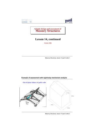
  • 1. Seismic design and assessment of Seismic design and assessment of Masonry Structures Masonry Structures Lesson 14, continued October 2004 Masonry Structures, lesson 14 part 2 slide 1 Example of assessment with rigid-body mechanism analysis Out-of-plane failure of gable walls 1.5 m 6.0 m 9.0 m 6.0 m Masonry Structures, lesson 14 part 2 slide 2
  • 2. 1.50 cm o 1.5 m 6.0 m 6.00 m 0.40 m 9.0 m 6.0 m Masonry Structures, lesson 14 part 2 slide 3 P 1.50 cm αP' ∆x1 o 1.50 m ∆x0 αW 6.00 m 0.40 m W .50 m ∆y0 O .40 m Masonry Structures, lesson 14 part 2 slide 4
  • 3. P weight/m2 of roof (including truss structures): αP' ∆x1 1.4 kN/ m2 weight of masonry: 20 kN/m3 assume each gable wall carries 1/3 of vertical weight carried by top ridge beam, P = 26 kN P’=1/2 of weight = 1.5 P = 39 kN 1.50 m ∆x0 centre of mass of gable wall: 1/3 of height αW W assume P applied at centreline of wall .50 m Direct moment equilibrium at incipient rocking: ∆y0 O α 0 (1.5 ⋅ P'+0.5 ⋅W ) − 0.2 ⋅ P − 0.2 ⋅W = 0 0.2 ⋅ P + 0.2 ⋅W .40 m α0 = = 0.162 1.5 ⋅ P'+0.5 ⋅W Masonry Structures, lesson 14 part 2 slide 5 P or, through application of PVW: αP' ∆x1 α 0 P '⋅∆ x1 + α 0W ⋅ ∆ x 0 − P ⋅ ∆ y 0 − W ⋅ ∆ y 0 = 0 ∆ x 0 = θ ⋅ 0.5; ∆ x1 = θ ⋅1.5; ∆ y 0 = θ ⋅ 0.2 α 0 P'⋅1.5θ + α 0W ⋅ 0.5θ − P ⋅ 0.2θ − W ⋅ 0.2θ = 0 1.50 m 0.2 ⋅ P + 0.2 ⋅ W αW ∆x0 α0 = = 0.162 1.5 ⋅ P'+0.5 ⋅ W W Evaluation of effective mass M*: .50 m θ use ∆x1 as control displacement, ∆x0 = ∆x1 /3 2 ⎛ n +m ⎞ ⎜ ∑ Piδ x,i ⎟ ∆y0 O M * = ⎝ i =n1+ m ⎠ = (P'⋅1 + W ⋅ 0.333)2 = 6.162 .40 m g ∑ Piδ x,i 2 ( 9.81 ⋅ P'⋅12 + W ⋅ 0.3332 ) i =1 Masonry Structures, lesson 14 part 2 slide 6
  • 4. P effective mass ratio e* : αP' ∆x1 n+m 9.81⋅ 6.162 e* = gM * / ∑ Pi = = 0.806 i =1 W + P' Evaluation of effective static acceleration threshold a0*: n+ m α 0 ∑ Pi 1.50 m αW ∆x0 α0 g 0.162 ⋅ 9.81 a0 = * i =1 * = * = = 1.972 m/s 2 W M e 0.806 .50 m θ “Linear” static safety check (ultimate limit state): ∆y0 O a gS ⎛ Z⎞ a* ≥ 0 ⎜1 + 1.5 ⎟ with q = 2.0 q ⎝ H⎠ .40 m Masonry Structures, lesson 14 part 2 slide 7 1.50 cm “Linear” static safety check (ultimate limit state): o a gS ⎛ Z⎞ a* ≥ 0 ⎜1 + 1.5 ⎟ with q = 2.0 q ⎝ H⎠ Z where Z= 7.02 m is height of = 0.78 H centroid of weights P’ and W with 6.00 m 0.40 m respect to ground and Z = 7.5 m ag S a0 ≥ * (1 + 1.5 ⋅ 0.936) = 1.202ag S 2.0 mechanism is verified if agS ≤ a0*/1.202 = 1.641 m/s2 = 0.167g Masonry Structures, lesson 14 part 2 slide 8
  • 5. P Noninear static safety check (ultimate limit state) αP' ∆x1 Evaluate static α-∆x1 (α-dk ) relationship for finite displacement. All forces are proportional to weigths, therefore α-dk relationship is linear: α = α 0 (1 − d k / d k ,0 ) 1.50 m ∆x0 αW Evaluate displacement dk,0 at zero horizontal W force (i.e. zero restoring moment): .50 m θ W ⋅ (0.2 − ∆ x 0 ) − P ⋅ (0.2 − ∆ x1 ) = 0 ∆y0 O W ⋅ (0.2 − ∆ x1 / 3) − P ⋅ (0.2 − ∆ x1 ) = 0 W ⋅ 0.2 + P ⋅ 0.2 .40 m ∆ x1, 0 = d k , 0 = = 0.326 m W /3+ P Masonry Structures, lesson 14 part 2 slide 9 P αP' ∆x1 Evaluate effective displacement of equivalent sdof system: n+m ∑ Pi δ x,i P '⋅1 + W ⋅ 0.333 i =1 d = dk * n+m = dk = 0.68 ⋅ d k 1⋅ ( P'+W ) δ x,k ∑ Pi 1.50 m ∆x0 i =1 αW W d * = 0.68 ⋅ d k,0 = 0.222 m .50 m 0 θ d * = 0.4 ⋅ d * = 0.089 m u 0 ∆y0 O d * = 0.4 ⋅ d * = 0.035 m s u .40 m Masonry Structures, lesson 14 part 2 slide 10
  • 6. d * = 0.68 ⋅ d k,0 = 0.222 m 0 a* d * = 0.4 ⋅ d * = 0.089 m u 0 d s* d * = 0.4 ⋅ d * = 0.035 m a0 * Ts* = 2π * s u as a s* Ts* = 0.92 sec (2π/T s*)2 ds*=0.4du* du*=0.4d0* d0* d* Masonry Structures, lesson 14 part 2 slide 11 Assume fundamental period of building had been determined previously as T1=0.2 sec Then Ts*=0.92 >1.5 T1=0.3 sec therefore, assuming, e.g. agS = 0.2g = 1.962 m/s2 , the effective displacement demand is: T1Ts* ⎛ Z⎞ ∆ (Ts* ) = a g S ⋅1.5 ⋅ 2 ⎜ 1.9 + 2.4 ⎟ = 0.071 m < 0.089 m = d * 4π ⎝ u H⎠ Masonry Structures, lesson 14 part 2 slide 12