
Recomendados
Recomendados
Más contenido relacionado
La actualidad más candente
La actualidad más candente (19)
Destacado
Destacado (14)
Similar a Highly stable pt–ru nanoparticles supported on three dimensional cubic ordered mesoporous carbon (pt ru cmk-8) as promising electrocatalysts for methanol oxidation
Similar a Highly stable pt–ru nanoparticles supported on three dimensional cubic ordered mesoporous carbon (pt ru cmk-8) as promising electrocatalysts for methanol oxidation (20)
Más de tshankar20134
Más de tshankar20134 (9)
Último
Último (20)
Highly stable pt–ru nanoparticles supported on three dimensional cubic ordered mesoporous carbon (pt ru cmk-8) as promising electrocatalysts for methanol oxidation
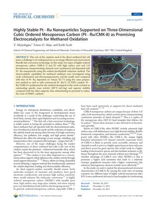
- 1. ARTICLE pubs.acs.org/JPCC Highly Stable PtÀRu Nanoparticles Supported on Three-Dimensional Cubic Ordered Mesoporous Carbon (PtÀRu/CMK-8) as Promising Electrocatalysts for Methanol Oxidation T. Maiyalagan,* Taiwo O. Alaje, and Keith Scott School of Chemical Engineering and Advanced Materials, University of Newcastle Upontyne, NE1 7RU, United Kingdom ABSTRACT: The cost of the catalysts used in the direct methanol fuel cell poses a challenge to its widespread use as an energy efficient and environment friendly fuel conversion technology. In this study, two types of highly ordered mesoporous carbon CMK-8 (I and II) with high surface area and 3-D bicontinuous interpenetrating channels were synthesized and deposited with PtÀRu nanoparticles using the sodium borohydride reduction method. The electrocatalytic capabilities for methanol oxidation were investigated using cyclic voltammetry and chronoamperometry, and the results were compared with that of PtÀRu deposited on Vulcan XC-72 using the same preparation method as well as with commercial PtÀRu/C (E-TEK) catalyst. PtÀ Ru/CMK-8-I synthesized by the method developed in this work revealed an outstanding specific mass activity (487.9 mA/mg) and superior stability compared with the other supports, thus substantiating its potential to reduce the costs of DMFC catalysts. 1. INTRODUCTION Energy, its widespread distribution, availability, and affordability has come to the foreground in developmental issues worldwide as a result of the challenges confronting the use of fossil fuels, namely, their rapid depletion and increasing environmental pollution.1À3 The fuel cell, a fuel conversion technology, is widely touted as having the potential to address these.4,5 The direct methanol fuel cell operated with the electrochemical oxidation of methanol as fuel at the anode and the reduction of oxygen at the cathode stands out among others because of its high conversion efficiency, low pollution, low weight, and high power density.6 Methanol also offers the advantage of easy storage, refuelling, and transportation when compared with hydrogenÀoxygen fuel cell.7,8 However, one of the major challenges facing the market competitiveness of direct methanol fuel cells is the cost of the catalyst, mainly the platinumÀruthenium bimetallic alloy, which has been discovered to be the most appropriate among other options.9À13 This catalyst is very often dispersed on a conventional carbon support, which influences the catalytic activity through metal support interaction.14À16 Hence, efforts are being channelled toward obtaining a support material that simultaneously optimizes the catalyst dispersion, loading, and electrocatalytic efficiency. An ideal support-catalyst assembly should ensure facile molecular transport of reactants and products, have good electronic conductivity, and possess high surface reactivity; these would enhance the molecular conversion.17 A highly ordered mesoporous carbon (HOMC) with tunable pore sizes, high surface area, large pore volume, and more narrow pore size distribution lends itself to the foregoing merits.18À21 In general, ordered mesoporous carbons, especially CMK-3, r 2011 American Chemical Society have been used extensively as supports for direct methanol fuel cell catalysts.22À29 CMK-8 mesoporous carbons are unique because of their 3-D cubic Ia3d mesostructure, which consists of two interpenetrating continuous networks of chiral channels.30 This is a replica of the mesoporous silica (KIT-6) hard template that follows the G-surface.31 Hence their structure is also referred to as bicontinuous gyroidal. Merits of CMK-8 like other HOMC include extremely high surface area, well-defined pore size, high thermal stability, flexible framework composition, and intrinsic conductivity.30,32,33 Compared with other HOMCs like CMK-3, the unique highly branched intertwined 3-D channel network (nanoscale level) of CMK-8 is likely to provide more accessible entrances and channels as well as serve as a highly opened porous host with easy and direct access for guest species, this would result in a higher loading of electroactive species and also facilitate inclusion or diffusion throughout the pore channels without pore blockage.34,35 Another advantage of CMK-8 over other HOMCs is that it possesses a higher Ia3d symmetry that leads to a relatively isotropic graphitized structure with a higher conductivity; this enhances heterogeneous electron transfer more effectively.36 In this study, we seek to exploit the aforementioned structural characteristics of CMK-8. By varying the mole ratio of starting reactants, two different types of highly ordered mesoporous silica KIT-6 were synthesized and used as hard template for synthesizing Received: October 26, 2011 Revised: December 11, 2011 Published: December 16, 2011 2630 dx.doi.org/10.1021/jp210266n | J. Phys. Chem. C 2012, 116, 2630–2638
- 2. The Journal of Physical Chemistry C ARTICLE Table 1. Pore Characteristics of the Mesoporous and Vulcan XC 72R Carbons BET surface total pore pore area (m2/g) volume (cm3/g) size (nm) carbon Vulcan XC 72 Ra mesoporous carbon CMK-8-I 0.67 1.26 4.9 mesoporous carbon CMK-8-II a 235 1060 1149 1.48 3.2 From ref 32. both commercial (E-TEK) and in-house PtÀRu/Vulcan XC72R revealed the potential of CMK-8 as an excellent support material for PtÀRu catalysts when used in methanol oxidation. To the best of our knowledge, this is the first application of CMK-8 HOMC in the development of catalysts for use in direct methanol fuel cells. 2. EXPERIMENTAL SECTION 2.1. Synthesis of Highly Ordered Mesoporous Silica and Carbon. The mesoporous silica was synthesized as follows.35 Figure 1. (a) Low-angle XRD patterns of CMK-8 and (b) N2 adsorptionÀ desorption isotherms of CMK-8-I and (c) CMK-8-II samples. (The inset shows their BJH pore size distributions.) two types of CMK-8 carbons (I and II) with different pore sizes; PtÀRu was deposited on the CMK-8 via the sodium borohydride reduction method. The CMK-8 HOMCs were characterized by means of N2-physisorption, X-ray diffraction (XRD), and transmission electron microscopy (TEM). The electrochemical activity and stability of the catalysts were explored using cyclic voltammetry and chronoamperometry. The results when compared with that of Typically, 6 g of triblock copolymer, EO20PO70EO20 (Pluronic P123, Sigma Aldrich) was dissolved in 217 g of deionized water and 11.628 g of 37 wt % conc. HCl (Sigma Aldrich) solution with stirring at 35 °C. After complete dissolution, 6 g of butanol was added at once with vigorous stirring. After 1 h of stirring, 12.9 g of tetraethylorthosilicate (TEOS, 98 wt %, Sigma Aldrich) was added at once to the homogeneous clear solution while still stirring. The mixture was left under vigorous and constant stirring for 24 h at 35 °C. Afterward, the mixture was placed in an oven at 100 °C and left for 24 h under static conditions (in a closed polypropylene bottle). The solid product obtained after hydrothermal treatment was filtered while hot and dried at 100 °C without washing. To complete the synthesis, the template was removed by extraction in an ethanol-HCl mixture; this was done by stirring the filtrate for 1 to 2 h in a mixture of 300À400 mL of ethanol with 20À30 mL of 37% conc. HCl, followed by calcination in air at 550 °C for 6 h. KIT-6 I and II were obtained by varying the mole ratio of reactants. The mesoporous carbon was prepared using a slight modification of a reported procedure.30 Typically, 1.25 g of sucrose (Sigma Aldrich) and 0.14 g of H2SO4 (97 to 98 wt %, Sigma Aldrich) were added to 5 g of deionized water. This was mixed with 1 g of KIT-6 mesoporous silica. The mixture was dried in an oven at a temperature of 100 °C for 6 h; the temperature was increased to 160 °C and maintained for another 6 h. To the partially decomposed sucrose was added a sucrose solution prepared with 0.75 g sucrose and 0.08 g H2SO4 in 5 g of water. The drying procedure was repeated by heating to 100 °C and holding for 6h, then to 160 °C and holding for another 6h. The carbonÀsilica composite was pyrolyzed in flowing nitrogen at a temperature of 900 °C (N2 flow: 50 mL/min; heating rate 2 °C/min) for 4 h. The carbon was recovered by dissolving the silica template in 1 M ethanolic sodium hydroxide (50% waterÀ50% ethanol v/v), filtering, and washing with ethanol. Finally, the resultant carbon was dried at 100 °C for 12 h. CMK-I and II were obtained by using KIT-6 I and II as hard templates, respectively. 2.2. Preparation of the PtÀRu/CMK-8 Electrocatalyst. PtÀRu electrocatalysts were synthesized and deposited on carbon supports by using a wet chemical reduction method. In this work, carbon-supported PtÀRu nanoparticle electrocatalyst 2631 dx.doi.org/10.1021/jp210266n |J. Phys. Chem. C 2012, 116, 2630–2638
- 3. The Journal of Physical Chemistry C ARTICLE Table 2. Structural Parameters and Chemical Composition for Various Electrocatalysts elemental composition S. no. electrocatalysts particle size XRD (nm) particle size TEM (nm) metal loading (%) Pt:Ru (at %) 1 PtÀRu/XC-72 4.64 4.0 19.28 Pt56 Ru44 2 PtÀRu/C (E-TEK) 1.91 2.6 23.2 Pt53 Ru47 3 PtÀRu/CMK-8-I 5.60 6.5 19.54 Pt57 Ru43 4 PtÀRu/CMK-8-II 3.82 5.0 19.38 Pt55 Ru45 Figure 2. XRD Pattern of (a) PtÀRu/CMK-8-I, (b) PtÀRu/CMK-8II, (c) PtÀRu/XC-72 (prepared), and (d) PtÀRu/C (E-TEK) catalyst. with atomic ratio Pt/Ru (1:1) and 20 wt % of metal loading (PtÀRu) on carbon was prepared according to the following procedure. Typically, the mesoporous carbon (40 mg) was ultrasonically dispersed in a mixture of ultrapure water and isopropyl alcohol (with a volume ratio of 1:1) for 20 min, after which a desired amount of 0.01 M H2PtCl6 (3.4 mL) (Acros) and 0.01 M RuCl3 (4.4 mL) (Aldrich) was added. The mixture was stirred for 30 min. The pH value of the ink was adjusted by adding a drop NaOH solution; then, its temperature increased to 80 °C. We added 25 mL of 0.2 mol LÀ1 solution of sodium borohydride to the ink drop by drop, and the bath was stirred for 1 h. (6.1 mg of sodium borohydride dissolved in 5 mL of deionized water was added to the ink. and the mixture was stirred for 1 h.) The mixture was cooled, dried, and washed repeatedly with ultrapure water (18.2 M 3 Ω cm) to remove excess chlorides. The catalyst powder was dried in an oven and stored. All chemicals used were of analytical grade. The catalyst was denoted as PtÀRu/CMK-8. 2.3. Characterization. Nitrogen sorption characterization of the materials was conducted on a Micromeritics ASAP2010 surface area and pore size analyzer at 77.35 K. Powder XRD was recorded on a PAN analytical X’Pert Pro MPD diffractometer using Cu Kα radiation. Morphology and microstructure of the as-obtained samples were examined using a Tecnai G2 F20X-Twin MAT high-resolution TEM, operating at an accelerating voltage of 200 keV. The metal loading of the catalysts was accurately determined with an inductively coupled plasma atomic emission spectrometry (ICP-AES). 2.4. Electrochemical Measurements. Electrochemical measurements were collected using a computer-controlled Gill AC potentiostat (ACM Instruments, Cumbria, U.K.). A threeelectrode cell consisting of the glassy carbon (0.07 cm2) as Figure 3. TEM images of (a) KIT-6 and (bÀd) CMK-8 mesoporous carbon. working electrode, Pt foil, and Ag/AgCl (saturated by KCl solution) electrodes as counter and reference electrodes, respectively, was used. All electrochemical experiments were carried out at room temperature in 0.5 M H2SO4 electrolyte. The electrolyte solution was purged with high pure nitrogen for 30 min prior to a series of voltammetric experiments. 2.5. Preparation of the Working Electrode. Glassy carbon electrode (0.07 cm2) polished to a mirror finish with 0.05 μm alumina suspension and washed with water before each experiment has served as an underlying substrate of the working electrode. The electrodes for the electrochemical measurements were fabricated by dispersing 5 mg of PtÀRu supported mesoporous carbon in 500 μL of distilled water, and the dispersion was then sonicated for 30 min. We added 10 μL of the suspension to the glassy carbon electrode, and the solvent was evaporated. 2632 dx.doi.org/10.1021/jp210266n |J. Phys. Chem. C 2012, 116, 2630–2638
- 4. The Journal of Physical Chemistry C ARTICLE Figure 4. TEM images of (a,b) PtÀRu/CMK-8-I, (c) PtÀRu/CMK-8-II (d) PtÀRu/XC-72 (prepared), and (e) PtÀRu/C (E-TEK) catalyst. The resulting film was covered with 5 μL of Nafion to bind the particles on the substrate and it was evaporated, which results in PtÀRu-supported mesoporous carbon. A solution of 1 M CH3OH in 0.5 M H2SO4 was used to study the methanol oxidation activity. 3. RESULTS AND DISCUSSION 3.1. Characterization of the Mesoporous Carbon. The porosimetric analysis of the 3-D mesoporous carbons gave the results shown in Figure 1 and Table 1, where the data of Vulcan carbon are also reported for comparison. The nitrogen adsorption isotherms of CMK-8-I and CMK-8-II and their corresponding BJH desorption pore size distribution are shown Figure 1. The isotherms of CMK-8-I and CMK-8-II are of type IV according to the IUPAC classification and exhibit a sorption hysteresis loop. Both of the samples exhibit a high degree of structural ordering with a narrow pore size distribution, as indicated by the steep capillary condensation step of the respective adsorption isotherm and the BJH pore size distribution (Figure 1b). The structural properties of synthesized ordered mesoporous carbon (CMK-8) are summarized in Table 1. The prepared CMK-8 with tailored pore sizes possesses the pore diameters of 3.1 and 4.9 nm. The pore diameter of CMK-8-I is larger than CMK-8-II, which reflects the influence of pore diameter of their parent mesoporous silica. CMK-8-I and CMK-8-II possess pores with diameters of about 3.1 and 4.9 nm (Table 1), high BET surface areas of 1060 and 1149 m2 gÀ1, and large pore volumes of 1.46 and 2.0 cm3 gÀ1, respectively (Table 1). 2633 dx.doi.org/10.1021/jp210266n |J. Phys. Chem. C 2012, 116, 2630–2638
- 5. The Journal of Physical Chemistry C ARTICLE Figure 5. Cyclic voltammograms of (a) PtÀRu/XC-72, (b) PtÀRu/C (E-TEK), (c) PtÀRu/CMK-8-II, and (d) PtÀRu/CMK-8 -I in 0.5 M H2SO4 at 50 mV, 25 °C. From the XRD pattern of CMK-8-I and -II (Figure 4b), a highintensity Bragg peak and one shoulder peak, which can be indexed as (211) and (220), are characteristics of a typical pattern for Ia3d mesostructure,37,38 a confirmation that the particles possess a highly ordered structure. 3.2. Physicochemical Characterization of the Electrocatalysts. Metal atomic composition (Pt/Ru, atomic ratio) and weight percent of the electrocatalysts were determined by ICP and are shown in Table 2. It is found that the actual metal loadings of various catalysts agree well with their theoretical metal loadings, demonstrating that the deposition of metals on CMK-8 support was successful. Figure 2 shows the XRD profiles (a) PtÀRu/CMK-8 -I and (b) PtÀRu/CMK-8-II catalyst. The crystalline structure of the metal in the nanoparticles is revealed by all XRD patterns, which clearly show diffraction peaks that can be indexed to four main characteristic reflections of the face-centered cubic (fcc) crystalline Pt, namely, (1 1 1), (2 0 0), (2 2 0), and (3 1 1).27,29 In the XRD analysis for the PtÀRu/CMK-8 samples, no distinct peak indicating the presence of elemental Ru, RuO2 or amorphous phases is observed. These results imply that for all catalysts prepared in this study, Ru is incorporated in the Pt fcc structure. Yet another possibility could be that metallic Ru is not detected because the intensities of its reflections are much smaller than those of the Pt. In the work by Chu and Gilman, it was observed that at atomic % Pt/Ru 48:52 wide-angle XRD reveals only the reflection pattern characteristics of platinum; however, at Pt/Ru 27:73, the characteristic patterns for platinum and ruthenium were revealed. The implication is that when Ru is present at an almost equal or lesser amount relative to Pt, a good alloy is obtained, but when there is a wide difference in their relative amounts, a separate Ru phase can be identified.29,39À41 Table 2 summarizes the average particle sizes of the catalysts calculated from the Pt (2 2 0) peak by the Scherrer formula dðÅÞ ¼ kλ=β cos θ where k is a coefficient (0.9), λ is the wavelength of X-ray used (1.54056 A°), β is the full width at half-maximum, and θ is the angle at position of peak maximum. The synthesized mesoporous carbons with the small pore size and large pore size were utilized for PtÀRu deposition. These ordered 3-D mesoporous carbon substrates should favor catalyst dispersion and three-phase contact among PtÀRu, Nafion ionomers, and reactants; they have a surface area higher than that of Vulcan, and, more importantly, a higher fraction of this 2634 dx.doi.org/10.1021/jp210266n |J. Phys. Chem. C 2012, 116, 2630–2638
- 6. The Journal of Physical Chemistry C ARTICLE Figure 6. Cyclic voltammograms of (a) PtÀRu/XC-72, (b) PtÀRu/C (E-TEK), (c) PtÀRu/CMK-8-II, and (d) PtÀRu/CMK-8-I in 0.5 M H2SO4 and 1 mol dmÀ3 methanol at 50 mV. area is in the mesoporous region. The strong porous structure and high surface area give better dispersion of the catalyst. To examine the immobilization of PtÀRu nanoparticles on mesoporous carbon, we carried out TEM measurements of the prepared catalysts. Typical TEM images of the PtÀRu/CMK-8-I and PtÀRu/CMK-8-II catalysts (Figure 4) show an average particle size of 6.5 and 5.0 nm for PtÀRu/CMK-8-I and PtÀ Ru/CMK-8-II, respectively. Therefore, the values of the mean particle size obtained from XRD are slightly lower than that obtained from TEM analysis. It can be seen from the TEM image that PtÀRu particles dispersion is still very uniform and agglomeration was not observed despite the fact that the particle size somewhat increases upon increasing the Pore diameter. The TEM images in Figure 3 and 4 also reveal the highly ordered structure of the mesoporous carbon. Large domains of ordered pores can be seen on the micrograph, especially the lateral view, which shows the parallel arrangement of the ordered pores. This also reveals that the catalyst deposition process did not alter the ordered structure of the support. Having been assembled with PtÀRu nanoparticles, the surface morphology of CMK-8 has not been remarkably changed, and PtÀRu nanoparticles are clearly observed on the external surface of the host, detected as black spots (Figure 4C). It implies that PtÀRu nanoparticles have been well-dispersed in the 3-D CMK-8-I mesoporous carbon. Another aspect to be examined is the comparison between the two CMK-8 supported PtÀRu catalysts despite the fact that two PtÀRu/CMK-8 catalysts exhibited different electrochemically active surface area and methanol oxidation activity. As described in previous sections, the pore structures of two CMK-8 supports and sizes of catalyst particles supported on CMK-8 were not very similar. The mesoporous carbon with large pore diameter exhibits better dispersion of PtÀRu particle size with small particle size than small pore-size-supported PtÀRu catalysts. Because of its better dispersion and small particle size, PtÀRu/CMK-8-I exhibits better performance than PtÀRu/CMK-8-II. 3.3. Electrochemical Characterization of the Electrocatalysts. Figure 5 shows the cyclic voltammograms of PtÀRu/ XC-72 and PtÀRu/CMK-8 in 0.5 M H2SO4 solution at 50 mV sÀ1 in a potential window of À0.2 to 1.0 V versus Ag/AgCl. The charges and currents associated with the hydrogen adsorption/desorption regions of PtÀRu/CMK-8 electrodes were almost larger than the PtÀRu/XC-72 electrodes. Hence it could be understood that the mesoporous carbon support influences the active surface area. It is well-documented that currents for the formation and oxidation of adsorbed hydrogen atoms are proportional to the active surface area of metal. 3.4. Evaluation of Methanol Electro-Oxidation Activity of Composite Materials. The electrocatalytic activities of the PtÀRu/CMK-8 catalysts for methanol oxidation reaction were 2635 dx.doi.org/10.1021/jp210266n |J. Phys. Chem. C 2012, 116, 2630–2638
- 7. The Journal of Physical Chemistry C ARTICLE studied by cyclic voltammetry in 1 mol dmÀ3 methanol/0.5 mol dmÀ3 H2SO4 at a scan rate of 50 mV sÀ1. The resulting voltammograms are shown in Figure 6, which from the overall shape are in good agreement with those reported in the literature.42,43 The catalyst prepared from CMK-8-II, showed very low current density for methanol electrooxidation compared with PtÀRu/CMK-8-I. The catalyst prepared from the CMK-8-I support, which had lower surface area and larger pore size compared with CMK-8-II, has higher catalytic activity. Figure 7 shows the current density of methanol oxidation increases progressively with the increase in the number of potential cyclic scanning, and the peak current density reaches stable values after 20 cycles. The enhancement in the oxidation current observed with 3-D mesoporous carbon (CMK-8) support is indicative of the important role it plays in promoting the methanol oxidation, as a result of its unique structure (CMK-8), which also allows for rapid diffusion and thus oxidation of methanol. Therefore, the well-interconnected nanopore array of 3-D mesoporous carbon is the main influencing factor for the significant improved electrocatalytic activity Table 3 shows the values of electrocatalytic activity of the prepared catalysts. Table 3 also gives a comparison of the catalytic activity for all PtÀRu/CMK-8 catalysts in terms of forward anodic peak potential for methanol oxidation and the ratio of the forward anodic peak current (If) to the backward anodic peak current (Ib) to indicate the catalytic performance. The ratio of If to Ib can be used to describe the tolerance of catalysts to the accumulation of carbonaceous species.32A high If/Ib ratio implies a very efficient oxidation of methanol to carbon dioxide during the anodic scan and the removal of poisoning species from the surface of the catalyst. In contrast, a low If/Ib ratio implies the reverse. The If/Ib ratio is generally used to evaluate the CO-poisoning tolerance of the catalysts. The If/Ib values shown in Table 3 demonstrate the fact that the tolerance of the PtÀRu/CMK-8-I is greatly enhanced. PtÀRu/CMK-8-I catalysts exhibit higher If/Ib ratio than the PtÀRu/C highlighting their strongly reduced poisoning and hence improved stability.32 The lower stability of PtÀRu/C catalysts compared with that of PtÀRu/CMK-8-I catalysts is further confirmed by the chronoamperometric studies. The forward anodic peak current density of the methanol oxidation catalysts increased in the order PtÀRu/C < PtÀ Ru/CMK-8-II < PtÀRu/C (E-TEK) < PtÀRu/CMK-8-I. As can be seen from Table 3, the PtÀRu/CMK-8-I catalyst showed the highest If/Ib ratio of 3.3, suggesting an improved tolerance to carbonaceous species poisoning. One possible reason for the high current density is that faradaic currents associated with kinetic-controlled electrochemical events have been reported to be sensitive to the real accessible surface area of the electrode rather than to its geometric area. Roughness factors of the electrode, that is, the ratio of real surface area to the geometric surface area, is bigger for the electrode based on CMK-8-I due to the presence of denser and ordered mesopores. Therefore, highly enlarged electrode areas boost the faradaic currents of the sluggish reaction.44,45 Figure 7. Cyclic voltammogram of PtÀRu/CMK-8-I catalyst in 0.5 M H2SO4 and 1 mol dmÀ3 methanol at 50 mV (20 scans), 25 °C. Table 3. Comparison of the Electrocatalytic Activity of the Prepared Catalysts for Methanol Oxidation S. no. electrocatalysts onset potential (V) anodic peak potential (V) If/Ib ratio specific activity (mA cmÀ2)a mass activity (mA mgÀ1)b 1 0.45 0.66 1.05 31.11 167.5 PtÀRu/C (E-TEK) 0.18 0.68 1.88 69.64 375.0 3 PtÀRu/CMK-8-II 0.21 0.72 2.25 59.29 319.2 4 a PtÀRu/XC-72 2 PtÀRu/CMK-8-I 0.17 0.77 3.3 90.6 487.9 Current density normalized to electrode geometrical area. b Activity per milligram Pt. Table 4. Evaluation of Stability of Methanol Electro-Oxidation on Various Electrode Materials stability at 500 mV current density (mAcmÀ2) S. no. electrocatalysts 300 s 3600 s stability at 600 mV stability at 700 mV current density % decrease in activity after 3600 s (mAcmÀ2) 300 s 3600 s current density % decrease in activity after 3600 s (mAcmÀ2) 300 s 1 PtÀRu/XC-72 21.3 15.8 25.8 18.6 13.5 50.7 4.2 43.0 2 3 PtÀRu/C (E-TEK) PtÀRu/CMK-8-II 51.8 25.2 32.9 20.7 36.4 19.6 38.8 30.9 27.4 21.6 29.4 30.1 13.7 12 8.2 6.9 40.1 42.5 4 PtÀRu/CMK-8-I 45.2 36.6 19.0 47.4 35.1 26.0 24.5 13.8 43.7 2636 7.37 3600 s % decrease in activity after 3600 s dx.doi.org/10.1021/jp210266n |J. Phys. Chem. C 2012, 116, 2630–2638
- 8. The Journal of Physical Chemistry C ARTICLE It was discovered that PtÀRu/CMK-8-I with the largest pore diameter showed a significantly higher performance than that of PtÀRu/CMK-8-II (small pore) and PtÀRu/C (E-TEK). The higher performance of PtÀRu-supported 3-D mesoporous carbon (CMK-8-I) support is mainly due to the fact that the large pore diameter makes it easier for the smaller PtÀRu nanoparticles to access the pores inside the channels and limits the agglomeration of the particles both in the pore entrance and on the porous surface of the support. The lower performance of the CMK-8-II is mainly due to its smaller pore diameter, which might be blocked by the bigger platinum nanoparticles, thus resulting in a reduced electrocatalytic performance. However, it should be pointed out that it is not the PtÀRu particle size but the mass transfer that plays a major role for the improved electrocatalytic activity. These results reveal that not only the particle size of the PtÀRu on the surface of the mesoporous carbon support but also the textural parameters of the mesoporous carbon support materials are highly critical for electrocatalytic activity. 3.5. Chronoamperometric Studies. To compare the longterm performance of the PtÀRu/CMK-8 catalysts toward methanol oxidation reaction, the catalysts were biased at potentials between 0.5 and 0.7 V, and changes in the oxidation current with time were recorded. Figure 8 shows the chronoamperometric response recorded for 1 mol dmÀ3 methanol in 0.5 mol dmÀ3 H2SO4 at room temperature. Recording of the current transient was then performed at 0.5, 0.6, or 0.7 V, which was maintained for 3600 s. It is clear from Figure 8 that despite the initial high current density there is a constant decay in the current with respect to time for all catalysts, possibly suggesting catalyst poisoning by chemisorbed carbonaceous species formed during the oxidation of methanol.31 For the PtÀRu/CMK-8-I catalyst (Figure 8), although there is a gradual decay for a period of 20 min, the current appears to be quite stable afterward, suggesting the better tolerance of the PtÀRu/CMK-8-I catalyst. The PtÀRu/CMK-8-I electrode not only showed higher initial activity but also was fairly stable within the time period of the experiment. Figure 8 indicates that the PtÀRu/CMK-8-I catalyst exhibits better performance for methanol electro-oxidation than the PtÀ Ru/C (E-TEK) and PtÀRu/CMK-8-II catalyst for all applied potentials. The comparison of the 3-D mesoporous carbon-based electrodes polarized at +0.5, +0.6, and +0.7 V clearly suggests that the PtÀRu/CMK-8-I deactivates faster when the electrode is polarized at +0.7 V. The stability PtÀRu/CMK-8-I electrode is better compared with that of PtÀRu/C (E-TEK) at +0.7 V (Table 4). However, PtÀRu/CMK-8-I not only showed initial higher activity but also was comparatively more stable than the PtÀRu/C (E-TEK) electrode when polarized at +0.7 V. These suggest that in addition to improving the utilization of catalytic particles, 3-D carbon (CMK-8) support also enhances stability. Figure 8. Chronoamperometric response recorded at different potentials (a) 500, (b) 600, and (c) 700 mV (vs Ag/AgCl) of various catalysts for methanol electro-oxidation in nitrogen saturated 0.5 mol dmÀ3 H2SO4 and 1 mol dmÀ3 methanol at 25 °C. 4. CONCLUSIONS In this study, we have developed a new strategy for the synthesis of PtÀRu supported catalysts using CMK-8, a HOMC as support. The effect of pore size on the electrochemical performance of the anode was also investigated. As a result of the smaller particle size and better dispersion, the PtÀRu/CMK8ÀI electrocatalyst displayed better performance in the direct electro-oxidation of methanol than the PtÀRu/CMK-8-II, PtÀ Ru/C (E-TEK), and PtÀRu/XC-72 electrocatalysts. In addition 2637 dx.doi.org/10.1021/jp210266n |J. Phys. Chem. C 2012, 116, 2630–2638
- 9. The Journal of Physical Chemistry C to improving electrochemical activity and boosting the tolerance of the catalyst to carbonaceous species, Pt/Ru supported on CMK-8-I also had the best stability compared with the other catalysts. It is worth noting that the outstanding mass activity of PtÀRu/CMK-8-I clearly puts it forward as a candidate support in the bid to reduce the cost of catalysts in DMFCs. The excellent features of CMK-8 could be ascribed to the following factors: relatively larger mesopores, large surface area, and the cubic Ia3d symmetry with interconnected nanopores that greatly enhanced mass transfer. Further work would be carried out to investigate the possibility of improving the merits of PtÀRu/CMK-8 by making use of a better catalyst preparation method. ’ AUTHOR INFORMATION Corresponding Author *E-mail: maiyalagan@gmail.com (T.M.); k.scott@ncl.ac.uk (K.S.). Fax: +44 (0)191 2225292. Tel: +44 (0)191 2225207. ’ ACKNOWLEDGMENT EPSRC and DSTL are acknowledged for support of this work. T.O.A. wishes to thank Prof. Keith Scott and Dr. Eileen Yu for the opportunity to be a Visiting Staff in their research group and the University of Lagos for the financial assistance given him. ’ REFERENCES (1) Arico, A. S.; Srinivasan, S.; Antonucci, V. Fuel Cells 2001, 1, 133. (2) Appleby, A. J. J. Power Sources 1990, 29, 3. (3) Maiyalagan, T.; Sivakumar, P. Mater. Sci. Forum 2010, 657, 143. (4) Mandal, T. K.; Gregory, D. H. Proc. Inst. Mech. Eng., Part C 2010, 224, 539. (5) Edwards, P. P.; Kuznetsov, V. L.; David, W. I. F.; Brandon, N. P. Energy Policy 2008, 36, 4356. (6) Icardi, U. A.; Specchia, S.; Fontana, G. J. R.; Saracco, G.; Specchia, V. J. Power Sources 2008, 176, 460. (7) McNicol, B. D.; Rand, D. A. J.; Williams, K. R. J. Power Sources 2001, 83, 47. (8) Carrette, L.; Friedrich, K. A.; Stimming, U. Phys. Chem. Chem. Phys. 2001, 1, 163. (9) Lin, M. L.; Lo, M.; Mou, C. Catal. Today 2011, 160, 109. (10) Kelley, S. C.; Deluga, G. A.; Smyrl, W. H. Electrochem. SolidState Lett. 2000, 3, 407. (11) Gasteiger, H. A.; Markovic, N. M.; Ross, P. N.; Cairns, E. J. J. Phys. Chem. 1994, 98, 617. (12) Liu, R.; Iddir, H.; Fan, Q.; Hou, G.; Bo, A.; Ley, K. L.; Smotkin, E. S.; Sung, Y.; Kim, H.; Thomas, S.; Wieckowski, A. J. Phys. Chem. B 2000, 104, 3518. (13) Watanabe, M.; Uchida, M.; Motoo, S. J. Electoanal. Chem 1987, 229, 395. (14) Uchida, M.; Aoyama, Y.; Tanabe, N.; Yanagihara, N.; Eda, N.; Ohta, A. J. Electrochem. Soc. 1995, 142, 2572. (15) Antolini, E. Appl. Catal., B 2007, 724, 324. (16) Maiyalagan, T.; Viswanathan, B.; Varadaraju, U. V. J. Nanosci. Nanotechnol. 2006, 6, 2067. (17) Rolison, D. R. Science 2003, 299, 1698. (18) Jun, S.; Joo, S. H.; Ryoo, R.; Kruk, M.; Jaroniec, M.; Liu, Z.; Ohsuna, T.; Terasaki, O. J. Am. Chem. Soc. 2000, 122, 10712. (19) Lee, J.; Kim, J.; Hyeon, T. Adv. Mater. 2006, 18, 2073. (20) Joo, S. H.; Choi, S. J.; Oh, I.; Kwak, J.; Liu, Z.; Terasaki, O.; Ryoo, R. Nature 2001, 412, 169. (21) Yoon, S.; Lee, J. W.; Hyeon, T.; Oh, S. M. J. Electrochem. Soc. 2000, 147, 2507. (22) Ding, J.; Chan, K.; Ren, J.; Xiao, F. Electrochim. Acta 2005, 50, 3131. ARTICLE (23) Calvillo, L.; Lazaro, M. J.; Garıa-Borde E.; Moliner, R.; c je, Cabot, P. L.; Espar I.; Pastor, E.; Quintana, J. J. J. Power Sources 2007, be, 169, 59. (24) Joo, S. H.; Pak, C.; You, D. J.; Lee, S.; Lee, H. I.; Kim, J. M.; Chang, H.; Seung, D. Electrochim. Acta 2006, 52, 1618. (25) Lin, M.; Lo, M.; Mou, C. J. Phys. Chem. C 2009, 113, 16158. (26) He, C.; Liang, Y.; Fu, R.; Wu, D.; Song, S.; Cai, R. J. Mater. Chem. 2011, 21, 16357. (27) Sun, Z.; Zhang, X.; Liang, Y.; Tong, H.; Xue, R. L.; Yang, S. D.; Li, H. J. Electroanal. Chem. 2009, 633, 1. (28) Kong, L.; Li, H.; Zhang, J.; Luo, Y.; Kang, L. Appl. Surf. Sci. 2010, 256, 6688. (29) Salgado, J. R. C.; Alcaide, F.; A lvarez, G.; Calvillo, L.; Lzaro, a M. J.; Pastor., E. J. Power Sources 2010, 195, 4022. (30) Jun, S.; Joo, S. H.; Ryoo, R.; Kruk, M.; Jaroniec, M.; Liu, Z.; Ohsuna, T.; Terasaki, O. J. Am. Chem. Soc. 2000, 122, 10712. (31) Sakamoto, Y.; Kim, T.; Ryoo, R.; Terasaki, O. Angew. Chem., Int. Ed. 2004, 43, 5231. (32) Raghuveer, V.; Manthiram, A. Electrochem. Solid-State Lett., 2004, 7, 336. (33) Walcarius, A.; Jun, A. Trends Anal. Chem. 2008, 27, 593. (34) You, C.; Xu, X.; Tian, B.; Kong, J.; Zhao, D.; Liu, B. Talanta 2009, 78, 705. (35) Kim, T.; Kleitz, F.; Paul, B.; Ryoo, R. J. Am. Chem. Soc. 2005, 127, 7601. (36) You, C.; Yan, X.; Kong, J.; Zhao, D.; Liu, B. Electrochem. Commun. 2008, 10, 1864. (37) Liu, X.; Tian, B.; Yu, C.; Gao, F.; Xie, S.; Tu, B.; Che, R.; Peng, L.; Zhao, D. Angew. Chem., Int. Ed. 2002, 41, 20. (38) Wang, T.; Liu, X.; Zhao, D.; Jiang, Z. Chem. Phys. Lett. 2004, 389, 327. (39) Roth, C.; Martz, N.; Fuess, H. Phys. Chem. Chem. Phys. 2001, 3, 315. (40) Kima, M.; Fanga, B.; Chaudharia, N. K.; Songa, M.; Baeb, T.; Yua, J. Electrochim. Acta 2010, 55, 4543 . (41) Chu, D; Gilman, S. J. Electrochem. Soc. 1996, 143, 1685. (42) Maiyalagan, T. Int. J. Hydrogen Energy 2009, 34, 2874. (43) Maiyalagan, T. Appl. Catal. B: Environ. 2008, 89, 286. (44) Ndamanisha, J. C.; Bo, X.; Guo, L. Analyst 2010, 135, 621. (45) Park, S.; Chung, T. D.; Kim, H. C. Anal. Chem. 2003, 75, 3046. 2638 dx.doi.org/10.1021/jp210266n |J. Phys. Chem. C 2012, 116, 2630–2638