Versa b-series-brass-valves
•
0 recomendaciones•121 vistas

Fichas Ténicas de la válvulas Versa

Recomendados
Recomendados
Más contenido relacionado
La actualidad más candente
La actualidad más candente (9)
Similar a Versa b-series-brass-valves
Similar a Versa b-series-brass-valves (20)
Último
Último (20)
Versa b-series-brass-valves
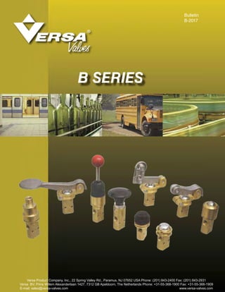
- 1. Bulletin B-2017 Versa Product Company, Inc., 22 Spring Valley Rd., Paramus, NJ 07652 USA Phone: (201) 843-2400 Fax: (201) 843-2931 Versa BV, Prins Willem Alexanderlaan 1427, 7312 GB Apeldoorn, The Netherlands Phone: +31-55-368-1900 Fax: +31-55-368-1909 E-mail: sales@versa-valves.com www.versa-valves.com B SERIES
- 2. 2 Normally Closed Normally Open Without Button Guard Panel Mtg. Not Panel Mtg. Panel Mtg. Not Panel Mtg. TWO WAY BlK-2209-P BlK-2209 BlK-2207-P BlK-2207 THREE WAY BlK-3209-P BlK-3209 BlK-3207-P BlK-3207 Normally Closed Normally Open With Button Guard Panel Mtg. Not Panel Mtg. Panel Mtg. Not Panel Mtg. TWO WAY BlK-2208-P BlK-2208 BlK-2206-P BlK-2206 THREE WAY BlK-3208-P BlK-3208 BlK-3206-P BlK-3206 • Pilot, Manual, and Mechanical Actuation • Plunger travels only 3/16” • Full 3/16” Flow Area • All Brass Bodies and Stainless Steel Plunger • Service: Pneumatic-vacuum to 200 psi. Two-way can be used for hydraulic pressures to 500 psi. • Leakproof: Uses standard “O” ring seals; fluorocarbon and low temperature seals available • High Cv; (Normally Closed: 0.6, Normally Open: 0.5) • Available with 1/8” NPT Threaded Ports in Valve Body or with O-ring Recessed Ports for Subplate or Manifold Mounting. (See page 7) Note: All Series “B” valves utilize the basic design and parts of the button-operated types shown below. Basic dimensions and parts lists shown on page 7. Those parts listed and dimensions shown for specific valve types, are required in addition to or in place of the basic parts and dimensions shown on page 7. Versa exercises diligence to assure that information contained in this catalog is correct, but does not accept responsibility for any errors or omissions. Versa also reserves the right to change or delete data or products at any time without prior notification. To be sure the data you require is correct, consult factory. PLAIN BUTTON WITHOUT GUARD: For palm, finger, knee, or straight-line mechanical operation. Can also be cam actuated if cam rise is gradual. Aluminum button is 3/16” above valve body, the distance required for full actuation. Nominal operating force is 3.75 lb. + .05 times line pressure. Suffix Options: —67 Stainless steel button —167 Body (and nuts where applicable), brass internals —68 Mtg. holes clear #10 screw and aluminum button electroless nickel plated. —155 Fluorocarbon seals —S Strong spring for applications with marginal lubrication. WITH GUARD: For fingertip or straight-line mechanical operation. Button is flush with extended guard to protect against accidental actuation. Aluminum button travels 3/16” for full actuation. Nominal operating force is 3.75 lb. + .05 times line pressure. Suffix Options: —67 Stainless steel button —68 Mtg. holes clear #10 screw —155 Fluorocarbon seals — 294B Rubber button cover Not Panel Mounting Panel Mounting Not Panel Mounting Panel Mounting —167 Body (and nuts where applicable), brass internals and aluminum button electroless nickel plated. —S Strong spring for applications with marginal lubrication. Panel Mounting with Rubber Button Cover Two-Way Types for bleeding pilots of larger valves, for bleeding cylinders or small pressure systems, operating air tools or motors, opening or closing air lines. Three-Way Types for controlling pilots or diaphragms of larger valves or small cylinders or any pressure system that is alternately pressurized and exhausted. Service: Pneumatic-vacuum to 200 psi (14 bar). Two way can be used for hydraulic pressures to 500 psi. BIK-3209-P-294B Shown BIK-3209-P Shown BIK-3209 Shown BIK-3208 Shown BIK-2208-P Shown 032017
- 3. 3 Normally Closed Normally Open Palm Button Panel Mtg*. Not Panel Mtg Panel Mtg*. Not Panel Mtg. TWO WAY BlK-2208-P-25B BlK-2208-25B BlK-2206-P-25B BlK-2206-25B THREE WAY BlK-3208-P-25B BlK-3208-25B BlK-3206-P-25B BlK-3206-25B Palm Lever Normally Closed Normally Open TWO WAY BLK-2208 BLK-2206 THREE WAY BLK-3208 BLK-3206 1 7 16 2 2 5 16 1 5 16 11 8 4 1 8 10˚ 1 5 16 1 1 8 NPT Port 113 16 DIA. 3 7 16 4302-65-125 KNOB (BLACK) 4302-65-125G KNOB (GREEN) 4302-65-125R KNOB (RED) 4302-65-125B KNOB BUTTON PALM BUTTON Large-diameter black plastic button is standard, for comfortable operation. Green Knob or Red Knob is available. See suffix options below. Nominal operating force is 3.75 lb. + .05 times line pressure. Suffix Options: —25BG Green Knob —167 Body (and nuts where applicable), brass internals —25BR Red Knob and aluminum button 2209-03-25B are —67 Stainless steel button electroless nickel plated. —68 Mtg. holes clear #10 screw —S Strong spring for applications with marginal —155 Fluorocarbon seals lubrication. *See page 7 for panel Mtg. dimensions. Suffix Options: —67 Stainless steel button —167 Body (and nuts where applicable), brass internals —68 Mtg. holes clear #10 screw and aluminum button electroless nickel plated. —155 Fluorocarbon seals —S Strong spring for applications with marginal lubrication. PALM LEVER Can be operated by hand or knee. A light touch is sufficient. Green knob or red knob is available. See Suffix options below. Bracket and Palm Lever is sub-assembly BA-3200-69L BLK-3208 Shown BIK-3208-25B Shown
- 4. 4 Hand Lever (Spring Return) Normally Closed Normally Open TWO WAY BHS-2208 BHS-2206 THREE WAY BHS-3208 BHS-3206 Hand Lever (Detented) Normally Closed Normally Open TWO WAY BHK-2208-S BHK-2206-S THREE WAY BHK-3208-S BHK-3206-S Ball Cam Normally Closed Normally Open TWO WAY BlK-2208-66 BlK-2206-66 THREE WAY BlK-3208-66 BlK-3206-66 P-1001-08 BALL 4302-19D GLAND SEAL 3209-23A BALL** 3209-18L LEVER CAP P-1003-10 BALL 3209-25 BUTTON 3209-24 HANDLE **BALL SHOWN IS SPRING RETURN TYPE IS 3209-23 TYPE - DETENT Hand Lever sub-assembly is BA-3200-69S (spring BHS type) BA-3200-69K (spring BHK type) 4 7 85 25° 213 16 1 41 Ø 3209-13 CAM CAP 3209-48 NUT P-1003-24 CAS BALL Ball Cam sub-assembly is BA-3200-66 Light force, offsetting the handle 25° from vertical, is sufficient to operate SPRING RETURN: Remains actuated only while handle is held in offset position. DETENTED: Once offset, handle will stay in position, springs back when pushed slightly out of position Can be operated by a cam or machine member from any angle, but pressure angle should not exceed 20° from vertical center line. HAND LEVER BALL CAM Suffix Options: —68 Mtg. holes clear #10 screw —S Strong spring for applications with marginal —155 Fluorocarbon seals lubrication. Std on detented type. —167 Body, brass internals, lever cap are electroless nickel plated Suffix Options: —68 Mtg. holes clear #10 screw —S Strong spring for applications with marginal —155 Fluorocarbon seals lubrication. —167 Body, brass internals, lever cap are electroless nickel plated Cam follower is hardened chrome alloy steel. BIK-3208-66 Shown BHK-3208-S Shown
- 5. 5 Cam Lever Normally Closed Normally Open TWO WAY BCK-2208 BCK-2206 THREE WAY BCK-3208 BCK-3206 Ball Cam With Overtravel Normally Closed Normally Open TWO WAY BlK-2208-66-18 BlK-2206-66-18 THREE WAY BlK-3208-66-18 BlK-3206-66-18 1/8" NPT (2 PORTS) TRAVEL 2 1 4 3 8 11 161 ø 7 8 1 81 IN 3209-15-18 Yoke Assm. 3209-06-18 Spring 3209-14-18 Cup Spacer PRR-3 Retaining Ring 3209-13-18 Cam Cap 3209-48 Locknut Ball Cam w/overtravel sub-assembly is BA-3200-66-18 OVER TRAVEL FULL OPEN TRAVEL OUT 1/8" NPT PANEL THICKNESS 1.0 3 16 3 16 9 16 MAX 9 16 5 8 3 31 32 19 32 11 4 5 8 Actuated by cam movement in either direction. Cam follower is hardened. Can be operated by a cam or machine member. Has 3/16” over-travel after full actuation. This valve can be panel mounted. Pressure angle should not exceed 15° from vertical center line. Cam follower is hardened 430F stainless steel. Suffix Options: —68 Mtg. holes clear #10 screw —S Strong spring for applications with marginal —155 Fluorocarbon seals lubrication. —167 Body, brass internals, cam cap are electroless nickel plated. Suffix Options: —67 Stainless steel button —167 Body, brass internals, bracket and aluminum —68 Mtg. holes clear #10 screw button are plated with electroless nickel. —155 Fluorocarbon seals —S Strong spring for applications with marginal lubrication. CAM LEVER BALL CAM WITH OVERTRAVEL Bracket and Cam Lever is sub-assembly BA-3200-40 BIK-3208-66-18 Shown BCK-3208 Shown
- 6. 6 Trip-Cam Lever Normally Closed Normally Open TWO WAY BCK-2208-35 BCK-2206-35 THREE WAY BCK-3208-35 BCK-3206-35 Pilot Normally Closed Normally Open TWO WAY BPS-2208 BPS-2206 THREE WAY BPS-3208 BPS-3206 Minimum Pilot Pressure required for Actuation (PSI) 18 20 22 24 26 28 30 32 34 36 If Inlet Pressure (PSI) is: 0-20 40 60 80 100 120 140 160 180 200 2¼ 1 1⅛ 3 ⅜ 5 161 1Ø Travel 3209-07 Piston 3209-11 Pilot Cap 3209-48 Nut P-1016-U13-11 “U” Cup Pilot Cap Sub-Assembly is BA-3200-64 33 8 1 41 ⅛ NPT Pilot Port Actuated by cam travel in one direction only. Overriding device prevents actuation on return stroke. Cam follower is hardened. Controlled by a low-pressure signal applied to a small pilot piston integrated into the valve. This actuates the valve. When the pressure is exhausted, the valve returns to the unactuated position. Pilot medium is separate from medium being controlled. Suffix Options: —67 Stainless steel button —167 Body, brass internals, bracket and aluminum —68 Mtg. holes clear #10 screw and aluminum button electroless nickel plated. —155 Fluorocarbon seals —S Strong spring for applications with marginal lubrication. Suffix Options: — 67 Brass and stainless steel internals — 167 Body, brass internals, pilot cap are — 68 Mtg. holes clear #10 screw electroless nickel plated. —155 Fluorocarbon seals — S Strong spring for applications with marginal lubrication. Increases pilot pressure by 45%. TRIP-CAM LEVER PILOT Bracket and Trip-Cam Lever is sub-assembly BA-3200-40-35. BPS-2208 Shown BCK-3208-35 Shown
- 7. 7 Basic Valve Kit Fluorocarbon Valve Kit Manual & Mechanical Pilot Manual & Mechanical Pilot 2 way NO B-2207 B-2207-P B-2207-155 B-2207-P-155 2 way NC B-2209 B-2209-P B-2209-155 B-2209-P-155 3 way NO B-3207 B-3207-P B-3207-155 B-3207-P-155 3 way NC B-3209 B-3209-P B-3209-155 B-3209-P-155 3209-48 Nut (2 req’d) 3209-51 Pin 2209-03 Button PSS-1032-03 Screw 2208-01 Body with Button Guard (Shown) 2209-01 Body without Button Guard (Shown) 2208-01P Body (Panel Mount.) with Guard (Shown) 2209-01P Body (Panel Mount.) without Guard 3209-47 Spring P-1000-05 O-Ring 2209-02 Plunger Two-Way (Shown) 3209-02 Plunger Three-Way (Dotted) P-1000-01 O-Ring Out ⅛” NPT In ⅛” NPT 1” -32 Thread On Panel Mount. Valve 7 * 16 3 16 Out ⅛” NPT Max Travel In ⅛” NPT Ø .159 THRU (2 MOUNTING HOLES) 3209-51 Pin 2209-03 Button PSS-1032-03 Screw 2206-01 Body with Button Guard (Shown) 2207-01 Body without Button Guard (Shown) 2206-01P Body (Panel Mount.) with Guard (Shown) 2207-01P Body (Panel Mount.) without Guard 3209-47 Spring P-1000-04 O-Ring 2207-02 Plunger Two-Way 3202-02 Plunger Three-Way (Dotted) P-1000-01 O-Ring 2207-05 Retainer 2207-03 Retainer P-1000-07 O-Ring NORMALLY OPENNORMALLY CLOSED 2 7 8 13 16 5 16 5 8 5 8 1 1 Flats Ø 1 41Ø * Maximum panel thickness is 7/16” except for valves without button guard. For theses, maximum panel thickness is 1/4”. 1 1 19 32 BASIC VALVE DIMENSIONS AND PARTS MANIFOLD MOUNTING TYPE Any of the standard Series “B” Valves can be supplied for manifold mounting. O-ring recessed ports are provided on one of the body. Valves can be grouped on a common multiple manifold, as shown below. A common inlet supplies all valves on the manifold. Custom designs are also available. Consult factory for information about types of multiple manifolds available. Repair Kits BIK-3218 Shown Manifold BM-4 Shown Valves & Manifold Shown Below 4) BIK-3219 1) BM-4
- 8. Versa has been supplying the oil and gas industry with pneumatic and hydraulic components for over 50 years. We have built a reputation for quality that is unsurpassed in the market for high performance solenoids, pneumatic relays, resets and pilot valves WARNINGS REGARDING THE DESIGN APPLICATION, INSTALLATION AND SERVICE OF VERSA PRODUCTS The warnings below must be read and reviewed before designing a system utilizing, installing, servicing, or removing a Versa product. Improper use, installation or servicing of a Versa product could create a hazard to personnel and property. DESIGN APPLICATION WARNINGS Versa products are intended for use where compressed air or industrial hydraulic fluids are present. For use with media other than specified or for non-industrial applications or other applications not within published specifications, consult Versa. Versa products are not inherently dangerous. They are only a component of a larger system. The system in which a Versa product is used must include adequate safeguards to prevent injury or damage in the event of system or product failure, whether this failure be of switches, regulators, cylinders, valves or any other system component. System designers must provide adequate warnings for each system in which a Versa product is utilized. These warnings, including those set forth herein, should be provided by the designer to those who will come in contact with the system. Where questions exist regarding the applicability of a Versa product to a given use, inquiries should be addressed directly to the manufacturer. Confirmation should be obtained directly from the manufacturer regarding any questioned application prior to proceeding. INSTALLATION, OPERATION AND SERVICE WARNINGS Do not install or service any Versa product on a system or machine without first depressurizing the system and turning off any air, fluid, or electricity to the system or machine. All applicable electrical, mechanical, and safety codes, as well as applicable governmental regulations and laws must be complied with when installing or servicing a Versa product. Versa products should only be installed or serviced by qualified, knowledgeable personnel who understand how these specific products are to be installed and operated. The individual must be familiar with the particular specifications, including specifications for temperature, pressure, lubrication, environment and filtration for the Versa product which is being installed or serviced. Specifications may be obtained upon request directly from Versa. If damages should occur to a Versa product, do not Operate the system containing the Versa product. Consult Versa for technical information. LIMITED WARRANTY DISCLAIMER AND LIMITATION OF REMEDIES Versa’s Series products are warranted to be free from defective material and workmanship for a period of ten years from the date of manufacture, provided said products are used in accordance with Versa specifications. Versa’s liability pursuant to that warranty is limited to the replacement of the Versa product proved to be defective provided the allegedly defective product is returned to Versa or its authorized distributor. Versa provides no other warranties, expressed or implied, except as stated above. There are no implied warranties of merchantability or fitness for a particular purpose. Versa’s liability for breach of warranty as herein stated is the only and exclusive remedy and in no event shall Versa be responsible or liable for incidental or consequential damages. Versa Products Company Inc. 22 Spring Valley Road Paramus, New Jersey 07652 USA Phone: 201-843-2400 Fax: 201-843-2931 Versa BV Prins Willem Alexanderlaan 1429 7321 GB Apeldoorn The Netherlands Phone: 01131-55-368-1900 Fax: 01131-55-368-1909 www.versa-valves.com email: sales@versa-valves.com