SlideShare una empresa de Scribd logo
1 de 26
Descargar para leer sin conexión
Panther
Installation instructions 


Transmitters PN-TX-MX8B (PN-T19-2)


IM-PN-TX103-A01-EN
Language: English (original)
CONTENTS
Chapter 1: CUSTOMER INFORMATION 3
Chapter 2: FUNCTIONAL SAFETY 5
Chapter 3: PRODUCT DESCRIPTION 7
Transmitter front 7
Transmitter back 7
Technical data 8
Frequency band 8
Chapter 4: INSTALLERS GUIDE 9
Start the transmitter 9
Switch the transmitter off 9
Logout 9
Register the transmitter in the receiver 10
Erase all transmitters from the receiver 11
Replace 11
Automatic shutdown 12
Show channel 13
Switch channel 13
Load select mode 14
Radio mode 17
Enter menu mode 18
Chapter 5: BATTERY GUIDE 19
Chapter 6: GUARANTEE, SERVICE, REPAIRS AND MAINTENANCE 21
Chapter 7: REGULATORY INFORMATION 22
Chapter 8: FREQUENT TERMS 24
Chapter 1: CUSTOMER INFORMATION
CHAPTER 1: CUSTOMER INFORMATION
 
THANK YOU FOR PURCHASING A TELE RADIO AB PRODUCT
 
READ ALL INSTRUCTIONS AND WARNINGS CAREFULLY BEFORE MOUNTING, INSTALLING
AND CONFIGURATING THE PRODUCTS.
 
These instructions are published by Tele Radio AB and are not subject to any guarantee. The
instructions may be removed or revised by Tele Radio AB at any time and without further notice.
Corrections and additions will be added to the latest version of the instructions.
 
IMPORTANT! These instructions are directed to installers. The instructions containing information
about the installation and configuration of the radio remote control unit on the machine are not
intended to be passed on to the end user. Only information that is needed to operate the machine
correctly by radio remote control may be passed on to the end user.
 
Tele Radio AB products are covered by a guarantee/warranty against material, construction or
manufacturing faults. During the guarantee/warranty period, Tele Radio AB may replace the product or
faulty parts. Work under guarantee/warranty must be carried out by Tele Radio AB or by an authorized
service center specified by Tele Radio AB. Contact your Tele Radio AB representative if you need
support or service.
 
©Tele Radio AB
Datavägen 21
SE-436 32 ASKIM
SWEDEN
Tel: +46-31-748 54 60
Fax: +46-31-68 54 64
www.tele-radio.com
- 3 -
WARNINGS & RESTRICTIONS
 
WARNING! Tele Radio AB remote controls are often built into wider applications. We recommend
that the system is equipped with a wired emergency stop where necessary.
 
NOTE! We recommend that the functionality of the stop button is tested on a regular basis (at least
after every 200 hours' use). Test the stop button by pressing it and pulling it out.
 
INSTALLING, CONNECTING AND MOUNTING
 n Only permit licensed or qualified personnel to install the product.
 n Switch off the power supply to the receiver before connecting the equipment.
 n Check that the power supply is connected to the correct connection terminal.
 n To utilize the safety of the system, use the stop relays in the safety circuitry of the object that you
want to control.
 n Do not use damaged cables. Cables must not hang loose.
 n Avoid installing in areas affected by strong vibrations.
 n Place the receiver well away from wind, damp and moisture.
 n Cable glands and vent plugs must face downwards to prevent water from gaining access.
 
THE USER
 n Only permit qualified personnel to access the transmitter and operate the equipment.
 n Make sure that the user follows the instructions.
 n Make sure that the user satisfies the age requirements in your country for operating the equip-
ment.
 n Make sure that the user is not under the influence of drugs, alcohol or medications.
 n Make sure that the user does not leave the transmitter unsupervised.
 n Make sure that the user always switches the transmitter off when it is not in use.
 n Make sure that the user has a clear view of the work area at all times.
 
MAINTENANCE
 n Use the stop button to start and switch off the transmitter as often as possible.
 n If error messages are shown, it is very important to find out what caused them.
 n If the stop button is mechanically damaged, contact your representative for service immediately.
 n Always contact your representative for service and maintenance work on the product.
 n Write down the serial numbers/ID codes of the receivers and transmitters used. This information
should be recorded in the “Settings document” for your product (download from our website).
 n Avoid registering transmitters in receivers where they are not being used.
 n Keep the safety instructions for future reference. Always download the configuration instruc-
tions from our website for the latest available version.
 
WEEE DIRECTIVE
 
This symbol means that inoperative electrical and electronic products must not be mixed
with household waste. The European Union has implemented a collection and recycling
system for which producers are responsible. For proper treatment, recovery and recycling,
please take this product to a designated collection point.
 
Tele Radio AB strives to minimize the use of hazardous materials, promotes reuse and recycling, and
reduces emissions to air, soil and water. When a commercially viable alternative is available, Tele Radio
AB strives to restrict or eliminate substances and materials that pose an environmental, health or safety
risk.
- 4 -
Chapter 2: FUNCTIONAL SAFETY
CHAPTER 2: FUNCTIONAL SAFETY
 
NOTE! The information in this section applies only to the products specified below.
 
Safety function
The safety-related stop function in the radio system complies with EN 13849-1:2008 Category 3 PLd.
The stop relays on the receiver unit are controlled by the stop button on the transmitter unit. When the
stop button is pressed, the stop relays break the power to the safety-related application. The complete
end-user system, including the radio system, enters a safe state. The maximum response time for the
safety-related stop function is 500ms.
 
Applicable products
The following transmitter and receiver units are designed to comply with the appointed safety
requirements:
Receivers: PN-R15-1, PN-R15-2, PN-R15-7, PN-R15-8
Transmitter: PN-T19-2
 
NOTE! Both the receiver and the transmitter used in the specific end-user system must be compliant.
 
Installation
The stop relays on the receiver unit must be correctly installed on the end-user system, to ensure that
opened/deactivated stop relays interrupt the power to the safety-related application. The safety level of
the stop function can only be credited when used in a complete end-user system that complies with EN
13849-1:2008 Category 3 PLd.
 
Configuration
The default configuration of the receiver unit complies with the appointed safety requirements. Any
reconfiguration that breaches the safety requirements will be indicated by a LED on the main board of
the receiver unit. Before commissioning the radio system, the installer must check the LED indication.
 
Function LED Status Indicates
PLd status LED (red) ON Not compliant with PLd
OFF Compliant with PLd
 
R1 R2R5R5R5 R4R31
2
R5
1. Stop relays
2. PLd status LED


- 5 -
Chapter 2: FUNCTIONAL SAFETY
WARNING! All safety-related parameters must be configured as follows in order to comply with the
appointed safety requirements:
 
 n The system must be configured in continuous radio mode
 n All relays must be switched off when the radio link is down
 n The radio link timeout must be set to a maximum of 500ms
 n The login/logout function must be activated
 n The Custom ID setting must be deactivated, i.e. the receiver must always use the unique trans-
mitter ID code
- 6 -
Chapter 3: PRODUCT DESCRIPTION
CHAPTER 3: PRODUCT DESCRIPTION
 
TRANSMITTER FRONT
 
1
2
3
4
11
6
5
7
13
12
14
8
9
10
15
 1. Rubber cover
 2. Stop button
 3. LED 2 (red)
 4. LED 4 (red)
 5. LED 1 (red)
 6. LED 3 (red)
 7. Top LED (red, green)
 8. Button 1
 9. Button 3
 10. Button 5
 11. Button 7 – left start button
 12. Button 2
 13. Button 4
 14. Button 6
 15. Button 8 – right start button
 
TRANSMITTER BACK
 
1
3
4
5
2
 1. Rubber cover
 2. Replace ID label (placed under rubber cover)
 3. Stop button
 4. Battery pack
 5. Product label (placed under battery pack)
- 7 -
TECHNICAL DATA
 
Number of buttons 8 x 2-step buttons
Battery 3 x 1.5V AAA / LR03 in battery pack D4-3
On/off switch No
Radio communication Simplex
Dimensions 85 x 193 x 43 mm / 3.4 x 7.7 x 1.7 in
Weight 300 g / 0.7 lbs
Frequency band 2405–2480 MHz
Number of channels 16 (channel 11–26)
Operating time (continuous usage) Approximately 100 h. with alkaline (depending on settings)
IP code 65
Operating temperature -20 – +55 °C / -4 – +130 °F
 
FREQUENCY BAND
 
Channel Frequency
11 2405 MHz
12 2410 MHz
13 2415 MHz
14 2420 MHz
15 2425 MHz
16 2430 MHz
17 2435 MHz
18 2440 MHz
19 2445 MHz
20 2450 MHz
21 2455 MHz
22 2460 MHz
23 2465 MHz
24 2470 MHz
25 2475 MHz
26 2480 MHz
- 8 -
Chapter 4: INSTALLERS GUIDE
CHAPTER 4: INSTALLERS GUIDE
 
START THE TRANSMITTER
 
 1. Make sure that the stop button is pressed.
 2. Twist and pull out the stop button.
The top LED lights (green when the battery capacity is good, red when the battery capacity is
poor), LEDs 3 and 4 flash (red).
 3. Press buttons 7 and 8 at the same time for at least 1 second.
LEDs 3 and 4 light (red).
 4. Release buttons 7 and 8.
LEDs 3 and 4 go out. The top LED flashes (green).
 
SWITCH THE TRANSMITTER OFF
 
 1. Press the stop button.
 
NOTE! When the transmitter is active and the stop button is pressed, all relays go off.
 
LOGOUT
 
WARNING! For the logout function to work, BOTH the receiver and the transmitter must have the
logout function activated and be set to continuous radio mode.
 
NOTE! You cannot activate/deactivate the logout function in the transmitter or the receiver. Contact
your representative for assistance.
 
For this transmitter the logout function is activated by default.
 
Quick logout
 
NOTE! Quick logout can only be performed when the transmitter is on and the radio link is up.
 
 1. Press button 7. Keep pressed.
 2. Press the stop button.
The top LED lights (red).
The transmitter takes approximately 3 seconds to logout. The transmitter switches off.
 
Logout from receiver
 
This logout option is used when a lost or damaged transmitter must be logged out from the receiver.
 
 1. Press the receiver Select button.
LED 10 lights (orange).
 2. Keep pressed (for more than 4 seconds).
LED 10 goes off.
The transmitter is now logged off. Any other registered transmitter can log in.
- 9 -
Logout from menu mode
 
This logout option is mainly used when the button for quick logout is used by another function.
 
 1. Make sure that the stop button is pressed.
 2. Press button 8. Keep pressed.
 3. Twist and pull out the stop button.
 4. Release button 8.
The top LED flashes (green).
 5. WITHIN 1 MINUTE OF PULLING OUT THE STOP BUTTON:
Enter the code: 1-2-3-4 (press buttons 1, 2, 3, 4). LEDs 1–4 light up (red). If the code is invalid,
the transmitter switches off. When the code is accepted, the top LED flashes (green). LEDs 1–4
flash (red).
 6. WITHIN 1 MINUTE OF ENTERING THE CODE:
Press button 7.
The top LED flashes (red).
The transmitter takes approximately 10 seconds to logout. The transmitter switches off.
 
REGISTER THE TRANSMITTER IN THE RECEIVER
 
WARNING! Only keep the transmitters that you intend to use registered in the receivers.
 
NOTE! To establish a radio link between the transmitter and the receiver, both units must be set to the
same radio mode.
 
 1. Make sure that the stop button is pressed.
 2. Twist and pull out the stop button.
The top LED lights (green when the battery capacity is good, red when the battery capacity is
poor), LEDs 3 and 4 flash (red).
 3. Press buttons 7 and 8 at the same time for at least 1 second.
LEDs 3 and 4 light (red).
 4. Release buttons 7 and 8.
LEDs 3 and 4 go out. The top LED flashes (green).
 5. Press the receiver Function button.
The function LED lights (red).
 6. Press the receiver Select button.
All relay LEDs light (red).
 7. Press buttons 1 and 2. Keep pressed.
All relay LEDs light (red). All relay LEDs flash 2 times (red).
 
- 10 -
 8. Release buttons 1 and 2.
All relay LEDs flash 1 time (red).
The transmitter is registered.
 
If no transmitter is found within approximately 10 seconds, the receiver exits to normal operation.
 
ERASE ALL TRANSMITTERS FROM THE RECEIVER
 
 1. Press the receiver Function button.
The function LED lights (red).
 2. Press the receiver Select button. Keep pressed (at least 4 seconds).
All relay LEDs light (red). All relay LEDs go out.
 3. Release the receiver Select button.
All transmitters are erased from the receiver.
 
If the function LED flashes (red), one or more transmitters are still registered in the receiver.
 
REPLACE
 
It is possible to replace a registered transmitter with another transmitter without having access to the
receiver. Use the new transmitter that is replacing the old transmitter.
 
 1. Make sure that the stop button is pressed.
 2. Press button 8. Keep pressed.
 3. Twist and pull out the stop button.
 4. Release button 8.
The top LED flashes (green).
 5. WITHIN 1 MINUTE OF PULLING OUT THE STOP BUTTON:
Enter the code: 1-2-3-4 (press buttons 1, 2, 3, 4). LEDs 1–4 light up (red). If the code is invalid,
the transmitter switches off. When the code is accepted, the top LED flashes (green). LEDs 1–4
flash (red).
 6. WITHIN 1 MINUTE OF ENTERING THE CODE:
Press button 3.
The top LED lights (green). LED 2 flashes (red).
 7. Enter the Replace ID (a maximum of 11 digits) for the transmitter being replaced by pressing the
transmitter buttons.
LED 3 lights (red) when one or more digits have been entered.
LEDs 3 and 4 light (red) when the maximum number of digits (11) have been entered.
 
(000000)
Replace ID: 000000000
IMPORTANT! When entering the last digit in the code, keep
that button pressed until the stop button has been pressed.
IMPORTANT! The Replace ID label is placed in the back of the
transmitter. Remove the rubber cover.
- 11 -
 8. Press the stop button. Release the last Replace ID button.
After approximately 10 seconds the transmitter switches off.
 
  If the replace procedure fails, press the stop button and start again.
 
AUTOMATIC SHUTDOWN
 
NOTE! Only for continuous radio mode.
 
Automatic shutdown can save battery capacity by automatically switching the transmitter off following a
preset period of inactivity.
 
Setting the automatic shutdown time
 
 1. Make sure that the stop button is pressed.
 2. Press button 8. Keep pressed.
 3. Twist and pull out the stop button.
 4. Release button 8.
The top LED flashes (green).
 5. WITHIN 1 MINUTE OF PULLING OUT THE STOP BUTTON:
Enter the code: 1-2-3-4 (press buttons 1, 2, 3, 4). LEDs 1–4 light up (red). If the code is invalid,
the transmitter switches off. When the code is accepted, the top LED flashes (green). LEDs 1–4
flash (red).
 6. WITHIN 1 MINUTE OF ENTERING THE CODE:
Press button 5.
The top LED lights (green). LED 2 flashes (red).
 7. Select the automatic shutdown time by pressing a button according to the following table.
The top LED flashes 3 times (green). The transmitter switches off.
 
Press... Automatic shutdown time after...
button 1 3 minutes
button 2 6 minutes
button 3 12 minutes
button 7 No automatic shutdown
- 12 -
SHOW CHANNEL
 
 1. Make sure that the stop button is pressed.
 2. Press button 8. Keep pressed.
 3. Twist and pull out the stop button.
 4. Release button 8.
The top LED flashes (green).
 5. WITHIN 1 MINUTE OF PULLING OUT THE STOP BUTTON:
Enter the code: 1-2-3-4 (press buttons 1, 2, 3, 4). LEDs 1–4 light up (red). If the code is invalid,
the transmitter switches off. When the code is accepted, the top LED flashes (green). LEDs 1–4
flash (red).
 6. WITHIN 1 MINUTE OF ENTERING THE CODE:
Press button 4.
The top LED lights (green).
 7. The selected channel will be indicated as follows:
LED 1 flashes (red) the number of times corresponding to the first digit. LED 2 flashes (red) the
number of times corresponding to the second digit.
For example channel 23: LED 1 will flash 2 times, LED 2 will flash 3 times.
 
SWITCH CHANNEL
 
 1. Make sure that the stop button is pressed.
 2. Press button 8. Keep pressed.
 3. Twist and pull out the stop button.
 4. Release button 8.
The top LED flashes (green).
 5. WITHIN 1 MINUTE OF PULLING OUT THE STOP BUTTON:
Enter the code: 1-2-3-4 (press buttons 1, 2, 3, 4). LEDs 1–4 light up (red). If the code is invalid,
the transmitter switches off. When the code is accepted, the top LED flashes (green). LEDs 1–4
flash (red).
 6. WITHIN 1 MINUTE OF ENTERING THE CODE:
Press button 8. Keep pressed.
 7. Press button 4. Release.
 8. Release button 8.
The top LED lights (green). LED 2 (red) flashes.
 9. Select channel 11–26 according to the following table.
LED 3 lights (red) when a valid digit has been entered.
LEDs 3 and 4 light (red) when two valid digits have been entered.
The top LED flashes (green) 3 times. The transmitter switches off.
 
- 13 -
For example channel 20: Press button 2 for the first digit. For zero, press button 8, keep pressed, press
button 4, release button 4, release button 8.
 
Press... for digit...
button 1 1
button 2 2
button 3 3
button 4 4
button 5 5
button 6 6
button 8 (shift) + button 1 7
button 8 (shift) + button 2 8
button 8 (shift) + button 3 9
button 8 (shift) + button 4 0
 
LOAD SELECT MODE
 
NOTE! Only for continuous radio mode.
 
 1. Make sure that the stop button is pressed.
 2. Press button 8. Keep pressed.
 3. Twist and pull out the stop button.
 4. Release button 8.
The top LED flashes (green).
 5. WITHIN 1 MINUTE OF PULLING OUT THE STOP BUTTON:
Enter the code: 1-2-3-4 (press buttons 1, 2, 3, 4). LEDs 1–4 light up (red). If the code is invalid,
the transmitter switches off. When the code is accepted, the top LED flashes (green). LEDs 1–4
flash (red).
 6. WITHIN 1 MINUTE OF ENTERING THE CODE:
Press button 6.
The top LED lights (green). LED 2 flashes (red).
 7. Select a Load select mode by pressing a button according to the following table.
The top LED flashes (green) 3 times. The transmitter switches off.
 
Press... for Load select mode... with this load selected at start-up
button 7 0 (default) none
button 1 1 A
button 2 2 A
button 3 3 A
button 4 4 A
 
- 14 -
LOAD SELECT MODE 0-4
 
Load select mode 0 Load select mode 1
   
   
Load select mode 2 Load select mode 3
   
 
Load select mode 4  
   
 
- 15 -
LOAD AT START-UP
 
NOTE! Be sure to select Load select mode BEFORE selecting Load at start-up.
 
 1. Make sure that the stop button is pressed.
 2. Press button 8. Keep pressed.
 3. Twist and pull out the stop button.
 4. Release button 8.
The top LED flashes (green).
 5. WITHIN 1 MINUTE OF PULLING OUT THE STOP BUTTON:
Enter the code: 1-2-3-4 (press buttons 1, 2, 3, 4). LEDs 1–4 light up (red). If the code is invalid,
the transmitter switches off. When the code is accepted, the top LED flashes (green). LEDs 1–4
flash (red).
 6. WITHIN 1 MINUTE OF ENTERING THE CODE:
Press button 8. Keep pressed.
 7. Press button 6. Release.
 8. Release button 8.
The top LED lights (green). LED 2 flashes (red).
 9. Select Load at start-up by pressing a button according to the following table.
The top LED flashes (green) 3 times. The transmitter switches off.
Press... for Load at start-up...
button 7 none
button 1 A
button 2 B
button 3 A+B
- 16 -
RADIO MODE
 
NOTE! To establish a radio link between the transmitter and the receiver, both units must be set to the
same radio mode.
 
This transmitter is set to continuous radio mode by default. The transmitter starts to transmit
continuously as soon as it is started. The radio transmission ends when the stop button is pressed.
When the system is in continuous radio mode, buttons 7 and 8 are used as start buttons.
 
Note that some functions are only available when the products are transmitting continuously. Those
functions are marked: "Only for continuous radio mode".
 
To switch radio mode in the receiver, select an Operating mode that supports continuous/
discontinuous radio mode, depending on your preference. To switch radio mode in the transmitter, see
"Switch radio mode in transmitter" on the next page.
 
SWITCH RADIO MODE IN TRANSMITTER
 
NOTE! Be sure to set the receiver to an Operating mode that supports continuous/discontinuous Radio
mode, depending on your preference, before following the instructions below.
 
 1. Make sure that the stop button is pressed.
 2. Press button 8. Keep pressed.
 3. Twist and pull out the stop button.
 4. Release button 8.
The top LED flashes (green).
 5. WITHIN 1 MINUTE OF PULLING OUT THE STOP BUTTON:
Enter the code: 1-2-3-4 (press buttons 1, 2, 3, 4). LEDs 1–4 light up (red). If the code is invalid,
the transmitter switches off. When the code is accepted, the top LED flashes (green). LEDs 1–4
flash (red).
 6. WITHIN 1 MINUTE OF ENTERING THE CODE:
Press button 1.
The top LED lights (green). LED 2 flashes (red).
 7. Select radio mode by pressing a button according to the following table.
The top LED flashes (green) 3 times. The transmitter switches off.
 
Press... for Radio mode...
button 1 continuous (default)
button 2 discontinuous
- 17 -
ENTER MENU MODE
 
 1. Make sure that the stop button is pressed.
 2. Press button 8. Keep pressed.
 3. Twist and pull out the stop button.
 4. Release button 8.
The top LED flashes (green).
 5. WITHIN 1 MINUTE OF PULLING OUT THE STOP BUTTON:
Enter the code: 1-2-3-4 (press buttons 1, 2, 3, 4). LEDs 1–4 light up (red). If the code is invalid,
the transmitter switches off. When the code is accepted, the top LED flashes (green). LEDs 1–4
flash (red).
 6. WITHIN 1 MINUTE OF ENTERING THE CODE:
Enter a menu by pressing the buttons according to the image below.
   
1
3
5
6
4
2
7
 1. Radio mode
 2. Replace
 3. Show channel
 4. Automatic shutdown
 5. Load select mode
 6. Logout
 7. Shift button
Shift + 3. Switch channel
Shift + 5. Load at start-up
- 18 -
Chapter 5: BATTERY GUIDE
CHAPTER 5: BATTERY GUIDE
 
NOTE! Electronics and batteries must be physically separated before disposal. Make sure that
electronics or batteries are not disposed of in household waste.
 
NOTE! When approximately 10 % of battery capacity remains, the top LED lights red.
 
BATTERY INFORMATION
 
NOTE! Two different battery types – D4-2 and D4-3 – are available for use in the transmitter. The
transmitter is supplied with D4-3 batteries.
 
  D4-2 D4-3
Type of battery Replaceable, rechargeable lithium-ion
battery
Replaceable battery pack with 3 x
1.5V AAA / LR03 batteries
Operating time Approximately 150 h. (depending on
settings)
Approximately 100 h. with alkaline
(depending on settings)
Charge Charge in the Tele Radio AB charger
unit
Do not charge in the Tele Radio AB
charger unit. Replace the batteries
inside the battery pack.
Charging temperature 0 – +45 °C / +32 – +113 °F Not applicable
 
BATTERY PRECAUTIONS
 
Observe the following general battery warnings:
 n As batteries contain flammable substances such as lithium or other organic solvents, they may
cause heating, rupture or ignition.
 n Risk of explosion if a battery is replaced with the incorrect type of battery.
 n Do not short circuit, disassemble, deform or heat batteries.
 n Never try to charge a visibly damaged or frozen battery.
 n Keep batteries out of reach of small children. If a child swallows a battery, seek immediate med-
ical attention.
 n Avoid direct soldering to batteries.
 n When discarding batteries, insulate the + and - terminals of batteries with insulating/masking
tape. Do not put multiple batteries into the same plastic bag.
 n When improperly disposed, batteries may short circuit, causing them to become hot, burst or
ignite.
 n Store in a cool place. Keep batteries away from direct sunlight, high temperatures, and high
humidity.
 n Do not throw batteries onto fire.
- 19 -
CHANGE BATTERIES
 
Change batteries in battery pack D4-3
 
WARNING! Do not charge battery pack D4-3 in the Tele Radio AB charger unit or in any other
charger.
 
 1. Remove the battery pack from the back of the transmitter.
 2. Open the battery pack.
 3. Replace the 3 x 1.5V AAA / LR03 batteries. Use alkaline batteries for optimal performance.
 4. Put the battery pack back in the transmitter.
- 20 -
Chapter 6: GUARANTEE, SERVICE, REPAIRS AND MAINTENANCE
CHAPTER 6: GUARANTEE, SERVICE, REPAIRS AND
MAINTENANCE
 
Tele Radio AB products are covered by a guarantee/warranty against material, construction and
manufacturing faults. During the guarantee/warranty period, Tele Radio AB may replace the product or
faulty parts. Work under guarantee/warranty must be carried out by Tele Radio AB or by an authorized
service centre specified by Tele Radio AB.
 
The following are not covered by the guarantee/warranty:
 n Faults resulting from normal wear and tear
 n Parts of a consumable nature
 n Products that have been subject to unauthorized modifications
 n Faults resulting from incorrect installation and use
 n Damp and water damage
 
Maintenance:
 n Repairs and maintenance must be carried out by qualified personnel
 n Use spare parts from Tele Radio AB only
 n Contact your representative if you require service or other assistance
 n Keep the product in a dry, clean place
 n Keep contacts and antennas clean
 n Wipe off dust using a slightly damp, clean cloth
 
WARNING! Never use cleaning solutions or high-pressure water.
- 21 -
Chapter 7: REGULATORY INFORMATION
CHAPTER 7: REGULATORY INFORMATION
 
CE MARKING
 
This product is in compliance with the essential requirements of directive 1995/5/EC of the European
Parliament and of the Council. Latest version of the Declaration of Conformity can be downloaded from
the Tele Radio AB website.
 
FCC STATEMENT
 
This device complies with part 15 of the FCC Rules. Operation is subject to the following two
conditions: (1) This device may not cause harmful interference, and (2) this device must accept any
interference received, including interference that may cause undesired operation.
 
Changes or modifications not expressly approved by the party responsible for compliance could void
the user’s authority to operate the equipment.
 
This equipment has been tested and found to comply with the limits for a Class B digital device, pursuant
to part 15 of the FCC Rules. These limits are designed to provide reasonable protection against harmful
interference in a residential installation. This equipment generates uses and can radiate radio frequency
energy and, if not installed and used in accordance with the instructions, may cause harmful interference
to radio communications. However there is no guarantee that interference will not occur in a particular
installation. If this equipment does cause harmful interference to radio or television reception, which can
be determined by turning the equipment off and on, the user is encouraged to try to correct the
interference by one or more of the following measures:
 
–Reorient or relocate the receiving antenna.
–Increase the separation between the equipment and receiver.
–Connect the equipment into an outlet on a circuit different from that to which the receiver is
connected.
–Consult the dealer or an experienced radio/TV technician for help.
 
To satisfy FCC RF exposure requirements, a separation distance of 20 cm or more should be maintained
between the antenna of this device and persons during device operation.
To ensure compliance, operations at closer than this distance is not recommended.
 
IC STATEMENT
 
This product complies with Industry Canada's licence-exempt RSSs. Operation is subject to the
following two conditions:
(1) This device may not cause interference; and
(2) This device must accept any interference, including interference that may cause undesired operation
of device.
 
Le présent appareil est conforme aux CNR d'Industrie Canada applicables aux appareils radio exempts
de licence. L'exploitationest autorisée aux deux conditions suivantes : (1) l'appareil ne doit pas produire
de brouillage, et (2) l'utilisateur de l'appareil doit accepter tout brouillage radioélectrique subi, même si
le brouillage est susceptible d'en compromettre le fonctionnement.
 
To satisfy IC RF exposure requirements, a separation distance of 20 cm or more should be maintained
between the antenna of this device and persons during device operation. To ensure compliance,
operations at closer than this distance is not recommended.
 
- 22 -
Chapter 7: REGULATORY INFORMATION
Les antennes installées doivent être situées de facon à ce que la population ne puisse y être exposée à
une distance de moin de 20 cm. Installer les antennes de facon à ce que le personnel ne puisse
approcher à 20 cm ou moins de la position centrale de l'antenne. La FCC des éltats-unis stipule que cet
appareil doit être en tout temps éloigné d'au moins 20 cm personnes pendant son functionnement.
- 23 -
Chapter 8: FREQUENT TERMS
CHAPTER 8: FREQUENT TERMS
 
Configuration ID Numerical code stored in both the transmitter and receiver unit. The receiver unit
can only be controlled by a transmitter with the correct configuration ID.
   
Continuous radio
mode
When in continuous radio mode the transmitter unit transmits continuously when it
is switched on.
   
Custom ID Numerical code stored in the transmitter unit, used to replace the unique ID code.
One or several transmitter units can be configured with the same custom ID and the
receiver will recognise them all as the same transmitter unit.
   
Discontinuous
radio mode
When in discontinuous radio mode the transmitter unit transmits whenever it is
switched on and a button is pressed. The transmission is interrupted when all but-
tons are released.
   
Function relay Standard relay, controlled by the buttons on the transmitter unit.
   
Interlocking Prevents a component from functioning when another component is functioning or
operating in a particular way.
   
Latching relay
functionality
The relay becomes active every time you press a button and remains active until the
button is pressed again.
   
Load select mode One or more Load select modes are stored in the transmitter unit. Activating a spe-
cific Load select mode results in a group of preselected relays on the receiver unit,
which may be controlled from the transmitter unit.
   
Momentary relay
functionality
The relay will only be active while a button is pressed on the transmitter. When the
button is released, the relay will no longer be active.
   
On relay Relay that is active when the receiver unit is operating and a radio link is established,
regardless of whether any other relays are active.
   
Operating mode One or more operating modes are stored in the receiver unit. Each operating mode
describes which relays on the receiver unit are controlled when specific buttons on
the transmitter unit are pressed.
   
Replace ID Numerical code used to identify the transmitter during the Replace procedure.
   
Stop relay Safety related relay controlled by the stop button on the receiver. Intended to inter-
rupt the power supply to a safety application controlled by the receiver unit.
   
Work relay Relay that is active when any other specified relay(s) on the receiver unit is/are act-
ive.
   
Zero position
check
Security function ensuring that potentially active buttons/joysticks upon start up or
lost/found radio links must be in the zero position before the system can be used to
avoid unplanned movements of the controlled object.
- 24 -


(This page has intentionally been left blank)


- 25 -
This installation instruction is subject to change without prior notice.
Download the latest installation instruction from www.tele-radio.com

Más contenido relacionado

La actualidad más candente

Advanced motion controls azbdc40a8
Advanced motion controls azbdc40a8Advanced motion controls azbdc40a8
Advanced motion controls azbdc40a8Electromate
 
Advanced motion controls be30a8i
Advanced motion controls be30a8iAdvanced motion controls be30a8i
Advanced motion controls be30a8iElectromate
 
Advanced motion controls azbe40a8
Advanced motion controls azbe40a8Advanced motion controls azbe40a8
Advanced motion controls azbe40a8Electromate
 
Ionnic Switching Systems
Ionnic Switching SystemsIonnic Switching Systems
Ionnic Switching SystemsRimsky Cheng
 
R38 Controller
R38 ControllerR38 Controller
R38 ControllerJoseph
 
Advanced motion controls azbh6a8
Advanced motion controls azbh6a8Advanced motion controls azbh6a8
Advanced motion controls azbh6a8Electromate
 
Advanced motion controls az60a8
Advanced motion controls az60a8Advanced motion controls az60a8
Advanced motion controls az60a8Electromate
 
Advanced motion controls azb40a8
Advanced motion controls azb40a8Advanced motion controls azb40a8
Advanced motion controls azb40a8Electromate
 
Advanced motions control 16a20ac
Advanced motions control 16a20acAdvanced motions control 16a20ac
Advanced motions control 16a20acElectromate
 
Advanced motion controls azbdc60a8
Advanced motion controls azbdc60a8Advanced motion controls azbdc60a8
Advanced motion controls azbdc60a8Electromate
 
Advanced motion controls se25a40ac
Advanced motion controls se25a40acAdvanced motion controls se25a40ac
Advanced motion controls se25a40acElectromate
 
Advanced motion controls se25a40
Advanced motion controls se25a40Advanced motion controls se25a40
Advanced motion controls se25a40Electromate
 
Advanced motion controls be40a8i
Advanced motion controls be40a8iAdvanced motion controls be40a8i
Advanced motion controls be40a8iElectromate
 
Advanced motion controls 30a20ac
Advanced motion controls 30a20acAdvanced motion controls 30a20ac
Advanced motion controls 30a20acElectromate
 
Advanced motion controls az40a8
Advanced motion controls az40a8Advanced motion controls az40a8
Advanced motion controls az40a8Electromate
 
Sl 28200 emerson
Sl 28200 emersonSl 28200 emerson
Sl 28200 emersonmoy725
 
Applied motion products stm datasheet
Applied motion products stm datasheetApplied motion products stm datasheet
Applied motion products stm datasheetElectromate
 

La actualidad más candente (18)

Advanced motion controls azbdc40a8
Advanced motion controls azbdc40a8Advanced motion controls azbdc40a8
Advanced motion controls azbdc40a8
 
Advanced motion controls be30a8i
Advanced motion controls be30a8iAdvanced motion controls be30a8i
Advanced motion controls be30a8i
 
Advanced motion controls azbe40a8
Advanced motion controls azbe40a8Advanced motion controls azbe40a8
Advanced motion controls azbe40a8
 
Ionnic Switching Systems
Ionnic Switching SystemsIonnic Switching Systems
Ionnic Switching Systems
 
R38 Controller
R38 ControllerR38 Controller
R38 Controller
 
Advanced motion controls azbh6a8
Advanced motion controls azbh6a8Advanced motion controls azbh6a8
Advanced motion controls azbh6a8
 
Advanced motion controls az60a8
Advanced motion controls az60a8Advanced motion controls az60a8
Advanced motion controls az60a8
 
Advanced motion controls azb40a8
Advanced motion controls azb40a8Advanced motion controls azb40a8
Advanced motion controls azb40a8
 
Advanced motions control 16a20ac
Advanced motions control 16a20acAdvanced motions control 16a20ac
Advanced motions control 16a20ac
 
Advanced motion controls azbdc60a8
Advanced motion controls azbdc60a8Advanced motion controls azbdc60a8
Advanced motion controls azbdc60a8
 
Advanced motion controls se25a40ac
Advanced motion controls se25a40acAdvanced motion controls se25a40ac
Advanced motion controls se25a40ac
 
Advanced motion controls se25a40
Advanced motion controls se25a40Advanced motion controls se25a40
Advanced motion controls se25a40
 
Advanced motion controls be40a8i
Advanced motion controls be40a8iAdvanced motion controls be40a8i
Advanced motion controls be40a8i
 
Advanced motion controls 30a20ac
Advanced motion controls 30a20acAdvanced motion controls 30a20ac
Advanced motion controls 30a20ac
 
Vfd l m-en_20030522
Vfd l m-en_20030522Vfd l m-en_20030522
Vfd l m-en_20030522
 
Advanced motion controls az40a8
Advanced motion controls az40a8Advanced motion controls az40a8
Advanced motion controls az40a8
 
Sl 28200 emerson
Sl 28200 emersonSl 28200 emerson
Sl 28200 emerson
 
Applied motion products stm datasheet
Applied motion products stm datasheetApplied motion products stm datasheet
Applied motion products stm datasheet
 

Similar a Manual ponte rolante_im-pn-tx103-a01-en

Similar a Manual ponte rolante_im-pn-tx103-a01-en (20)

Manual de la Mezcladora SoundCraft Notepad -12Fx
Manual de la Mezcladora SoundCraft Notepad -12FxManual de la Mezcladora SoundCraft Notepad -12Fx
Manual de la Mezcladora SoundCraft Notepad -12Fx
 
User manual-475876
User manual-475876User manual-475876
User manual-475876
 
SenseTek Fireray 3000 installers handbook
SenseTek Fireray 3000 installers handbookSenseTek Fireray 3000 installers handbook
SenseTek Fireray 3000 installers handbook
 
Liquid Nitrogen Pump Cooling System
Liquid Nitrogen Pump Cooling SystemLiquid Nitrogen Pump Cooling System
Liquid Nitrogen Pump Cooling System
 
CATV Optical Transmitter
CATV Optical TransmitterCATV Optical Transmitter
CATV Optical Transmitter
 
Widom smart dimmer
Widom smart dimmerWidom smart dimmer
Widom smart dimmer
 
Manual smart TE dimmer Z-Wave -Widom
Manual  smart TE dimmer Z-Wave -WidomManual  smart TE dimmer Z-Wave -Widom
Manual smart TE dimmer Z-Wave -Widom
 
Regülatör
RegülatörRegülatör
Regülatör
 
Tx7201 zone monitor module
Tx7201 zone monitor moduleTx7201 zone monitor module
Tx7201 zone monitor module
 
sharp_14mn10_ch_sn-000.pptx
sharp_14mn10_ch_sn-000.pptxsharp_14mn10_ch_sn-000.pptx
sharp_14mn10_ch_sn-000.pptx
 
MA-2402-Manual-127240.pdf
MA-2402-Manual-127240.pdfMA-2402-Manual-127240.pdf
MA-2402-Manual-127240.pdf
 
Delta vfd lfrekv
Delta vfd lfrekvDelta vfd lfrekv
Delta vfd lfrekv
 
Drone jammer user manual
Drone jammer user manualDrone jammer user manual
Drone jammer user manual
 
14269179.pdf
14269179.pdf14269179.pdf
14269179.pdf
 
L03.1 l aa tv philips
L03.1 l aa tv philipsL03.1 l aa tv philips
L03.1 l aa tv philips
 
Smart DP Transmitter with Remote Seal
Smart DP Transmitter with Remote SealSmart DP Transmitter with Remote Seal
Smart DP Transmitter with Remote Seal
 
t v color Panasonic Tc 20 29-g12p
t v color Panasonic Tc 20 29-g12pt v color Panasonic Tc 20 29-g12p
t v color Panasonic Tc 20 29-g12p
 
Ex rc1 spec-en_1215
Ex rc1 spec-en_1215Ex rc1 spec-en_1215
Ex rc1 spec-en_1215
 
Widom Relay withdry contact_en
Widom Relay withdry contact_enWidom Relay withdry contact_en
Widom Relay withdry contact_en
 
718001 000 en
718001 000 en718001 000 en
718001 000 en
 

Último

Introduction to Machine Learning Unit-3 for II MECH
Introduction to Machine Learning Unit-3 for II MECHIntroduction to Machine Learning Unit-3 for II MECH
Introduction to Machine Learning Unit-3 for II MECHC Sai Kiran
 
Call Girls Delhi {Jodhpur} 9711199012 high profile service
Call Girls Delhi {Jodhpur} 9711199012 high profile serviceCall Girls Delhi {Jodhpur} 9711199012 high profile service
Call Girls Delhi {Jodhpur} 9711199012 high profile servicerehmti665
 
Past, Present and Future of Generative AI
Past, Present and Future of Generative AIPast, Present and Future of Generative AI
Past, Present and Future of Generative AIabhishek36461
 
Gurgaon ✡️9711147426✨Call In girls Gurgaon Sector 51 escort service
Gurgaon ✡️9711147426✨Call In girls Gurgaon Sector 51 escort serviceGurgaon ✡️9711147426✨Call In girls Gurgaon Sector 51 escort service
Gurgaon ✡️9711147426✨Call In girls Gurgaon Sector 51 escort servicejennyeacort
 
Sachpazis Costas: Geotechnical Engineering: A student's Perspective Introduction
Sachpazis Costas: Geotechnical Engineering: A student's Perspective IntroductionSachpazis Costas: Geotechnical Engineering: A student's Perspective Introduction
Sachpazis Costas: Geotechnical Engineering: A student's Perspective IntroductionDr.Costas Sachpazis
 
Indian Dairy Industry Present Status and.ppt
Indian Dairy Industry Present Status and.pptIndian Dairy Industry Present Status and.ppt
Indian Dairy Industry Present Status and.pptMadan Karki
 
TechTAC® CFD Report Summary: A Comparison of Two Types of Tubing Anchor Catchers
TechTAC® CFD Report Summary: A Comparison of Two Types of Tubing Anchor CatchersTechTAC® CFD Report Summary: A Comparison of Two Types of Tubing Anchor Catchers
TechTAC® CFD Report Summary: A Comparison of Two Types of Tubing Anchor Catcherssdickerson1
 
UNIT III ANALOG ELECTRONICS (BASIC ELECTRONICS)
UNIT III ANALOG ELECTRONICS (BASIC ELECTRONICS)UNIT III ANALOG ELECTRONICS (BASIC ELECTRONICS)
UNIT III ANALOG ELECTRONICS (BASIC ELECTRONICS)Dr SOUNDIRARAJ N
 
welding defects observed during the welding
welding defects observed during the weldingwelding defects observed during the welding
welding defects observed during the weldingMuhammadUzairLiaqat
 
Earthing details of Electrical Substation
Earthing details of Electrical SubstationEarthing details of Electrical Substation
Earthing details of Electrical Substationstephanwindworld
 
Electronically Controlled suspensions system .pdf
Electronically Controlled suspensions system .pdfElectronically Controlled suspensions system .pdf
Electronically Controlled suspensions system .pdfme23b1001
 
Why does (not) Kafka need fsync: Eliminating tail latency spikes caused by fsync
Why does (not) Kafka need fsync: Eliminating tail latency spikes caused by fsyncWhy does (not) Kafka need fsync: Eliminating tail latency spikes caused by fsync
Why does (not) Kafka need fsync: Eliminating tail latency spikes caused by fsyncssuser2ae721
 
Concrete Mix Design - IS 10262-2019 - .pptx
Concrete Mix Design - IS 10262-2019 - .pptxConcrete Mix Design - IS 10262-2019 - .pptx
Concrete Mix Design - IS 10262-2019 - .pptxKartikeyaDwivedi3
 
computer application and construction management
computer application and construction managementcomputer application and construction management
computer application and construction managementMariconPadriquez1
 
Call Us ≽ 8377877756 ≼ Call Girls In Shastri Nagar (Delhi)
Call Us ≽ 8377877756 ≼ Call Girls In Shastri Nagar (Delhi)Call Us ≽ 8377877756 ≼ Call Girls In Shastri Nagar (Delhi)
Call Us ≽ 8377877756 ≼ Call Girls In Shastri Nagar (Delhi)dollysharma2066
 

Último (20)

Introduction to Machine Learning Unit-3 for II MECH
Introduction to Machine Learning Unit-3 for II MECHIntroduction to Machine Learning Unit-3 for II MECH
Introduction to Machine Learning Unit-3 for II MECH
 
🔝9953056974🔝!!-YOUNG call girls in Rajendra Nagar Escort rvice Shot 2000 nigh...
🔝9953056974🔝!!-YOUNG call girls in Rajendra Nagar Escort rvice Shot 2000 nigh...🔝9953056974🔝!!-YOUNG call girls in Rajendra Nagar Escort rvice Shot 2000 nigh...
🔝9953056974🔝!!-YOUNG call girls in Rajendra Nagar Escort rvice Shot 2000 nigh...
 
Design and analysis of solar grass cutter.pdf
Design and analysis of solar grass cutter.pdfDesign and analysis of solar grass cutter.pdf
Design and analysis of solar grass cutter.pdf
 
Call Girls Delhi {Jodhpur} 9711199012 high profile service
Call Girls Delhi {Jodhpur} 9711199012 high profile serviceCall Girls Delhi {Jodhpur} 9711199012 high profile service
Call Girls Delhi {Jodhpur} 9711199012 high profile service
 
Past, Present and Future of Generative AI
Past, Present and Future of Generative AIPast, Present and Future of Generative AI
Past, Present and Future of Generative AI
 
Gurgaon ✡️9711147426✨Call In girls Gurgaon Sector 51 escort service
Gurgaon ✡️9711147426✨Call In girls Gurgaon Sector 51 escort serviceGurgaon ✡️9711147426✨Call In girls Gurgaon Sector 51 escort service
Gurgaon ✡️9711147426✨Call In girls Gurgaon Sector 51 escort service
 
Sachpazis Costas: Geotechnical Engineering: A student's Perspective Introduction
Sachpazis Costas: Geotechnical Engineering: A student's Perspective IntroductionSachpazis Costas: Geotechnical Engineering: A student's Perspective Introduction
Sachpazis Costas: Geotechnical Engineering: A student's Perspective Introduction
 
Indian Dairy Industry Present Status and.ppt
Indian Dairy Industry Present Status and.pptIndian Dairy Industry Present Status and.ppt
Indian Dairy Industry Present Status and.ppt
 
TechTAC® CFD Report Summary: A Comparison of Two Types of Tubing Anchor Catchers
TechTAC® CFD Report Summary: A Comparison of Two Types of Tubing Anchor CatchersTechTAC® CFD Report Summary: A Comparison of Two Types of Tubing Anchor Catchers
TechTAC® CFD Report Summary: A Comparison of Two Types of Tubing Anchor Catchers
 
9953056974 Call Girls In South Ex, Escorts (Delhi) NCR.pdf
9953056974 Call Girls In South Ex, Escorts (Delhi) NCR.pdf9953056974 Call Girls In South Ex, Escorts (Delhi) NCR.pdf
9953056974 Call Girls In South Ex, Escorts (Delhi) NCR.pdf
 
UNIT III ANALOG ELECTRONICS (BASIC ELECTRONICS)
UNIT III ANALOG ELECTRONICS (BASIC ELECTRONICS)UNIT III ANALOG ELECTRONICS (BASIC ELECTRONICS)
UNIT III ANALOG ELECTRONICS (BASIC ELECTRONICS)
 
welding defects observed during the welding
welding defects observed during the weldingwelding defects observed during the welding
welding defects observed during the welding
 
young call girls in Green Park🔝 9953056974 🔝 escort Service
young call girls in Green Park🔝 9953056974 🔝 escort Serviceyoung call girls in Green Park🔝 9953056974 🔝 escort Service
young call girls in Green Park🔝 9953056974 🔝 escort Service
 
Earthing details of Electrical Substation
Earthing details of Electrical SubstationEarthing details of Electrical Substation
Earthing details of Electrical Substation
 
Electronically Controlled suspensions system .pdf
Electronically Controlled suspensions system .pdfElectronically Controlled suspensions system .pdf
Electronically Controlled suspensions system .pdf
 
Exploring_Network_Security_with_JA3_by_Rakesh Seal.pptx
Exploring_Network_Security_with_JA3_by_Rakesh Seal.pptxExploring_Network_Security_with_JA3_by_Rakesh Seal.pptx
Exploring_Network_Security_with_JA3_by_Rakesh Seal.pptx
 
Why does (not) Kafka need fsync: Eliminating tail latency spikes caused by fsync
Why does (not) Kafka need fsync: Eliminating tail latency spikes caused by fsyncWhy does (not) Kafka need fsync: Eliminating tail latency spikes caused by fsync
Why does (not) Kafka need fsync: Eliminating tail latency spikes caused by fsync
 
Concrete Mix Design - IS 10262-2019 - .pptx
Concrete Mix Design - IS 10262-2019 - .pptxConcrete Mix Design - IS 10262-2019 - .pptx
Concrete Mix Design - IS 10262-2019 - .pptx
 
computer application and construction management
computer application and construction managementcomputer application and construction management
computer application and construction management
 
Call Us ≽ 8377877756 ≼ Call Girls In Shastri Nagar (Delhi)
Call Us ≽ 8377877756 ≼ Call Girls In Shastri Nagar (Delhi)Call Us ≽ 8377877756 ≼ Call Girls In Shastri Nagar (Delhi)
Call Us ≽ 8377877756 ≼ Call Girls In Shastri Nagar (Delhi)
 

Manual ponte rolante_im-pn-tx103-a01-en

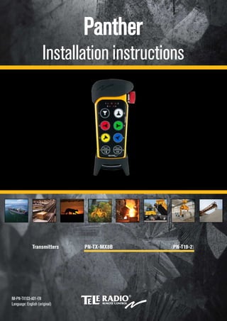
  • 1. Panther Installation instructions                            Transmitters PN-TX-MX8B (PN-T19-2)       IM-PN-TX103-A01-EN Language: English (original)
  • 2. CONTENTS Chapter 1: CUSTOMER INFORMATION 3 Chapter 2: FUNCTIONAL SAFETY 5 Chapter 3: PRODUCT DESCRIPTION 7 Transmitter front 7 Transmitter back 7 Technical data 8 Frequency band 8 Chapter 4: INSTALLERS GUIDE 9 Start the transmitter 9 Switch the transmitter off 9 Logout 9 Register the transmitter in the receiver 10 Erase all transmitters from the receiver 11 Replace 11 Automatic shutdown 12 Show channel 13 Switch channel 13 Load select mode 14 Radio mode 17 Enter menu mode 18 Chapter 5: BATTERY GUIDE 19 Chapter 6: GUARANTEE, SERVICE, REPAIRS AND MAINTENANCE 21 Chapter 7: REGULATORY INFORMATION 22 Chapter 8: FREQUENT TERMS 24
  • 3. Chapter 1: CUSTOMER INFORMATION CHAPTER 1: CUSTOMER INFORMATION   THANK YOU FOR PURCHASING A TELE RADIO AB PRODUCT   READ ALL INSTRUCTIONS AND WARNINGS CAREFULLY BEFORE MOUNTING, INSTALLING AND CONFIGURATING THE PRODUCTS.   These instructions are published by Tele Radio AB and are not subject to any guarantee. The instructions may be removed or revised by Tele Radio AB at any time and without further notice. Corrections and additions will be added to the latest version of the instructions.   IMPORTANT! These instructions are directed to installers. The instructions containing information about the installation and configuration of the radio remote control unit on the machine are not intended to be passed on to the end user. Only information that is needed to operate the machine correctly by radio remote control may be passed on to the end user.   Tele Radio AB products are covered by a guarantee/warranty against material, construction or manufacturing faults. During the guarantee/warranty period, Tele Radio AB may replace the product or faulty parts. Work under guarantee/warranty must be carried out by Tele Radio AB or by an authorized service center specified by Tele Radio AB. Contact your Tele Radio AB representative if you need support or service.   ©Tele Radio AB Datavägen 21 SE-436 32 ASKIM SWEDEN Tel: +46-31-748 54 60 Fax: +46-31-68 54 64 www.tele-radio.com - 3 -
  • 4. WARNINGS & RESTRICTIONS   WARNING! Tele Radio AB remote controls are often built into wider applications. We recommend that the system is equipped with a wired emergency stop where necessary.   NOTE! We recommend that the functionality of the stop button is tested on a regular basis (at least after every 200 hours' use). Test the stop button by pressing it and pulling it out.   INSTALLING, CONNECTING AND MOUNTING  n Only permit licensed or qualified personnel to install the product.  n Switch off the power supply to the receiver before connecting the equipment.  n Check that the power supply is connected to the correct connection terminal.  n To utilize the safety of the system, use the stop relays in the safety circuitry of the object that you want to control.  n Do not use damaged cables. Cables must not hang loose.  n Avoid installing in areas affected by strong vibrations.  n Place the receiver well away from wind, damp and moisture.  n Cable glands and vent plugs must face downwards to prevent water from gaining access.   THE USER  n Only permit qualified personnel to access the transmitter and operate the equipment.  n Make sure that the user follows the instructions.  n Make sure that the user satisfies the age requirements in your country for operating the equip- ment.  n Make sure that the user is not under the influence of drugs, alcohol or medications.  n Make sure that the user does not leave the transmitter unsupervised.  n Make sure that the user always switches the transmitter off when it is not in use.  n Make sure that the user has a clear view of the work area at all times.   MAINTENANCE  n Use the stop button to start and switch off the transmitter as often as possible.  n If error messages are shown, it is very important to find out what caused them.  n If the stop button is mechanically damaged, contact your representative for service immediately.  n Always contact your representative for service and maintenance work on the product.  n Write down the serial numbers/ID codes of the receivers and transmitters used. This information should be recorded in the “Settings document” for your product (download from our website).  n Avoid registering transmitters in receivers where they are not being used.  n Keep the safety instructions for future reference. Always download the configuration instruc- tions from our website for the latest available version.   WEEE DIRECTIVE   This symbol means that inoperative electrical and electronic products must not be mixed with household waste. The European Union has implemented a collection and recycling system for which producers are responsible. For proper treatment, recovery and recycling, please take this product to a designated collection point.   Tele Radio AB strives to minimize the use of hazardous materials, promotes reuse and recycling, and reduces emissions to air, soil and water. When a commercially viable alternative is available, Tele Radio AB strives to restrict or eliminate substances and materials that pose an environmental, health or safety risk. - 4 -
  • 5. Chapter 2: FUNCTIONAL SAFETY CHAPTER 2: FUNCTIONAL SAFETY   NOTE! The information in this section applies only to the products specified below.   Safety function The safety-related stop function in the radio system complies with EN 13849-1:2008 Category 3 PLd. The stop relays on the receiver unit are controlled by the stop button on the transmitter unit. When the stop button is pressed, the stop relays break the power to the safety-related application. The complete end-user system, including the radio system, enters a safe state. The maximum response time for the safety-related stop function is 500ms.   Applicable products The following transmitter and receiver units are designed to comply with the appointed safety requirements: Receivers: PN-R15-1, PN-R15-2, PN-R15-7, PN-R15-8 Transmitter: PN-T19-2   NOTE! Both the receiver and the transmitter used in the specific end-user system must be compliant.   Installation The stop relays on the receiver unit must be correctly installed on the end-user system, to ensure that opened/deactivated stop relays interrupt the power to the safety-related application. The safety level of the stop function can only be credited when used in a complete end-user system that complies with EN 13849-1:2008 Category 3 PLd.   Configuration The default configuration of the receiver unit complies with the appointed safety requirements. Any reconfiguration that breaches the safety requirements will be indicated by a LED on the main board of the receiver unit. Before commissioning the radio system, the installer must check the LED indication.   Function LED Status Indicates PLd status LED (red) ON Not compliant with PLd OFF Compliant with PLd   R1 R2R5R5R5 R4R31 2 R5 1. Stop relays 2. PLd status LED         - 5 -
  • 6. Chapter 2: FUNCTIONAL SAFETY WARNING! All safety-related parameters must be configured as follows in order to comply with the appointed safety requirements:    n The system must be configured in continuous radio mode  n All relays must be switched off when the radio link is down  n The radio link timeout must be set to a maximum of 500ms  n The login/logout function must be activated  n The Custom ID setting must be deactivated, i.e. the receiver must always use the unique trans- mitter ID code - 6 -
  • 7. Chapter 3: PRODUCT DESCRIPTION CHAPTER 3: PRODUCT DESCRIPTION   TRANSMITTER FRONT   1 2 3 4 11 6 5 7 13 12 14 8 9 10 15  1. Rubber cover  2. Stop button  3. LED 2 (red)  4. LED 4 (red)  5. LED 1 (red)  6. LED 3 (red)  7. Top LED (red, green)  8. Button 1  9. Button 3  10. Button 5  11. Button 7 – left start button  12. Button 2  13. Button 4  14. Button 6  15. Button 8 – right start button   TRANSMITTER BACK   1 3 4 5 2  1. Rubber cover  2. Replace ID label (placed under rubber cover)  3. Stop button  4. Battery pack  5. Product label (placed under battery pack) - 7 -
  • 8. TECHNICAL DATA   Number of buttons 8 x 2-step buttons Battery 3 x 1.5V AAA / LR03 in battery pack D4-3 On/off switch No Radio communication Simplex Dimensions 85 x 193 x 43 mm / 3.4 x 7.7 x 1.7 in Weight 300 g / 0.7 lbs Frequency band 2405–2480 MHz Number of channels 16 (channel 11–26) Operating time (continuous usage) Approximately 100 h. with alkaline (depending on settings) IP code 65 Operating temperature -20 – +55 °C / -4 – +130 °F   FREQUENCY BAND   Channel Frequency 11 2405 MHz 12 2410 MHz 13 2415 MHz 14 2420 MHz 15 2425 MHz 16 2430 MHz 17 2435 MHz 18 2440 MHz 19 2445 MHz 20 2450 MHz 21 2455 MHz 22 2460 MHz 23 2465 MHz 24 2470 MHz 25 2475 MHz 26 2480 MHz - 8 -
  • 9. Chapter 4: INSTALLERS GUIDE CHAPTER 4: INSTALLERS GUIDE   START THE TRANSMITTER    1. Make sure that the stop button is pressed.  2. Twist and pull out the stop button. The top LED lights (green when the battery capacity is good, red when the battery capacity is poor), LEDs 3 and 4 flash (red).  3. Press buttons 7 and 8 at the same time for at least 1 second. LEDs 3 and 4 light (red).  4. Release buttons 7 and 8. LEDs 3 and 4 go out. The top LED flashes (green).   SWITCH THE TRANSMITTER OFF    1. Press the stop button.   NOTE! When the transmitter is active and the stop button is pressed, all relays go off.   LOGOUT   WARNING! For the logout function to work, BOTH the receiver and the transmitter must have the logout function activated and be set to continuous radio mode.   NOTE! You cannot activate/deactivate the logout function in the transmitter or the receiver. Contact your representative for assistance.   For this transmitter the logout function is activated by default.   Quick logout   NOTE! Quick logout can only be performed when the transmitter is on and the radio link is up.    1. Press button 7. Keep pressed.  2. Press the stop button. The top LED lights (red). The transmitter takes approximately 3 seconds to logout. The transmitter switches off.   Logout from receiver   This logout option is used when a lost or damaged transmitter must be logged out from the receiver.    1. Press the receiver Select button. LED 10 lights (orange).  2. Keep pressed (for more than 4 seconds). LED 10 goes off. The transmitter is now logged off. Any other registered transmitter can log in. - 9 -
  • 10. Logout from menu mode   This logout option is mainly used when the button for quick logout is used by another function.    1. Make sure that the stop button is pressed.  2. Press button 8. Keep pressed.  3. Twist and pull out the stop button.  4. Release button 8. The top LED flashes (green).  5. WITHIN 1 MINUTE OF PULLING OUT THE STOP BUTTON: Enter the code: 1-2-3-4 (press buttons 1, 2, 3, 4). LEDs 1–4 light up (red). If the code is invalid, the transmitter switches off. When the code is accepted, the top LED flashes (green). LEDs 1–4 flash (red).  6. WITHIN 1 MINUTE OF ENTERING THE CODE: Press button 7. The top LED flashes (red). The transmitter takes approximately 10 seconds to logout. The transmitter switches off.   REGISTER THE TRANSMITTER IN THE RECEIVER   WARNING! Only keep the transmitters that you intend to use registered in the receivers.   NOTE! To establish a radio link between the transmitter and the receiver, both units must be set to the same radio mode.    1. Make sure that the stop button is pressed.  2. Twist and pull out the stop button. The top LED lights (green when the battery capacity is good, red when the battery capacity is poor), LEDs 3 and 4 flash (red).  3. Press buttons 7 and 8 at the same time for at least 1 second. LEDs 3 and 4 light (red).  4. Release buttons 7 and 8. LEDs 3 and 4 go out. The top LED flashes (green).  5. Press the receiver Function button. The function LED lights (red).  6. Press the receiver Select button. All relay LEDs light (red).  7. Press buttons 1 and 2. Keep pressed. All relay LEDs light (red). All relay LEDs flash 2 times (red).   - 10 -
  • 11.  8. Release buttons 1 and 2. All relay LEDs flash 1 time (red). The transmitter is registered.   If no transmitter is found within approximately 10 seconds, the receiver exits to normal operation.   ERASE ALL TRANSMITTERS FROM THE RECEIVER    1. Press the receiver Function button. The function LED lights (red).  2. Press the receiver Select button. Keep pressed (at least 4 seconds). All relay LEDs light (red). All relay LEDs go out.  3. Release the receiver Select button. All transmitters are erased from the receiver.   If the function LED flashes (red), one or more transmitters are still registered in the receiver.   REPLACE   It is possible to replace a registered transmitter with another transmitter without having access to the receiver. Use the new transmitter that is replacing the old transmitter.    1. Make sure that the stop button is pressed.  2. Press button 8. Keep pressed.  3. Twist and pull out the stop button.  4. Release button 8. The top LED flashes (green).  5. WITHIN 1 MINUTE OF PULLING OUT THE STOP BUTTON: Enter the code: 1-2-3-4 (press buttons 1, 2, 3, 4). LEDs 1–4 light up (red). If the code is invalid, the transmitter switches off. When the code is accepted, the top LED flashes (green). LEDs 1–4 flash (red).  6. WITHIN 1 MINUTE OF ENTERING THE CODE: Press button 3. The top LED lights (green). LED 2 flashes (red).  7. Enter the Replace ID (a maximum of 11 digits) for the transmitter being replaced by pressing the transmitter buttons. LED 3 lights (red) when one or more digits have been entered. LEDs 3 and 4 light (red) when the maximum number of digits (11) have been entered.   (000000) Replace ID: 000000000 IMPORTANT! When entering the last digit in the code, keep that button pressed until the stop button has been pressed. IMPORTANT! The Replace ID label is placed in the back of the transmitter. Remove the rubber cover. - 11 -
  • 12.  8. Press the stop button. Release the last Replace ID button. After approximately 10 seconds the transmitter switches off.     If the replace procedure fails, press the stop button and start again.   AUTOMATIC SHUTDOWN   NOTE! Only for continuous radio mode.   Automatic shutdown can save battery capacity by automatically switching the transmitter off following a preset period of inactivity.   Setting the automatic shutdown time    1. Make sure that the stop button is pressed.  2. Press button 8. Keep pressed.  3. Twist and pull out the stop button.  4. Release button 8. The top LED flashes (green).  5. WITHIN 1 MINUTE OF PULLING OUT THE STOP BUTTON: Enter the code: 1-2-3-4 (press buttons 1, 2, 3, 4). LEDs 1–4 light up (red). If the code is invalid, the transmitter switches off. When the code is accepted, the top LED flashes (green). LEDs 1–4 flash (red).  6. WITHIN 1 MINUTE OF ENTERING THE CODE: Press button 5. The top LED lights (green). LED 2 flashes (red).  7. Select the automatic shutdown time by pressing a button according to the following table. The top LED flashes 3 times (green). The transmitter switches off.   Press... Automatic shutdown time after... button 1 3 minutes button 2 6 minutes button 3 12 minutes button 7 No automatic shutdown - 12 -
  • 13. SHOW CHANNEL    1. Make sure that the stop button is pressed.  2. Press button 8. Keep pressed.  3. Twist and pull out the stop button.  4. Release button 8. The top LED flashes (green).  5. WITHIN 1 MINUTE OF PULLING OUT THE STOP BUTTON: Enter the code: 1-2-3-4 (press buttons 1, 2, 3, 4). LEDs 1–4 light up (red). If the code is invalid, the transmitter switches off. When the code is accepted, the top LED flashes (green). LEDs 1–4 flash (red).  6. WITHIN 1 MINUTE OF ENTERING THE CODE: Press button 4. The top LED lights (green).  7. The selected channel will be indicated as follows: LED 1 flashes (red) the number of times corresponding to the first digit. LED 2 flashes (red) the number of times corresponding to the second digit. For example channel 23: LED 1 will flash 2 times, LED 2 will flash 3 times.   SWITCH CHANNEL    1. Make sure that the stop button is pressed.  2. Press button 8. Keep pressed.  3. Twist and pull out the stop button.  4. Release button 8. The top LED flashes (green).  5. WITHIN 1 MINUTE OF PULLING OUT THE STOP BUTTON: Enter the code: 1-2-3-4 (press buttons 1, 2, 3, 4). LEDs 1–4 light up (red). If the code is invalid, the transmitter switches off. When the code is accepted, the top LED flashes (green). LEDs 1–4 flash (red).  6. WITHIN 1 MINUTE OF ENTERING THE CODE: Press button 8. Keep pressed.  7. Press button 4. Release.  8. Release button 8. The top LED lights (green). LED 2 (red) flashes.  9. Select channel 11–26 according to the following table. LED 3 lights (red) when a valid digit has been entered. LEDs 3 and 4 light (red) when two valid digits have been entered. The top LED flashes (green) 3 times. The transmitter switches off.   - 13 -
  • 14. For example channel 20: Press button 2 for the first digit. For zero, press button 8, keep pressed, press button 4, release button 4, release button 8.   Press... for digit... button 1 1 button 2 2 button 3 3 button 4 4 button 5 5 button 6 6 button 8 (shift) + button 1 7 button 8 (shift) + button 2 8 button 8 (shift) + button 3 9 button 8 (shift) + button 4 0   LOAD SELECT MODE   NOTE! Only for continuous radio mode.    1. Make sure that the stop button is pressed.  2. Press button 8. Keep pressed.  3. Twist and pull out the stop button.  4. Release button 8. The top LED flashes (green).  5. WITHIN 1 MINUTE OF PULLING OUT THE STOP BUTTON: Enter the code: 1-2-3-4 (press buttons 1, 2, 3, 4). LEDs 1–4 light up (red). If the code is invalid, the transmitter switches off. When the code is accepted, the top LED flashes (green). LEDs 1–4 flash (red).  6. WITHIN 1 MINUTE OF ENTERING THE CODE: Press button 6. The top LED lights (green). LED 2 flashes (red).  7. Select a Load select mode by pressing a button according to the following table. The top LED flashes (green) 3 times. The transmitter switches off.   Press... for Load select mode... with this load selected at start-up button 7 0 (default) none button 1 1 A button 2 2 A button 3 3 A button 4 4 A   - 14 -
  • 15. LOAD SELECT MODE 0-4   Load select mode 0 Load select mode 1         Load select mode 2 Load select mode 3       Load select mode 4         - 15 -
  • 16. LOAD AT START-UP   NOTE! Be sure to select Load select mode BEFORE selecting Load at start-up.    1. Make sure that the stop button is pressed.  2. Press button 8. Keep pressed.  3. Twist and pull out the stop button.  4. Release button 8. The top LED flashes (green).  5. WITHIN 1 MINUTE OF PULLING OUT THE STOP BUTTON: Enter the code: 1-2-3-4 (press buttons 1, 2, 3, 4). LEDs 1–4 light up (red). If the code is invalid, the transmitter switches off. When the code is accepted, the top LED flashes (green). LEDs 1–4 flash (red).  6. WITHIN 1 MINUTE OF ENTERING THE CODE: Press button 8. Keep pressed.  7. Press button 6. Release.  8. Release button 8. The top LED lights (green). LED 2 flashes (red).  9. Select Load at start-up by pressing a button according to the following table. The top LED flashes (green) 3 times. The transmitter switches off. Press... for Load at start-up... button 7 none button 1 A button 2 B button 3 A+B - 16 -
  • 17. RADIO MODE   NOTE! To establish a radio link between the transmitter and the receiver, both units must be set to the same radio mode.   This transmitter is set to continuous radio mode by default. The transmitter starts to transmit continuously as soon as it is started. The radio transmission ends when the stop button is pressed. When the system is in continuous radio mode, buttons 7 and 8 are used as start buttons.   Note that some functions are only available when the products are transmitting continuously. Those functions are marked: "Only for continuous radio mode".   To switch radio mode in the receiver, select an Operating mode that supports continuous/ discontinuous radio mode, depending on your preference. To switch radio mode in the transmitter, see "Switch radio mode in transmitter" on the next page.   SWITCH RADIO MODE IN TRANSMITTER   NOTE! Be sure to set the receiver to an Operating mode that supports continuous/discontinuous Radio mode, depending on your preference, before following the instructions below.    1. Make sure that the stop button is pressed.  2. Press button 8. Keep pressed.  3. Twist and pull out the stop button.  4. Release button 8. The top LED flashes (green).  5. WITHIN 1 MINUTE OF PULLING OUT THE STOP BUTTON: Enter the code: 1-2-3-4 (press buttons 1, 2, 3, 4). LEDs 1–4 light up (red). If the code is invalid, the transmitter switches off. When the code is accepted, the top LED flashes (green). LEDs 1–4 flash (red).  6. WITHIN 1 MINUTE OF ENTERING THE CODE: Press button 1. The top LED lights (green). LED 2 flashes (red).  7. Select radio mode by pressing a button according to the following table. The top LED flashes (green) 3 times. The transmitter switches off.   Press... for Radio mode... button 1 continuous (default) button 2 discontinuous - 17 -
  • 18. ENTER MENU MODE    1. Make sure that the stop button is pressed.  2. Press button 8. Keep pressed.  3. Twist and pull out the stop button.  4. Release button 8. The top LED flashes (green).  5. WITHIN 1 MINUTE OF PULLING OUT THE STOP BUTTON: Enter the code: 1-2-3-4 (press buttons 1, 2, 3, 4). LEDs 1–4 light up (red). If the code is invalid, the transmitter switches off. When the code is accepted, the top LED flashes (green). LEDs 1–4 flash (red).  6. WITHIN 1 MINUTE OF ENTERING THE CODE: Enter a menu by pressing the buttons according to the image below.     1 3 5 6 4 2 7  1. Radio mode  2. Replace  3. Show channel  4. Automatic shutdown  5. Load select mode  6. Logout  7. Shift button Shift + 3. Switch channel Shift + 5. Load at start-up - 18 -
  • 19. Chapter 5: BATTERY GUIDE CHAPTER 5: BATTERY GUIDE   NOTE! Electronics and batteries must be physically separated before disposal. Make sure that electronics or batteries are not disposed of in household waste.   NOTE! When approximately 10 % of battery capacity remains, the top LED lights red.   BATTERY INFORMATION   NOTE! Two different battery types – D4-2 and D4-3 – are available for use in the transmitter. The transmitter is supplied with D4-3 batteries.     D4-2 D4-3 Type of battery Replaceable, rechargeable lithium-ion battery Replaceable battery pack with 3 x 1.5V AAA / LR03 batteries Operating time Approximately 150 h. (depending on settings) Approximately 100 h. with alkaline (depending on settings) Charge Charge in the Tele Radio AB charger unit Do not charge in the Tele Radio AB charger unit. Replace the batteries inside the battery pack. Charging temperature 0 – +45 °C / +32 – +113 °F Not applicable   BATTERY PRECAUTIONS   Observe the following general battery warnings:  n As batteries contain flammable substances such as lithium or other organic solvents, they may cause heating, rupture or ignition.  n Risk of explosion if a battery is replaced with the incorrect type of battery.  n Do not short circuit, disassemble, deform or heat batteries.  n Never try to charge a visibly damaged or frozen battery.  n Keep batteries out of reach of small children. If a child swallows a battery, seek immediate med- ical attention.  n Avoid direct soldering to batteries.  n When discarding batteries, insulate the + and - terminals of batteries with insulating/masking tape. Do not put multiple batteries into the same plastic bag.  n When improperly disposed, batteries may short circuit, causing them to become hot, burst or ignite.  n Store in a cool place. Keep batteries away from direct sunlight, high temperatures, and high humidity.  n Do not throw batteries onto fire. - 19 -
  • 20. CHANGE BATTERIES   Change batteries in battery pack D4-3   WARNING! Do not charge battery pack D4-3 in the Tele Radio AB charger unit or in any other charger.    1. Remove the battery pack from the back of the transmitter.  2. Open the battery pack.  3. Replace the 3 x 1.5V AAA / LR03 batteries. Use alkaline batteries for optimal performance.  4. Put the battery pack back in the transmitter. - 20 -
  • 21. Chapter 6: GUARANTEE, SERVICE, REPAIRS AND MAINTENANCE CHAPTER 6: GUARANTEE, SERVICE, REPAIRS AND MAINTENANCE   Tele Radio AB products are covered by a guarantee/warranty against material, construction and manufacturing faults. During the guarantee/warranty period, Tele Radio AB may replace the product or faulty parts. Work under guarantee/warranty must be carried out by Tele Radio AB or by an authorized service centre specified by Tele Radio AB.   The following are not covered by the guarantee/warranty:  n Faults resulting from normal wear and tear  n Parts of a consumable nature  n Products that have been subject to unauthorized modifications  n Faults resulting from incorrect installation and use  n Damp and water damage   Maintenance:  n Repairs and maintenance must be carried out by qualified personnel  n Use spare parts from Tele Radio AB only  n Contact your representative if you require service or other assistance  n Keep the product in a dry, clean place  n Keep contacts and antennas clean  n Wipe off dust using a slightly damp, clean cloth   WARNING! Never use cleaning solutions or high-pressure water. - 21 -
  • 22. Chapter 7: REGULATORY INFORMATION CHAPTER 7: REGULATORY INFORMATION   CE MARKING   This product is in compliance with the essential requirements of directive 1995/5/EC of the European Parliament and of the Council. Latest version of the Declaration of Conformity can be downloaded from the Tele Radio AB website.   FCC STATEMENT   This device complies with part 15 of the FCC Rules. Operation is subject to the following two conditions: (1) This device may not cause harmful interference, and (2) this device must accept any interference received, including interference that may cause undesired operation.   Changes or modifications not expressly approved by the party responsible for compliance could void the user’s authority to operate the equipment.   This equipment has been tested and found to comply with the limits for a Class B digital device, pursuant to part 15 of the FCC Rules. These limits are designed to provide reasonable protection against harmful interference in a residential installation. This equipment generates uses and can radiate radio frequency energy and, if not installed and used in accordance with the instructions, may cause harmful interference to radio communications. However there is no guarantee that interference will not occur in a particular installation. If this equipment does cause harmful interference to radio or television reception, which can be determined by turning the equipment off and on, the user is encouraged to try to correct the interference by one or more of the following measures:   –Reorient or relocate the receiving antenna. –Increase the separation between the equipment and receiver. –Connect the equipment into an outlet on a circuit different from that to which the receiver is connected. –Consult the dealer or an experienced radio/TV technician for help.   To satisfy FCC RF exposure requirements, a separation distance of 20 cm or more should be maintained between the antenna of this device and persons during device operation. To ensure compliance, operations at closer than this distance is not recommended.   IC STATEMENT   This product complies with Industry Canada's licence-exempt RSSs. Operation is subject to the following two conditions: (1) This device may not cause interference; and (2) This device must accept any interference, including interference that may cause undesired operation of device.   Le présent appareil est conforme aux CNR d'Industrie Canada applicables aux appareils radio exempts de licence. L'exploitationest autorisée aux deux conditions suivantes : (1) l'appareil ne doit pas produire de brouillage, et (2) l'utilisateur de l'appareil doit accepter tout brouillage radioélectrique subi, même si le brouillage est susceptible d'en compromettre le fonctionnement.   To satisfy IC RF exposure requirements, a separation distance of 20 cm or more should be maintained between the antenna of this device and persons during device operation. To ensure compliance, operations at closer than this distance is not recommended.   - 22 -
  • 23. Chapter 7: REGULATORY INFORMATION Les antennes installées doivent être situées de facon à ce que la population ne puisse y être exposée à une distance de moin de 20 cm. Installer les antennes de facon à ce que le personnel ne puisse approcher à 20 cm ou moins de la position centrale de l'antenne. La FCC des éltats-unis stipule que cet appareil doit être en tout temps éloigné d'au moins 20 cm personnes pendant son functionnement. - 23 -
  • 24. Chapter 8: FREQUENT TERMS CHAPTER 8: FREQUENT TERMS   Configuration ID Numerical code stored in both the transmitter and receiver unit. The receiver unit can only be controlled by a transmitter with the correct configuration ID.     Continuous radio mode When in continuous radio mode the transmitter unit transmits continuously when it is switched on.     Custom ID Numerical code stored in the transmitter unit, used to replace the unique ID code. One or several transmitter units can be configured with the same custom ID and the receiver will recognise them all as the same transmitter unit.     Discontinuous radio mode When in discontinuous radio mode the transmitter unit transmits whenever it is switched on and a button is pressed. The transmission is interrupted when all but- tons are released.     Function relay Standard relay, controlled by the buttons on the transmitter unit.     Interlocking Prevents a component from functioning when another component is functioning or operating in a particular way.     Latching relay functionality The relay becomes active every time you press a button and remains active until the button is pressed again.     Load select mode One or more Load select modes are stored in the transmitter unit. Activating a spe- cific Load select mode results in a group of preselected relays on the receiver unit, which may be controlled from the transmitter unit.     Momentary relay functionality The relay will only be active while a button is pressed on the transmitter. When the button is released, the relay will no longer be active.     On relay Relay that is active when the receiver unit is operating and a radio link is established, regardless of whether any other relays are active.     Operating mode One or more operating modes are stored in the receiver unit. Each operating mode describes which relays on the receiver unit are controlled when specific buttons on the transmitter unit are pressed.     Replace ID Numerical code used to identify the transmitter during the Replace procedure.     Stop relay Safety related relay controlled by the stop button on the receiver. Intended to inter- rupt the power supply to a safety application controlled by the receiver unit.     Work relay Relay that is active when any other specified relay(s) on the receiver unit is/are act- ive.     Zero position check Security function ensuring that potentially active buttons/joysticks upon start up or lost/found radio links must be in the zero position before the system can be used to avoid unplanned movements of the controlled object. - 24 -
  • 25.                         (This page has intentionally been left blank)                                                                         - 25 -
  • 26. This installation instruction is subject to change without prior notice. Download the latest installation instruction from www.tele-radio.com