SlideShare a Scribd company logo
1 of 56
Download to read offline
upload_0001.wmv design.wmv gallery.wmv
PROJECT DEGINE BY:
VYAS TAJAGNA
MANUFACTURED BY:
PATEL JAIMIN
PRAJAPATI MEHUL
ASSEMBLED BY:
DHOLARIA DHARMESH
GHAJERA CHINTAN
GHAJERA TUSHAR
THE THIRD EYE
REMOTE CONTROLLED HOVERCRAFT
A PROJECT REPORT
Submitted in partial fulfillment of the requirements for the award of the certificate
Of
DIPLOMA
IN
MECHANICAL ENGINEERING
BY
VYAS TAJAGNA PARTHESHKUMAR 106750319015
PATEL JAIMIN BHARATBHAI 106750319002
PRAJAPATI MEHUL RAMESHBHAI 106750319034
GAJERA CHINTAN PARSHOTTAMBHAI 106750319030
GAJERA TUSHAR JAYSUKHBHAI 106750319018
DHOLARIA DHRMESH LAXMANBHAI 106750319023
UNDER THE GUIDENCE OF
MR R.P.PRAJAPATI
MR D.M.RASAMIYA
MR N.K.TRIPATHI
MR.HARDIP PANDYA
MR.NILESH DOSHI
DEPARTMENT OF MECHANICAL ENGINEERING
F.D.(MUBIN) INSTITUTE OF ENGINEERING AND TECHNOLOGY,DAHEGAM
PIN-382308, GANDHINAGAR, GUJARAT, INDIA
CERTIFICATE
This is to certify that,
Mr. VYAS TAJAGNA PARTHESHKUMAR
From F.D.( MUBIN) Institute of engineering & Technology college
having Enrollment no.106750319015 has completed Report on the
Semester –VI Project Report having title Remote Control Hovercraft.
In a group consisting of 6 persons under the guidance of the
Mr.NileshTripathi , Mr.DipakRasamiya and Mr.RakeshPrajapati.
Institute Guide- UDP Head of Department
DATE
The purpose of our project is to construct a functioning hovercraft designed through fundamental
principles. Through this design project, we explore the process of engineering from initial design to
product construction. We were forced plan around material limitations and me constraints. We
produced a vehicle capable of hovering and forward motion.
Hovercrafts are multi-purpose vehicles which can travel across various types of terrain with no
alteration. The overall purpose for this design project is to build a hovercraft which can carry various
payloads, across land and water. This air cushioned vehicle (ACV) can be used for numerous different
applications including military, aid, transportation of building supplies, etc. This report will outline the
design process as well as the final selected design. It also includes sections on fabrication and testing of
the hovercraft and all its components. Also included in this report are detailed design drawings, detailed
budget, a list of calculations done for the project.
We place on record and warmly acknowledge the continuous encouragement, invaluable supervision,
timely suggestions and inspired guidance offered by our guide MR. RAKESH PRAJAPATI, Professor,
Department of Mechanical Engineering, in bringing this project to a successful completion.
We are grateful to MR. DEEPAK RASAMIYA, Head of the Department of Mechanical engineering, for
permitting us to make use of the facilities available in the department to carry out the project
successfully. Last but not the least we express our sincere thanks to all of our friends who have
patiently extended all sorts of help for accomplishing this undertaking.
We are thankful to MR. NILESH TRIPATHI and MR. LALBHAI THAKORE for their support for electric
equipment’s and also thanks to MR. HARDIP PANDYA for technical advice.
We are thankful to MR. NILESH DOSHI for guiding us in purchasing equipment’s and also thankful to
MR. SHAILESH AMIN, MR. KAMLESH PATEL, MR. KALPESH NAI.
Finally we express our gratefulness to those who are directly or indirectly responsible for successful
completion of this project.
I). ABSTRACT……………………………………………………………………………………..………………………………………………………………...I
II). ACKNOWLEDGMENT……………………………………………………………………………………………………………………………………….II
III). TABLE OF CONTENTS……………………………………………………………………………………………………………………………………..III
IV). LIST OF FIGURES……………………………………………………………………………..…………………………………………………………….IV
V). LIST OF TABLES………………………………………………………………………………………………………………………………………………..V
VI). NOMECLATURE
1). ACRONYMS………………………………………………………………………………………………………………………………………………VI
2). LIST OF SYMBOLS……………………………………………………………………………………………………………………………........VII
1 HISTORY…………….…………………………………………………………………………………………………………………………………………..002
2 ABOUT PROJECT
2.1 INTRODUCTION…………………………………………………………………………………………………………………………………….004
2.2 OBJECTIVE…………………………………………………………………………………………………………………………………………….005
3 SELECTION OF EQUIPMENT
3.1 PROPULSION EQUIPMENT..…………………………………………………………………………………………………………………..007
3.2 LIFT EQUIPMENT…………………………………………………………………………………………………………………………………..008
3.3 BODY MATERIAL…….…………………………………………………………………………………………………………………………….009
3.4 SKIRT MATERIAL….……………………………………………………………………………………………………………………………….009
3.5 POWER SOURCE….……………………………………………………………………………………………………………………………….010
3.6 BODY DESIGN……………………………………………………………………………………………………………………………………….010
4 DETAIL DESIGN
4.1 LIFT…………………………………………………………………….……………………….……………………………………………………….012
4.2 PROPULSION……………………………………………………………………………….……………………………………………………….014
4.3 PLATFORM & SKIRT……………………………………………………………………..……………………………………………………….016
5 MANUFACTURING…..……………………………………………………………………………..……………………………………………………..019
6 CONTROLLING……………………………………………………………………………………………………………………………..………………..023
7 TESTING………………………………………………………………………………………………………….……………………………………………..026
8 CONCLUSION AND REFERANCES
8.1 CONCLUSION………………………………………………………………………………………………………………………………………..030
8.2 REFERANCES………………………………………………………………………………………….……………………………………………..030
VII) BILL OF MATERIAL………………………………………………………………………………………………….…………………………………..VIII
VIII) PROJECT SCHEDULE………………………………………………………………………………………………………………………………………X
IX) CPM AND PERT ANALYSIS…………………………………………………………………………………………………………………………….XI
X) BUDGET………………………………………………………………………………………………………………………………………….……………XII
XI) CALCULATION………….……………………………………………………………………………………………..……………………….…………XIII
XII) DESIGN……………………….……………………………………………………………………………………………………..………….…………..XIV
XIII) MOMENTS AT WORK……………………………………….……………………………………………………………………………………….XXII
1 HOVERCRAFT PRINCIPAL DESIGN………….…………………………………………………………………………………………………..…..004
2 SELECTED PROPELLER ………………………………………………………………………………………………………………………….………..012
3 LIFT MOUNTING DESIGN ……………………………………………………………………………………………………………………..………..013
4 SELECTED MOTOR …………………………………………………………………………………………………………………………………………014
5 MOTOR SUPPORT ………………………………………………………………………………………………………………………………………….015
6 FAN DUCT ……………………………………………………………………………………………………………………………………………..………016
7 PLATFORM DESIGN …………………………………………………………………………………………………………………………………......017
8 SKIRT DESIGN ………………………………………………………………………………………………………………………………………….......018
9 PLATFORM CONSTRUCTION ……………………………………………………………………………………………………………………......020
10 LIFT MOUNTING CONSTRUCTION………………………………………………………………………………………………………………..020
11FAN DUCT CONSTRUCTION……………………………………………………………………………………………………………..…………..020
12 MOTOR SUPPORT……………………………………………………………………………………………………………………………….……….021
13 SKIRT CONSTRUCTION…………………………………………………………………………………………………………………………..…….021
14 ASSEMBLY……..…………………………………………………………………………………………………………………………………………….021
15 FINAL CONSTRUCTION…………………………………………………………………………………………………………………………………022
16CIRCUIT DESIGN……………………………………………………………………………………………………………………………………….....024
17REMOTE AND RECIEVER……………………………………………………………………………………………………………………………….024
18 BATTERY………………………………………………………………………………………………………………………………………………………025
19 MOTOR………………………………………………………………………………………………………………………………………………………..025
20 SERVOMOTOR……………………………………………………………………………………………………………………………………………..025
1 PROPULSION EQUIPMENT SELECTION MATRIX.……………………………………………………………………………………………..007
2 LIFT EQUIPMENT SELECTION MATRIX…..………………………………………………………………………………………………………..008
3 BODY MATERIAL SELECTION MATRIX……………………………………………………………………………………………………………..009
4 SKIRT MATERIAL SELECTION MATRIX……………………………………………………………………………………………………………..009
5 POWER SOURCE SELECTION MATRIX……………………………………………………………………………………………………………..010
6 BODY DESIGN SELECTION MATRIX…..…………………………………………………………………………………………………………….010
7 TERRAIN TESTING RESULT……………………………………………………………………………………………………………………………..028
8 BILL OF MATERIAL………………………………………………………………………………………………………………………………………….VIII
9 PROJECT SCHEDULE…………………………………………………………………………………………………………………………………………..X
10 CRITICAL PATH METHOD ANALYSIS………………………………………………………………………………………………………………..XI
11 BUDGET…………………………………………………………………………………………………………………………………………………………XII
1).ACRONYMS
 ACV = AIR CUSHION VEHICAL
 UFO = UNDENTIFIED FLYING OBJECT
 ESC = ELECTRONIC SPEED CONTROLLER
 BOM = BILL OF MATERIAL
 LI-PO= LITHIUM POLYMER
 CPM = CRITICAL PATH METHOD
 BEC = BATTERY ELLIMINATOR CIRCUIT
There have been many attempts to understand the principles of high air pressure below hulls and
wings. To a great extent, the majority of these can be termed "ground effect" or "water effect" vehicles
rather than hovercraft. The principal difference is that a hovercraft can lift itself while still, whereas the
majority of other designs require forward motion to create lift. These active-motion "surface effect
vehicles" are known in specific cases as ekranoplan and hydrofoils.
The first mention in the historical record of the concepts behind surface-effect vehicles that used the
term hovering was by Swedish scientist Emanuel Swedenborg in 1716 In 1915, Austrian Dagobert Müller
(1880 - 1956) built the world's first "water effect" vehicle. Shaped like a section of a large aero foil (this
creates a low pressure area above the wing much like an aircraft), the craft was propelled by four aero
engines driving two submerged marine propellers, with a fifth engine that blew air under the front of
the craft to increase the air pressure under it. Only when in motion could the craft trap air under the
front, increasing lift. The vessel also required a depth of water to operate and could not transition to
land or other surfaces. Designed as a fast torpedo boat, the Versuchsgleitboot had a top speed over 32
knots (59 km/h). It was thoroughly tested and even armed with torpedoes and machine guns for
operation in the Adriatic. It never saw actual combat, however, and as the war progressed it was
eventually scrapped due to lack of interest and perceived need, and its engines returned to the Air
Force.
In 1931, Finnish aero engineer Toivo J. Kaario began designing a developed version of a vessel using an
air cushion and built a prototype Pintaliitäjä (Surface Soarer), in 1937.[4] Kaario's design included the
modern features of a lift engine blowing air into a flexible envelope for lift. Kaario never received
funding to build his design, however.[citation needed] Kaario's efforts were followed closely in the
Soviet Union by Vladimir Levkov, who returned to the solid-sided design of the Versuchsgleitboot.
Levkov designed and built a number of similar craft during the 1930s, and his L-5 fast-attack boat
reached 70 kn (130 km/h) in testing. However, the start of World War II put an end to Levkov's
development work.
During World War II, an engineer in the United States of America, Charles Fletcher, invented a walled
air cushion vehicle. Because the project was classified by the U.S. government, Fletcher could not file a
patent.
A hovercraft is a vehicle capable of traveling over most surfaces on a cushion of air trapped under the
body for lift. Air propellers, water propellers, or water jets usually provide forward propulsion. Air-
cushion vehicles can attain higher speeds than can either ships or most land vehicles due to lower
frictional forces and use much less power than helicopters of the same weight. Figure 1 above illustrates
the operational principles and basic components of a typical hovercraft.
Specifically for our hovercraft, there are three main design groups: the lift, thrust, and steering
systems. The arrangement of the hovercraft is similar to that shown in Figure 1. The propeller shown
must be designed for a vehicle as typical fans act by creating vortices to mix the air, reducing the
ejected air’s translational kinetic energy and significantly reducing efficiency. We outline key features of
the three main groups below.
Lift System
The hovercraft relies on a stable cushion of air to maintain sufficient lift. The air ejected from the
propeller is separated by a horizontal divider into pressurized air utilized for the aircushion and
momentum used for thrust. The weight distribution on top of the deck is arranged so that the air is
distributed the air from the rear of the deck throughout the cushion volume in an approximately even
fashion to provide the necessary support. The skirt extending below the deck provides containment,
Figure 1 HOVER CRAFT PRINCIPAL DESIGN
improves balance, and allows the craft to traverse more varied terrain. We maintain the rigidity of the
skirt by filling the air-tight skirt with the same pressurized air diverted towards lift.
Thrust System
The air not directed to the cushion and skirt is propelled backwards, providing forward thrust to the
craft. The size of the propeller, rpm output of the engine, and height of the lift/thrust divider are the
determining parameters for the thrust force. A thrust duct channeling the air into the propeller can
provide up to a 15% increase in efficiency [Universal Hovercraft]. The limiting factor for the thrust is the
air flow available to direct backwards since our primary concern is providing pressurized air for air
cushion and lift. As a result, our forward speed is limited but maintainable.
Steering System
Since a hovercraft lacks the same frictional and drag effects as boats or cars, steering must be
approached without precise control in mind. This is especially true in our case as the power supply is
limited. Rudders are a main source of steering and are attached to the rear of the duct to direct the flow
of air and the direction of the subsequent momentum transfer from the air to the craft. The driver
controls the movement of the rudders through a joystick located in the front of the craft. A throttle on
the engine situated next to the driver allows him to vary the speed of the craft, allowing for a smaller
radius of turning once proper driving techniques are mastered. Because of the air cushion effect, the
driver may influence the steering by shifting his weight nearer to any of the four sides of the deck. For
example, a shift right turns the hovercraft to the right. In the remainder of the report, we discuss our
design and construction processes, the results from testing the craft, the problems associated to our
design and construction, and possible improvements.
Our goal is to present a clear description of hovercraft history, design concepts, and fundamentals, and
to incorporate these into a well thought out design to be considered for manufacturing. We expect that
our hovercraft will successfully complete the course, will achieve maximum top speed with minimal
cost, will be aesthetically pleasing to the client and spectators, will be reliable and durable for use in
multiple runs and will be safe for all concerned.
Once our list of concepts was completed we created a screening matrix from them. The matrix was
used to evaluate each concept against each client need. The evaluation system we employed was: for
each concept and client need a −, 0 or + was assigned to indicate a negative response, a neutral
response and a positive response respectively. This evaluation was done by each team member
individually. Once the individual screening was completed, we assembled as a team to compare our
results, and form a master screening matrix, with which are all in agreement - this is what is presented
beginning on the following tables.
TABLE 1 : PROPULSION EQUIPMENT SELECTION MATRIX
Equipment
safe
durable
Lightweight
Easytomanufacture
Easytodesign
portable
Costeffective
Marketavailability
THRUST POWER
Single rocket - - - - - 0 - -
Double rocket - - - - - 0 - -
Single motor + + + + + + + +
Double motor + + + + 0 + + +
Diesel engine 0 + 0 0 0 0 - 0
Petrol engine 0 + 0 0 0 0 - 0
POWER SOURCE
Single fan – single battery + + + + + + + +
Double fan – double battery + + + + 0 + 0 +
FAN TYPE
Turbo fan - 0 - - 0 0 - 0
Propeller – glass - - 0 - - 0 - 0
Propeller – polycarbonate + + + + + + + +
Propeller – wood + + + 0 0 + + +
STEERING SYSTEM
Mounting table - - - - - - - -
Rudder system + + + + + + + +
TABLE 2 : LIFT EQUIPMENT SELECTION MATRIX
Equipment
safe
durable
Lightweight
Easytomanufacture
Easytodesign
portable
Costeffective
Marketavailability
LIFT POWER
Single motor + + + + + + + +
Double motor + + + + + + 0 +
Diesel engine 0 + 0 0 0 0 - 0
Petrol engine 0 + 0 0 0 0 - 0
Leaf blower + + - - - 0 - 0
Vacuum cleaner + + - - - - - +
POWER SOURCE
Single fan – single battery + + + + + + + +
Double fan – double battery + + + + 0 + 0 +
PROPELLER TYPE
Turbo fan - 0 - - 0 0 - 0
Propeller – glass - - 0 - - 0 - 0
Propeller –poly carbonate + + + + + + + +
Propeller – wood + + + 0 0 + + +
TABLE 3 : BODY MATERIAL SELECTION MATRIX
Equipment
safe
durable
Lightweight
Easytomanufacture
Easytodesign
portable
Costeffective
Marketavailability
Carbon fiber + + + - - + - -
Cardboard + - + + + + 0 +
Aluminium + + 0 0 0 + 0 +
Fiberglass + + 0 0 0 + - 0
Glass - 0 0 0 0 + - +
Paper + - + + + + + +
Steel + + - 0 0 + 0 +
Light weight wood + + 0 + 0 + 0 +
Heavy weight wood + + 0 0 0 + 0 +
Plastic + + + + + + 0 +
Sheet metal + + - 0 0 + - +
Waterproof wood + + - 0 0 + - +
Foam + + + + + + + +
TABLE 4 : SKIRT MATERIAL SELECTION MATRIX
Equipment
safe
durable
Lightweight
Easytomanufacture
Easytodesign
portable
Costeffective
Marketavailability
Rubber + 0 + + + + + +
Plastic + + + + + + + +
Paper + - + + + + + +
Cloth + + + + + + 0 +
Neoprene + 0 + 0 + + + 0
Cushion + + + + + + 0 +
Nylon + + + + + + 0 +
Oiled paper + - + + + + + +
polyethylene + + + 0 + + + +
TABLE 5 : POWER SOURCE SELECTION MATRIX
Equipment safe
durable
Lightweight
Easytomanufacture
Easytodesign
portable
Costeffective
Marketavailability
Battery + + + + + + + +
Storage battery + + - 0 0 + - +
Chemical - - + 0 0 - + 0
Solar power + - + 0 0 + - 0
Wind power from lift fan + 0 + 0 0 + - 0
TABLE 6 : BODY DESIGN SELECTION MATRIX
Equipment
safe
durable
Lightweight
Easytomanufacture
Easytodesign
portable
Costeffective
Marketavailability
Easytoassemble
appearance
Ellipse + + + 0 0 + 0 0 - -
Square + + + + + + + + + 0
Rectangle + 0 + + + + + + + 0
Triangle + + + 0 0 + + - + -
Saucer + + + 0 - + 0 0 - 0
Circular (like a UFO) + + + - - + 0 - - 0
Rectangle (rounded
corner)
+ + + + + + + + + +
Aerodynamic + + + - - + - 0 0 +
Life boat + + + + + + + + + +
4.1.1 Design Specifications
The lift system was designed to supply airflow to the air cushion in order to lift the weight of the
hovercraft, including the desired payload, giving a total lifting weight capacity of 100 kilograms to allow
for battery weight and additional mounted devices. The system itself was required to meet a set of
requirements, as detailed below.
 It was to be of light weight, as this was one of the general requirements for all components.
 The system should be small given the special restraints present on the platform.
 The design should be simple, as a complex design would lead to further complications with the
potential to increase the overall size of the system.
4.1.2 Propeller Design
Propellers are best when a low flow rate and high static pressure is required. Given that a high flow rate
and comparatively low static pressure was required in order to achieve lift, an axial flow fan was
selected as the most suitable fan type for this application. A detailed analysis of the variables present in
axial fan design was carried out to determine which characteristics best suited this application. There
are two main parameters in fan design which influence the characteristics of a fan; the blade pitch, and
the number of blades. In general, the rotational speed, diameter, flow rate and static pressure are all
specified prior to selecting a fan.
SELECTED PROPELLER AS PER THE TABLE 1
4.1.3 Mounting structure design
As seen in Figure 3 raising the motor vertically upwards a height of 6 inches gives this design two major
advantages. First it removes the risk of the fan damaging the skirt during deflation, because the skirt
cannot deflate in close proximity to the blades. The main reason for this selection is the ability to funnel
the air flow into a smaller cross section as well as keeping the skirt Fan material out of the vicinity of the
fan blades.
Figure 2 SELECTED PROPELLER
SELECTED MOUNTING FOR LIFTING SYSTEM
Figure 3 LIFT MOUNTING DESIGN
In order to provide cushion, flow of air must be guided properly towards the base. As shown in the
figure 3 the mounting has been kept on the raised platform so that air coming from the outside can be
guided through narrow region to the base.
4.1.4 Motor design
The propulsion motors are used to drive the propellers, providing thrust to accelerate the hovercraft.
The motors required a high degree of controllability, the ability to turn on/off quickly and operate over
a variety of operational speeds. To achieve this an electric motor was required, as no other engine can
achieve the high degree of controllability needed.
Due to the rotational properties of the vectored thrust design, a motor was required with a high
power to weight ratio. Able to provide high power levels, whilst remaining light weight, so not to
restrict the rotation of the propulsion system. Further the motor size must remain small enough not
to restrict the flow into the propeller, in a direct drive configuration. Based on this it was determined
A brushless electric motor was required over a brushed motor, able to provide more power and lower
Electromagnetic interference. Size restrictions further limited selection to an in-runner motor over an
out runner, being significantly smaller, allowing for higher flow and thrust efficiencies.
SELECTED BRUSHLESS MOTOR AS PER THE TABLE 2
Propulsion is defined as the forces required to cause motion over a given terrain. The basic principle
of hovercraft propulsion is momentum theory. Momentum theory in principle, describes motion of the
platform based on a reactive force to the change in momentum of airflow accelerated via a propulsion
system. Using dimensionless coefficients of thrust and power, a propeller and power house have been
selected based on these principles.
4.2.1 Design Specifications
Several design criteria were identified for the propulsion system. The main requirement was the need
to maintain maneuverability of the craft by providing the ability to apply forces in the forward, back and
sideward directions. This ensures sufficient maneuverability to control the hovercraft in accordance
with operational scenarios identified for mine detection regimes. Additional requirements, beyond
providing thrust, include obtaining the highest efficiency system at the lowest weight and power costs.
As the special limitations of the platform are significant this also becomes an important criteria for
selection. The design specifications are summarized below:
 Propulsion systems must be independent of the lift system
 Provide thrust forces to overcome the inertial and drag loadings on the craft
 The platform must have the capacity to DE accelerate to rest in the same time
 Maintain a constant velocity at operational of 5 m/s
Figure 4 SELECTED MOTOR
 Provide thrust forcing in all directions outward of the platform to ensure sufficient maneuver-
ability for autonomy
 Be of high efficiency, and fit within the spatial bounds of the platform
4.2.2 Propeller Design
Propeller which can be used in lift system same like it is used in propulsion system.
4.2.3 Mounting structure design
There were several requirements determined for the design of the propulsion mount. These included
limitlessly rotate the thrust vector 360 degrees, the ability to resist deflection as a result of thrusting,
and simple and easy manufacture and assembly. Furthermore, with safety was an important
consideration due to the rotation of a fast moving propeller. It was to be ensured that the rotation of
the two propulsion mounts could be achieved independently without interference.
The air not directed to the cushion and skirt is propelled backwards, providing forward thrust to the
craft. The size of the propeller, rpm output of the engine, and height of the lift/thrust divider are the
determining parameters for the thrust force. A thrust duct channeling the air into the propeller can
provide up to a 15% increase in efficiency [Universal Hovercraft]. The limiting factor for the thrust is the
air flow available to direct backwards since our primary concern is providing pressurized air for air
cushion and lift. As a result, our forward speed is limited but maintainable.
SELECTED MOUNTING FOR PROPULSION SYSTEM
Propulsion motor has been placed on the base through triangular shaped extruded support as shown in
the figure. In order to introduce steering effect flat panels have been placed just behind the motor. The
panels are movable through servo motor.
Figure 5 MOTOR SUPPORT
4.2.4 Motor design
Motor which can be used in lift system same like it is used in propulsion system.
4.2.5 Fan duct design
Similar to the lifting motor, air flow from propulsion has to be directed through guide walls as shown in
the figure. This panels provide support to the steering panels as well.
SELECTED FAN DUCT DESIGN
4.3.1 Top plate design
The top plates primary function is to house and support all sub systems as well as form the top seal
of the pressure chamber, and hence requires a high level flexural rigidity to avoid undue deflection
with the potential of damaging the lift fan which is mounted within the pressure chamber. Moreover
a high compressive modulus is required to endure repetitive application of torque on the bolts which
hold the primary engine mounts, safety tether points and sealing ring. Reliability; in particular the
ability to replace and the ability to modify mounting points were assigned the greatest priority in
the design considerations, given the high probability of modification of the position of subsystems
being mounted on the top plate. A sandwiched structure was specifically chosen to ensure a marginal
Figure 6 FAN DUCT
penalty in weight for exponential gains in stiffness and strength.
SELECTED PLATFORM DESIGN
4.3.2 Skirt design
Skirts were first implemented in hovercraft designs in the 1960's to assist with containment of the
air cushion. By acting as a flexible sidewall to the air cushion, skirts led
to a decrease in the horsepower requirements of hovercrafts and an increase in several performance
parameters, namely; air cushion performance, stability and obstacle clearance. Skirts have been
implemented in several different configurations, each offering different advantages to the ACV's
performance. There are many considerations to undertake when choosing the configuration
suitable for a crafts application, including drag, stability and maneuverability requirements of the
craft.
4.3.2.1 Design Specification
Skirt configuration is an area of ongoing research in industry and different skirt designs over varying
performance characteristics. Benchmarking of small hovercraft under two meters has been done to
obtain empirical data on the most common configurations used for small craft. Four main configu-
rations were identified; the segmented skirt (22%), open-loop bag skirt (74%), the bag and segment
combination and the pericell or jupe skirt. Furthermore, combinations of these sets could be used to
splice performance characteristics of differing configurations.
Figure 7 PLATFORM DESIGN
A set of design criteria were generated for skirt configuration selection:
 The drag association of the skirt should be minimized due to the application of the hovercraft.
This is to ensure that the probability of landmine detonation through skirt contact is minimized.
 As active control of the hovercraft in pitch and roll is not being attempted inherent stability of
the platform is of high importance. The skirt must therefore control stability of the platform to
maximum disturbances in pitch or roll.
 The skirt must be adaptable to the platform shape and able to be both fastened and shaped to
the preceding hull design.
 The hover height of a hovercraft is achieved through obtaining the correct skirt depth and
cushion pressure. The skirt must therefore achieve a hover height clearance of 50 mm to the
bottom of the hull.
SELECTED SKIRT DESIGN AS PER THE TABLE 4
Figure 8 SKIRT DESIGN
Below is the detailed outline of the construction process we used. Each section is accompanied by a
detailed schematic diagram detailing the dimensions of the materials used as well as pictures taken
during construction. A listing of the materials used, their costs and sources can be found in the
appendix.
First of all we made deck as shown in figure, which
is made of 2 foam plates- one in blue and second
in white foam. The blue plate is for mounting
equipment’s and the other, from these two plates-
while foam plate is so made that the air may not
leak from the skirt. By cutting with iron coil and by
cutter as shown in figure, it was cut in half circle of
10" radius in both plates. Now from the center of
the half circle, a circular hole is made in center of
the second plate. After cutting the circle, a fillet is
made of 2" radius on the corner.
Idea was left for making lift mounting on base plate to
support the motor it was decided to mount the motor so as
to give proper direction to the air. For making mounting
foam was cut in size of 2" high x 1" thickness for mounting
of 9"diameter. Aluminum strip provided on foam to support
the motor. After mounting glue is used on base plate
i.e. deck, as shown in figure. After making this mounting, it
was decided to make fan duct, which is made in rectangular size
most commonly. This fan duct is 5" away from the edge but in
center. This fan duct is made by blue foam, as shown in figure.
Three plates were cut from fan duct in size of 4"x9"x1" two plates
and one plate in 4"x11"x1". After that these three plates were
joined with each other by glue. After that this glue was completed
Figure 9 PLATFORM CONSTRUCTION
Figure 11 LIFT MOUNTING CONSTRUCTION
Figure 10 FAN DUCT CONSTRUCTION
assembly. This fan duct is shown in the figure.
After making this fan duct motor mounting was made as shown in
figure which is in triangular shape so that it may not be stressed by
the vibration of the motor and can remain stable. This mounting is
done in size of 2"x10"x12". After mounting, fan duct was stick at
the proper distance.
After making complete base plate and mounting structure
it was decided to make skirt. For making skirt it was desired to use plastic in which from too base plate,
only one plate was made of white foam, and joint was made
on it. This skirt is made in dimension shown in the figure to
make joint of base plate glue tape is used.
After skirt joint, the base plate i.e. white plate and blue plate
were joined. so that skirt be tightly packed between two
plates and air may not be leaked. For joining these two
plates with each other, aluminum clamp was used. After joining these two plates, the look of both
plates and the look of skirt can remain clear. We have used black color plastic.
After completing structure of hovercraft we fixed the
electrical equipment’s at the proper place. After assembling
the electrical equipment, testing of the project was done.
the aim of testing is that to know, that to keep the
hovercraft in proper balance:1. Where and how much
weight is required over it? 2. Whether there is any leakage
of air? 3. And what effect is getting on air of atmosphere
and how much it is? So that we can solve the problem if any, in making the body. Now we start the
work, after making the body. Complete body is made of blue foam. We have used two vertical shades so
that there is no adverse effect of outer air, propulsion system, (as this has been shown in figure). So that
the specific path may get the air and while lifting air may pass inside, so a net with frame is fixed.
Figure 12 MOTOR SUPPORT
Figure 13 SKIRT CONSTRUCTION
Figure 14 ASSAMBLY
After completing the body we have fixed the camera on the front side, as shown in figure.
Figure 15 FINAL CONSTRUCTION
6.1 Remote and receiver
Four channels were the minimum required to manually control each actuator on the craft: lift system,
Thrust vector, differential thrust. The remote and receiver selected was a spare unit held by the
University, which had a total of six channels. In particular the remote, or radio, was a FLY SKY CT6B.
6.2 Electronic speed controller (ESC)
The electronic speed controller is used as an electrical isolator between the motor and the MCU,
Whilst acting as a controller for the electric motor. An Electronic Speed Controller (ESC) is required
in order to provide a high degree of controllability and protect the motor from incorrect signals and
interference levels. Manufacturers recommendations suggest a 25 A ESC and based on this we selected
an available Constant Current: 25A -Max. Current: 30A (for 10 seconds) WAIGHT 16 GM , BEC-2 AMP.
Lower rated ESC's were available, however are undesirable due to incompatibility warnings with high
powered motors operating near maximum performance limitations and known reliability issues.
The selected ESC can operate with up to a 2 cell Lithium Ion Polymer (LiPo), providing automatic
Figure 16 CIRCUIT DESIGN
Figure 17 REMOTE AND RECIEVER
brake settings, battery type recognition, low voltage cut-off protection, startup modes and variable
signal timing.
6.3 Battery
Due to high costs of a 6 cell battery, a 3 cell LiPo was used, in
particular a Hacker 20C with a charge capacity of 2200 mAh.
This gives a minimum battery life of 2.7 minutes when motor is
run at calculated power of 975 W . It is expected that the
endurance of the propulsion system will far exceed this
however, as motors will not need to be run at full power for
the entire time.
6.4 Motor
The propulsion motors are used to drive the propellers,
providing thrust to accelerate the hovercraft.
Two identical motors are required for a dual vector
thrust design. The motors required a high degree of
controllability, the ability to turn on/off quickly and
operate over a variety of operational speeds. To
achieve this an electric motor was required. a brushless
electric motor was required over a brushed motor, able
to provide more power and lower electromagnetic interference, which reduced landmine detection
interference. Size restrictions further limited selection to an in-runner motor over an out runner, being
significantly smaller, allowing for higher flow and thrust efficiencies.
6.5 Servomotor
Servo motor is used for a changing a direction of rudder
and also used for controlling a camera direction. we used
a two ball bearing servo for camera controlling and one
servo motor used for rudder controlling.
Figure 18 BATTERY
Figure 19 MOTOR
Figure 20 SERVO MOTOR
The design criteria for a minimum speed of 5 m/s (18 km/h) was established in order to have an overall
better performance than the hovercraft built in 2008-2009 at Dalhousie University.
The testing of the speed test was conducted on pavement terrain as it is the best for performance
hence why it was selected for the test. If time is adequate speed test will be completed on other
surfaces.
1. Hovercraft was placed on a flat surface with adequate room to open full throttle.
2. Controller was turned on, battery plugged in.
3. Lift motor was started.
4. Thrust motor was then throttled up to full throttle.
5. Once hovercraft meets what is perceived as max speed, the throttle was released.
The following are the results of the speed test on the hovercraft. Each measurement was repeated
twice to ensure accuracy.
Results of the speed test were mostly successful. The hovercraft performed really well on pavement
and exceeded our design requirement of 5 m/s. Although on the gravel the craft did not meet the 5
m/s, the team believes that the craft performed effectively. The run which was used for the gravel test
was less than 100 m in length and therefore the craft was not able to reach maximum speed. Given a
longer run of gravel the team believes that the craft could meet the requirement of 5 m/s.
Performance on grass was not admirable as there was too much friction which restricted the craft from
travelling up to speed. This is usual as it is the toughest surface for hovercrafts to hover. Overall, the
speed test was deemed a success.
One of the main capabilities of the hovercraft is established that it must be able to work on various
types of terrain. This has been established through many other tests but is a simple pass or fail scale
whether the hovercraft worked or didn’t on these types of terrain.
1. Hovercraft was placed on the various surfaces.
2. Both engines were turned on.
3. Hovercraft was driven around and if performance was satisfactory a pass grade given.
Terrain tests were deemed a large success as the hovercraft was capable of operating on all smooth
services, while grass provided it much difficulty to thrust. However literature available online shows
that grass is one of the hardest surfaces for a hovercraft to traverse because the craft does not get
good lift separation between the ground, grass, and skirt. On all other surfaces (cement, gravel, water,
and sand) the hovercraft was able to both lift and thrust and steer adequately to provide control of
operation.
This test was also deemed a success, as in almost all cases the hovercraft was able to perform as
desired. With respect to the low performance on grass, this could be solved through a more powerful
motor in either lift, thrust, or both. This would allow the craft to lift higher and gain more separation,
power through the separation which is already occurring, or both, respectively.
TABLE 7 : TERRAIN TESTING RESULTS
TERRAIN TEST # PASS FAIL
Cement 1 
2 
3 
Gravel 1 
2 
3 
Grass 1 
2 
3 
Water 1 
2 
3 
Sand 1 
2 
3 
8.1 Conclusion
To date, the authors of this report has successfully designed and manufactured an operational hover-
craft. Remote control of this hovercraft has been achieved and a comprehensive set of performance
tests implemented, confirming the design specification under ideal operating conditions. While the
autonomous functionality of the hovercraft, including active yaw control and way point navigation,
hasn't reached the final stage of testing and troubleshooting due to time constraints, the extensive
design effort applied to these systems provides a solid foundation for further work in this area.
8.2 References
 http://www.rqriley.com/hc-calc.html
 http://www.hovercraft.com/content/
 http://en.wikipedia.org/wiki/Hovercraft
 https://sites.google.com/site/kearnsbryan/HoverCalculations-ShaftSizing.xls
 https://sites.google.com/site/kearnsbryan/HovercraftDesignToolsrev3-20-08.xls
 http://www.model-hovercraft.com/calculator.html
 http://4wings.com.phtemp.com/tip/bag.html
 Theory & Design of Air Cushion Craft By Liang Yun, Alan Bliault
 Principles of hovercraft By Dr TOM margerisom
 Hovercraft design and construction Gordon H. Elsley, Anthony John Devereux
The Bill of Materials (BOM) is a comprehensive list of all the components on the hovercraft. The
BOM is separated into the main systems of the platform for which each is numbered. The numbering
system is summarized as follows:
115-XX-YY-ZZ(D)(T)(A)(V)
1. 115 - the project number
2. XX - The System Number
(a) 01 - Deck
(b) 02 - Lift
(c) 03 - Skirt
(d) 04 - Propulsion
(e) 05 - Electronics/Mechatronics
(f) 06 - Body
(g) 07 - Assembly
3. YY - The System Subassembly Number
4. ZZ - The Item Number
5. D - The item number should be followed with a D if design is required
6. V - The item number should be followed with a V if it's a vendor item
Drawing Numbers follow the same convention.
TABLE 8 : BILL OF MATERIAL
ID
NUMBER
SECTION ITEM VENDOR
OR
DESIGN
AMOUNT DESIGN NO
DECK
115-01-01-01D DECK TOP BASE PLATE DESIGN 1
115-01-01-01115-01-01-02D DECK BOTTOM BASE PLATE DESIGN 1
115-01-02-01V DECK U CLAMP (ALLUMINUM) VENDOR 7
115-01-03-01V DECK GLUE TAPE VENDOR 20 ft
115-01-04-01V DECK PLASTIC STRIPE (BLACK) VENDOR 12 ft
LIFT
115-02-01-01D LIFT LIFT MOUNT DESIGN 1 115-02-01-01
115-02-02-01D LIFT MOTOR SUPPORT STRIPE (ALLUMINUM) VENDOR 1
115-02-03-01V LIFT 2 x 3cm SCREW VENDOR 2
115-02-04-01V LIFT FEVICOL VENDOR 50 ml
115-02-05-01V LIFT 4 x 8mm SCREW VENDOR 4
SKIRT
115-03-01-01V SKIRT PLASTIC SQUARE VENDOR 2.5 x 4 ft
115-03-01-02D SKIRT PLASTIC (CUT IN SHAPE) DESIGN 1 115-03-01-02
115-03-02-01V SKIRT GLUE TAPE VENDOR 15 ft
PROPULSION
115-04-01-01D PROPULSION FAN DUCT DESIGN 1
115-04-01-01115-04-01-02D PROPULSION RUDDER DESIGN 3
115-04-02-02V PROPULSION CYCLE SPOKE VENDOR 4
115-04-03-01D PROPULSION MOTOR SUPPORT DESIGN 1 115-04-03-01
115-04-03-02V PROPULSION 4 x 8mm SCREW VENDOR 4
115-04-04-01V PROPULSION FEVICOL VENDOR 50 mL
ELECTRONICS / MECHATRONICS
115-05-01-01V ELECTRONICS BRUSHLESS MOTOR VENDOR 2
115-05-01-02V ELECTRONICS ELECTRONIC SPEED CONTROLLER (ESC) VENDOR 2
115-05-02-01V ELECTRONICS 11.1 V LI-PO BATTERY VENDOR 1
115-05-03-01V ELECTRONICS SERVO MOTOR VENDOR 3
115-05-04-01V ELECTRONICS CAMERA VENDOR 1
115-05-04-02V ELECTRONICS CAMERA MOUNTING VENDOR 1
115-05-04-03V ELECTRONICS CAMERA BATTERY (9V) VENDOR 1
115-05-05-01V ELECTRONICS RECIEVER VENDOR 1
115-05-05-01V ELECTRONICS REMOTE VENDOR 1
115-05-01-03V ELECTRONICS PROPELLER VENDOR 2
BODY
115-06-01-01D BODY CABINE DESIGN 1 115-06-01-01
115-06-02-01D BODY SPOILER DESIGN 1 115-06-02-01
115-06-03-01D BODY AIR VANE DESIGN 1
ASSEMBLY
115-01-00-00AS DECK DECK DESIGN 1
115-AS-00-00
115-02-00-00AS LIFT LIFT DESIGN 1
115-03-00-00AS SKIRT SKIRT DESIGN 1
115-04-00-00AS PROPULSION PROPPULSION DESIGN 1
115-06-00-00AS BODY BODY DESIGN 1
TABLE 9 : PROJECT SHEDULE
SR NO TASK NAME DURATION START DATE FINISH DATE
1 Define project 2 days 01-02-13 02-02-13
2 Project planning 5 days 04-02-13 08-02-13
3 Prepare a simple design 8 days 09-02-13 17-02-13
4 Market survey 4 days 18-02-13 22-02-13
5 Prepare a final design 11 days 25-02-13 10-03-13
6 Purchase a equipment from market 7 days 11-03-13 19-03-13
7 Manufacturing 4 days 18-03-13 01-04-13
8 Assembly 7 days 02-04-13 10-04-13
9 Testing 5 days 11-04-13 17-04-13
10 Problem solving or rework 5 days 18-04-13 24-04-13
11 Prepare a final report 8 days 25-04-13 04-05-13
The following section outlines a detailed budget of all the necessary parts which were purchased in order
to build the hovercraft. The final budget can be seen in Table 9. The budget is within the allotted budget
which the Department of Mechanical Engineering at Ahmedabad gave to My team.
TABLE 11 : BUDGET
SR.NO ITEM RATE QUANTITY TOTAL RATE
IN RS
ROBOKITS INDIA , JUDGES BUNGLOW , AHMEDABAD
1 11.1 V LI-PO BATTERY 2500/- 1 2500/-
2 BATTERY CHARGER 1000/- 1 1000/-
3 BRUSHLESS MOTOR 950/- 2 1900/-
4 CAMERA MOUNTING 1500/- 1 1500/-
5 CAMERA WITH DVR 3550/- 1 3550/-
6 CHARGER SMPS 180/- 1 180/-
SPHERE HOBBIES , PALDI , AHMEDABAD
7 REMOTE WITH RECIEVER 2900/- 1 2900/-
8 PROPELLER (PAIR) 250/- 2 500/-
9 SERVO MOTOR 820/- 1 820/-
10 SERVO EXTENSION 320/- 2 640/-
SHIVCO HOBBEY CENTRE , SHIVRANJANI CROSS ROAD , AHMEDABAD
11 ELECTRONIC SPEED CONTROLER (ESC) 975/- 2 1950/-
12 T CONNECTOR 55/- 4 220/-
13 GOLD CONNECTOR 50/- 6 300/-
14 WIRE 58/- 1 ft 58/-
EXTRA
15 SCREW,NUT AND BOLT, PLASTIC,GLUE,FOAM ETC
SERVICE TAX 5%
500/-
16 900/-
TOTAL 18918/-
WE ARE USE HOVERCRAFT CALCULATOR FROM FOLLOWING LINKS :
(I) https://sites.google.com/site/kearnsbryan/HovercraftDesignToolsrev3-20-08.xls
(II) https://sites.google.com/site/kearnsbryan/HoverCalculations-ShaftSizing.xls
(III) http://www.rqriley.com/hc-calc.html
(IV) http://www.model-hovercraft.com/calculator.html
PROJECTION
PROJECT 115 :- REMOTE CONTROLES HOVERCRAFT
PART NO 115-01-01-01 PART DESCRIPTION DECK (PLATEFORM)
DRAWN BY VYAS TAJAGNA .P. MATERIAL FOAM ALL DIMENSIONS ARE IN INCH
DATE QUANTITY 2 SCALE NA
INSTITUTE NAME F.D. (MUBIN) INSTITUTE OF ENGINEERING AND TECHNOLOGY
PROJECTION
PROJECT 115 :- REMOTE CONTROLES HOVERCRAFT
PART NO 115-02-01-01 PART DESCRIPTION LIFT MOUNTING
DRAWN BY VYAS TAJAGNA .P. MATERIAL FOAM ALL DIMENSIONS ARE IN INCH
DATE QUANTITY 1 SCALE NA
INSTITUTE NAME F.D. (MUBIN) INSTITUTE OF ENGINEERING AND TECHNOLOGY
PROJECTION
PROJECT 115 :- REMOTE CONTROLES HOVERCRAFT
PART NO 115-03-01-02 PART DESCRIPTION SKIRT
DRAWN BY VYAS TAJAGNA .P. MATERIAL PLASTIC ALL DIMENSIONS ARE IN INCH
DATE QUANTITY 1 SCALE NA
INSTITUTE NAME F.D. (MUBIN) INSTITUTE OF ENGINEERING AND TECHNOLOGY
PROJECTION
PROJECT 115 :- REMOTE CONTROLES HOVERCRAFT
PART NO 115-04-01-01 PART DESCRIPTION FAN DUCT WITH RUDDER
DRAWN BY VYAS TAJAGNA .P. MATERIAL FOAM / ACRYLIC ALL DIMENSIONS ARE IN INCH
DATE QUANTITY SCALE NA
INSTITUTE NAME F.D. (MUBIN) INSTITUTE OF ENGINEERING AND TECHNOLOGY
PROJECTION
PROJECT 115 :- REMOTE CONTROLES HOVERCRAFT
PART NO 115-04-03-01 PART DESCRIPTION MOTOR SUPPORT FOR PROPULSION
DRAWN BY VYAS TAJAGNA .P. MATERIAL FOAM ALL DIMENSIONS ARE IN INCH
DATE QUANTITY 1 SCALE NA
INSTITUTE NAME F.D. (MUBIN) INSTITUTE OF ENGINEERING AND TECHNOLOGY
PROJECTION
PROJECT 115 :- REMOTE CONTROLES HOVERCRAFT
PART NO 115-06-01-01 PART DESCRIPTION CABIN
DRAWN BY VYAS TAJAGNA .P. MATERIAL FOAM ALL DIMENSIONS ARE IN INCH
DATE QUANTITY 1 SCALE NA
INSTITUTE NAME F.D. (MUBIN) INSTITUTE OF ENGINEERING AND TECHNOLOGY
PROJECTION
PROJECT 115 :- REMOTE CONTROLES HOVERCRAFT
PART NO 115-06-02-01 PART DESCRIPTION SPOILER
DRAWN BY VYAS TAJAGNA .P. MATERIAL FOAM ALL DIMENSIONS ARE IN INCH
DATE QUANTITY 1 SCALE NA
INSTITUTE NAME F.D. (MUBIN) INSTITUTE OF ENGINEERING AND TECHNOLOGY
PROJECTION
PROJECT 115 :- REMOTE CONTROLES HOVERCRAFT
PART NO 115-AS-00-00 PART DESCRIPTION FINAL ASSEMBLY
DRAWN BY VYAS TAJAGNA .P. MATERIAL NA ALL DIMENSIONS ARE IN INCH
DATE QUANTITY NA SCALE NA
INSTITUTE NAME F.D. (MUBIN) INSTITUTE OF ENGINEERING AND TECHNOLOGY
Final report
Final report

More Related Content

What's hot

DESIGN AND FABRICATION OF A POWER SCISSOR JACK
DESIGN AND FABRICATION OF A POWER SCISSOR JACKDESIGN AND FABRICATION OF A POWER SCISSOR JACK
DESIGN AND FABRICATION OF A POWER SCISSOR JACK
sasank babu
 
Thermal analysis of disc brake
Thermal analysis of disc brakeThermal analysis of disc brake
Thermal analysis of disc brake
Suresh Daravath
 
HOVERCRAFT / AIR CAUSHION VEHICAL
HOVERCRAFT / AIR CAUSHION VEHICALHOVERCRAFT / AIR CAUSHION VEHICAL
HOVERCRAFT / AIR CAUSHION VEHICAL
Nipranch Shah
 

What's hot (20)

Fixture design for heat treatment of nail gun
Fixture design for heat treatment of nail gunFixture design for heat treatment of nail gun
Fixture design for heat treatment of nail gun
 
DESIGN AND FABRICATION OF A POWER SCISSOR JACK
DESIGN AND FABRICATION OF A POWER SCISSOR JACKDESIGN AND FABRICATION OF A POWER SCISSOR JACK
DESIGN AND FABRICATION OF A POWER SCISSOR JACK
 
ANALYSIS OF KNUCKLE JOINT
ANALYSIS OF KNUCKLE JOINTANALYSIS OF KNUCKLE JOINT
ANALYSIS OF KNUCKLE JOINT
 
Analysis and Modification of Scissor Jack
Analysis and Modification of Scissor JackAnalysis and Modification of Scissor Jack
Analysis and Modification of Scissor Jack
 
Blended wing body Aircraft PPT
Blended wing body Aircraft PPT Blended wing body Aircraft PPT
Blended wing body Aircraft PPT
 
grover solution mechanical vibrations
grover solution mechanical vibrationsgrover solution mechanical vibrations
grover solution mechanical vibrations
 
Reverse Engineering for Cordless Drill
Reverse Engineering for Cordless DrillReverse Engineering for Cordless Drill
Reverse Engineering for Cordless Drill
 
Stair climber product design
Stair climber product designStair climber product design
Stair climber product design
 
training report
training report training report
training report
 
Manufacturing Process of Steering wheel
Manufacturing Process of Steering wheel Manufacturing Process of Steering wheel
Manufacturing Process of Steering wheel
 
Engineering
EngineeringEngineering
Engineering
 
Aviation safety programs a management handbook 3rd edition
Aviation safety programs a management handbook 3rd editionAviation safety programs a management handbook 3rd edition
Aviation safety programs a management handbook 3rd edition
 
Flying Cars
Flying CarsFlying Cars
Flying Cars
 
Amie final project report
Amie final project reportAmie final project report
Amie final project report
 
Thermal analysis of disc brake
Thermal analysis of disc brakeThermal analysis of disc brake
Thermal analysis of disc brake
 
DESIGN AND ANALYSIS OF HEAVY VEHICLE CHASSIS USING HONEY COMB STRUCTURE
DESIGN AND ANALYSIS OF HEAVY VEHICLE CHASSIS USING HONEY COMB STRUCTUREDESIGN AND ANALYSIS OF HEAVY VEHICLE CHASSIS USING HONEY COMB STRUCTURE
DESIGN AND ANALYSIS OF HEAVY VEHICLE CHASSIS USING HONEY COMB STRUCTURE
 
Module 3 dms solved papers
Module 3 dms solved papersModule 3 dms solved papers
Module 3 dms solved papers
 
Flying car
Flying carFlying car
Flying car
 
“DESIGN AND DEVELOPMENT OF FIXTURE FOR FIXING BEARING IN CRANK-CASE
“DESIGN AND DEVELOPMENT OF FIXTURE FOR  FIXING BEARING IN CRANK-CASE“DESIGN AND DEVELOPMENT OF FIXTURE FOR  FIXING BEARING IN CRANK-CASE
“DESIGN AND DEVELOPMENT OF FIXTURE FOR FIXING BEARING IN CRANK-CASE
 
HOVERCRAFT / AIR CAUSHION VEHICAL
HOVERCRAFT / AIR CAUSHION VEHICALHOVERCRAFT / AIR CAUSHION VEHICAL
HOVERCRAFT / AIR CAUSHION VEHICAL
 

Viewers also liked

Hovercraft design fall 2011
Hovercraft design  fall 2011Hovercraft design  fall 2011
Hovercraft design fall 2011
Claudette31
 
Final Report 5.8 at 1246
Final Report 5.8 at 1246Final Report 5.8 at 1246
Final Report 5.8 at 1246
Darren Popkins
 

Viewers also liked (17)

Hovercraft presentation-The Future is Now!
Hovercraft presentation-The Future is Now!Hovercraft presentation-The Future is Now!
Hovercraft presentation-The Future is Now!
 
Hovercraft seminar report
Hovercraft seminar report Hovercraft seminar report
Hovercraft seminar report
 
Hovercraft
HovercraftHovercraft
Hovercraft
 
Hovercraft!
Hovercraft!Hovercraft!
Hovercraft!
 
Hovercraft design fall 2011
Hovercraft design  fall 2011Hovercraft design  fall 2011
Hovercraft design fall 2011
 
Hovercraft
HovercraftHovercraft
Hovercraft
 
Final Report 5.8 at 1246
Final Report 5.8 at 1246Final Report 5.8 at 1246
Final Report 5.8 at 1246
 
AMV WITH FOCUS ON HOVERCRAFT
AMV WITH FOCUS ON HOVERCRAFT AMV WITH FOCUS ON HOVERCRAFT
AMV WITH FOCUS ON HOVERCRAFT
 
Hovercrafts
HovercraftsHovercrafts
Hovercrafts
 
Hovercraft-MIdhun Vijay
Hovercraft-MIdhun VijayHovercraft-MIdhun Vijay
Hovercraft-MIdhun Vijay
 
Hovercraft
HovercraftHovercraft
Hovercraft
 
Hover Craft
Hover CraftHover Craft
Hover Craft
 
(Powerpoint presentation)line following automated guided vehicle using hoverc...
(Powerpoint presentation)line following automated guided vehicle using hoverc...(Powerpoint presentation)line following automated guided vehicle using hoverc...
(Powerpoint presentation)line following automated guided vehicle using hoverc...
 
Hovercraft
HovercraftHovercraft
Hovercraft
 
Basics of AGVs (Automated guided vehicles)
Basics of AGVs (Automated guided vehicles)Basics of AGVs (Automated guided vehicles)
Basics of AGVs (Automated guided vehicles)
 
Slideshare Powerpoint presentation
Slideshare Powerpoint presentationSlideshare Powerpoint presentation
Slideshare Powerpoint presentation
 
Slideshare ppt
Slideshare pptSlideshare ppt
Slideshare ppt
 

Similar to Final report

Design, Fabrication and Modification of Small VTOL UAV
Design, Fabrication and Modification of  Small VTOL UAVDesign, Fabrication and Modification of  Small VTOL UAV
Design, Fabrication and Modification of Small VTOL UAV
Akshat Srivastava
 
Exhaust Analysis of Rapeseed Oil Microturbine - Tom Gaca 2004
Exhaust Analysis of Rapeseed Oil Microturbine - Tom Gaca 2004Exhaust Analysis of Rapeseed Oil Microturbine - Tom Gaca 2004
Exhaust Analysis of Rapeseed Oil Microturbine - Tom Gaca 2004
Tom Gaca
 
Jggraver thesis-4-11-05
Jggraver thesis-4-11-05Jggraver thesis-4-11-05
Jggraver thesis-4-11-05
Joyz Alexander
 
Design and fabrication of car parking system th esis
Design and fabrication of car parking system th esisDesign and fabrication of car parking system th esis
Design and fabrication of car parking system th esis
ankit chauhan
 

Similar to Final report (20)

Design and fabrication of Automatic Trolley
Design and fabrication of Automatic TrolleyDesign and fabrication of Automatic Trolley
Design and fabrication of Automatic Trolley
 
VAWT Project
VAWT ProjectVAWT Project
VAWT Project
 
Final Report 2
Final Report 2Final Report 2
Final Report 2
 
Design, Fabrication and Modification of Small VTOL UAV
Design, Fabrication and Modification of  Small VTOL UAVDesign, Fabrication and Modification of  Small VTOL UAV
Design, Fabrication and Modification of Small VTOL UAV
 
Highway wind turbine report
Highway wind turbine reportHighway wind turbine report
Highway wind turbine report
 
Pneumatic Sheet Metal Shearing Machine - Project report
Pneumatic Sheet Metal Shearing Machine - Project reportPneumatic Sheet Metal Shearing Machine - Project report
Pneumatic Sheet Metal Shearing Machine - Project report
 
10067038
1006703810067038
10067038
 
Exhaust Analysis of Rapeseed Oil Microturbine - Tom Gaca 2004
Exhaust Analysis of Rapeseed Oil Microturbine - Tom Gaca 2004Exhaust Analysis of Rapeseed Oil Microturbine - Tom Gaca 2004
Exhaust Analysis of Rapeseed Oil Microturbine - Tom Gaca 2004
 
Report_FAT1_Final
Report_FAT1_FinalReport_FAT1_Final
Report_FAT1_Final
 
Skew slab bridge
Skew slab bridgeSkew slab bridge
Skew slab bridge
 
BOUDY -SALM A FINAL
BOUDY -SALM A FINAL  BOUDY -SALM A FINAL
BOUDY -SALM A FINAL
 
Dynamics, Modelling & Design of a Quadcopter
Dynamics, Modelling & Design of a Quadcopter Dynamics, Modelling & Design of a Quadcopter
Dynamics, Modelling & Design of a Quadcopter
 
Last paper 1 edited1
Last paper 1 edited1Last paper 1 edited1
Last paper 1 edited1
 
Jggraver thesis-4-11-05
Jggraver thesis-4-11-05Jggraver thesis-4-11-05
Jggraver thesis-4-11-05
 
Design and fabrication of car parking system th esis
Design and fabrication of car parking system th esisDesign and fabrication of car parking system th esis
Design and fabrication of car parking system th esis
 
125692800 data-logger
125692800 data-logger125692800 data-logger
125692800 data-logger
 
Compact Remote High Altitude Balloon Launcher
Compact Remote High Altitude Balloon LauncherCompact Remote High Altitude Balloon Launcher
Compact Remote High Altitude Balloon Launcher
 
Thesis
ThesisThesis
Thesis
 
full report
full reportfull report
full report
 
Dual-Band Mobile Phone Jammer
Dual-Band Mobile Phone JammerDual-Band Mobile Phone Jammer
Dual-Band Mobile Phone Jammer
 

Recently uploaded

Jual Obat Aborsi Hongkong ( Asli No.1 ) 085657271886 Obat Penggugur Kandungan...
Jual Obat Aborsi Hongkong ( Asli No.1 ) 085657271886 Obat Penggugur Kandungan...Jual Obat Aborsi Hongkong ( Asli No.1 ) 085657271886 Obat Penggugur Kandungan...
Jual Obat Aborsi Hongkong ( Asli No.1 ) 085657271886 Obat Penggugur Kandungan...
ZurliaSoop
 
The basics of sentences session 3pptx.pptx
The basics of sentences session 3pptx.pptxThe basics of sentences session 3pptx.pptx
The basics of sentences session 3pptx.pptx
heathfieldcps1
 

Recently uploaded (20)

Exploring_the_Narrative_Style_of_Amitav_Ghoshs_Gun_Island.pptx
Exploring_the_Narrative_Style_of_Amitav_Ghoshs_Gun_Island.pptxExploring_the_Narrative_Style_of_Amitav_Ghoshs_Gun_Island.pptx
Exploring_the_Narrative_Style_of_Amitav_Ghoshs_Gun_Island.pptx
 
Sensory_Experience_and_Emotional_Resonance_in_Gabriel_Okaras_The_Piano_and_Th...
Sensory_Experience_and_Emotional_Resonance_in_Gabriel_Okaras_The_Piano_and_Th...Sensory_Experience_and_Emotional_Resonance_in_Gabriel_Okaras_The_Piano_and_Th...
Sensory_Experience_and_Emotional_Resonance_in_Gabriel_Okaras_The_Piano_and_Th...
 
UGC NET Paper 1 Mathematical Reasoning & Aptitude.pdf
UGC NET Paper 1 Mathematical Reasoning & Aptitude.pdfUGC NET Paper 1 Mathematical Reasoning & Aptitude.pdf
UGC NET Paper 1 Mathematical Reasoning & Aptitude.pdf
 
On_Translating_a_Tamil_Poem_by_A_K_Ramanujan.pptx
On_Translating_a_Tamil_Poem_by_A_K_Ramanujan.pptxOn_Translating_a_Tamil_Poem_by_A_K_Ramanujan.pptx
On_Translating_a_Tamil_Poem_by_A_K_Ramanujan.pptx
 
Interdisciplinary_Insights_Data_Collection_Methods.pptx
Interdisciplinary_Insights_Data_Collection_Methods.pptxInterdisciplinary_Insights_Data_Collection_Methods.pptx
Interdisciplinary_Insights_Data_Collection_Methods.pptx
 
How to Create and Manage Wizard in Odoo 17
How to Create and Manage Wizard in Odoo 17How to Create and Manage Wizard in Odoo 17
How to Create and Manage Wizard in Odoo 17
 
How to setup Pycharm environment for Odoo 17.pptx
How to setup Pycharm environment for Odoo 17.pptxHow to setup Pycharm environment for Odoo 17.pptx
How to setup Pycharm environment for Odoo 17.pptx
 
Jual Obat Aborsi Hongkong ( Asli No.1 ) 085657271886 Obat Penggugur Kandungan...
Jual Obat Aborsi Hongkong ( Asli No.1 ) 085657271886 Obat Penggugur Kandungan...Jual Obat Aborsi Hongkong ( Asli No.1 ) 085657271886 Obat Penggugur Kandungan...
Jual Obat Aborsi Hongkong ( Asli No.1 ) 085657271886 Obat Penggugur Kandungan...
 
How to Add New Custom Addons Path in Odoo 17
How to Add New Custom Addons Path in Odoo 17How to Add New Custom Addons Path in Odoo 17
How to Add New Custom Addons Path in Odoo 17
 
COMMUNICATING NEGATIVE NEWS - APPROACHES .pptx
COMMUNICATING NEGATIVE NEWS - APPROACHES .pptxCOMMUNICATING NEGATIVE NEWS - APPROACHES .pptx
COMMUNICATING NEGATIVE NEWS - APPROACHES .pptx
 
Basic Civil Engineering first year Notes- Chapter 4 Building.pptx
Basic Civil Engineering first year Notes- Chapter 4 Building.pptxBasic Civil Engineering first year Notes- Chapter 4 Building.pptx
Basic Civil Engineering first year Notes- Chapter 4 Building.pptx
 
HMCS Max Bernays Pre-Deployment Brief (May 2024).pptx
HMCS Max Bernays Pre-Deployment Brief (May 2024).pptxHMCS Max Bernays Pre-Deployment Brief (May 2024).pptx
HMCS Max Bernays Pre-Deployment Brief (May 2024).pptx
 
The basics of sentences session 3pptx.pptx
The basics of sentences session 3pptx.pptxThe basics of sentences session 3pptx.pptx
The basics of sentences session 3pptx.pptx
 
Unit 3 Emotional Intelligence and Spiritual Intelligence.pdf
Unit 3 Emotional Intelligence and Spiritual Intelligence.pdfUnit 3 Emotional Intelligence and Spiritual Intelligence.pdf
Unit 3 Emotional Intelligence and Spiritual Intelligence.pdf
 
Graduate Outcomes Presentation Slides - English
Graduate Outcomes Presentation Slides - EnglishGraduate Outcomes Presentation Slides - English
Graduate Outcomes Presentation Slides - English
 
Single or Multiple melodic lines structure
Single or Multiple melodic lines structureSingle or Multiple melodic lines structure
Single or Multiple melodic lines structure
 
ICT role in 21st century education and it's challenges.
ICT role in 21st century education and it's challenges.ICT role in 21st century education and it's challenges.
ICT role in 21st century education and it's challenges.
 
Holdier Curriculum Vitae (April 2024).pdf
Holdier Curriculum Vitae (April 2024).pdfHoldier Curriculum Vitae (April 2024).pdf
Holdier Curriculum Vitae (April 2024).pdf
 
TỔNG ÔN TẬP THI VÀO LỚP 10 MÔN TIẾNG ANH NĂM HỌC 2023 - 2024 CÓ ĐÁP ÁN (NGỮ Â...
TỔNG ÔN TẬP THI VÀO LỚP 10 MÔN TIẾNG ANH NĂM HỌC 2023 - 2024 CÓ ĐÁP ÁN (NGỮ Â...TỔNG ÔN TẬP THI VÀO LỚP 10 MÔN TIẾNG ANH NĂM HỌC 2023 - 2024 CÓ ĐÁP ÁN (NGỮ Â...
TỔNG ÔN TẬP THI VÀO LỚP 10 MÔN TIẾNG ANH NĂM HỌC 2023 - 2024 CÓ ĐÁP ÁN (NGỮ Â...
 
Google Gemini An AI Revolution in Education.pptx
Google Gemini An AI Revolution in Education.pptxGoogle Gemini An AI Revolution in Education.pptx
Google Gemini An AI Revolution in Education.pptx
 

Final report

  • 1. upload_0001.wmv design.wmv gallery.wmv PROJECT DEGINE BY: VYAS TAJAGNA MANUFACTURED BY: PATEL JAIMIN PRAJAPATI MEHUL ASSEMBLED BY: DHOLARIA DHARMESH GHAJERA CHINTAN GHAJERA TUSHAR THE THIRD EYE
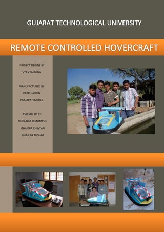
  • 2. REMOTE CONTROLLED HOVERCRAFT A PROJECT REPORT Submitted in partial fulfillment of the requirements for the award of the certificate Of DIPLOMA IN MECHANICAL ENGINEERING BY VYAS TAJAGNA PARTHESHKUMAR 106750319015 PATEL JAIMIN BHARATBHAI 106750319002 PRAJAPATI MEHUL RAMESHBHAI 106750319034 GAJERA CHINTAN PARSHOTTAMBHAI 106750319030 GAJERA TUSHAR JAYSUKHBHAI 106750319018 DHOLARIA DHRMESH LAXMANBHAI 106750319023 UNDER THE GUIDENCE OF MR R.P.PRAJAPATI MR D.M.RASAMIYA MR N.K.TRIPATHI MR.HARDIP PANDYA MR.NILESH DOSHI DEPARTMENT OF MECHANICAL ENGINEERING F.D.(MUBIN) INSTITUTE OF ENGINEERING AND TECHNOLOGY,DAHEGAM PIN-382308, GANDHINAGAR, GUJARAT, INDIA
  • 3. CERTIFICATE This is to certify that, Mr. VYAS TAJAGNA PARTHESHKUMAR From F.D.( MUBIN) Institute of engineering & Technology college having Enrollment no.106750319015 has completed Report on the Semester –VI Project Report having title Remote Control Hovercraft. In a group consisting of 6 persons under the guidance of the Mr.NileshTripathi , Mr.DipakRasamiya and Mr.RakeshPrajapati. Institute Guide- UDP Head of Department DATE
  • 4. The purpose of our project is to construct a functioning hovercraft designed through fundamental principles. Through this design project, we explore the process of engineering from initial design to product construction. We were forced plan around material limitations and me constraints. We produced a vehicle capable of hovering and forward motion. Hovercrafts are multi-purpose vehicles which can travel across various types of terrain with no alteration. The overall purpose for this design project is to build a hovercraft which can carry various payloads, across land and water. This air cushioned vehicle (ACV) can be used for numerous different applications including military, aid, transportation of building supplies, etc. This report will outline the design process as well as the final selected design. It also includes sections on fabrication and testing of the hovercraft and all its components. Also included in this report are detailed design drawings, detailed budget, a list of calculations done for the project.
  • 5. We place on record and warmly acknowledge the continuous encouragement, invaluable supervision, timely suggestions and inspired guidance offered by our guide MR. RAKESH PRAJAPATI, Professor, Department of Mechanical Engineering, in bringing this project to a successful completion. We are grateful to MR. DEEPAK RASAMIYA, Head of the Department of Mechanical engineering, for permitting us to make use of the facilities available in the department to carry out the project successfully. Last but not the least we express our sincere thanks to all of our friends who have patiently extended all sorts of help for accomplishing this undertaking. We are thankful to MR. NILESH TRIPATHI and MR. LALBHAI THAKORE for their support for electric equipment’s and also thanks to MR. HARDIP PANDYA for technical advice. We are thankful to MR. NILESH DOSHI for guiding us in purchasing equipment’s and also thankful to MR. SHAILESH AMIN, MR. KAMLESH PATEL, MR. KALPESH NAI. Finally we express our gratefulness to those who are directly or indirectly responsible for successful completion of this project.
  • 6. I). ABSTRACT……………………………………………………………………………………..………………………………………………………………...I II). ACKNOWLEDGMENT……………………………………………………………………………………………………………………………………….II III). TABLE OF CONTENTS……………………………………………………………………………………………………………………………………..III IV). LIST OF FIGURES……………………………………………………………………………..…………………………………………………………….IV V). LIST OF TABLES………………………………………………………………………………………………………………………………………………..V VI). NOMECLATURE 1). ACRONYMS………………………………………………………………………………………………………………………………………………VI 2). LIST OF SYMBOLS……………………………………………………………………………………………………………………………........VII 1 HISTORY…………….…………………………………………………………………………………………………………………………………………..002 2 ABOUT PROJECT 2.1 INTRODUCTION…………………………………………………………………………………………………………………………………….004 2.2 OBJECTIVE…………………………………………………………………………………………………………………………………………….005 3 SELECTION OF EQUIPMENT 3.1 PROPULSION EQUIPMENT..…………………………………………………………………………………………………………………..007 3.2 LIFT EQUIPMENT…………………………………………………………………………………………………………………………………..008 3.3 BODY MATERIAL…….…………………………………………………………………………………………………………………………….009 3.4 SKIRT MATERIAL….……………………………………………………………………………………………………………………………….009 3.5 POWER SOURCE….……………………………………………………………………………………………………………………………….010 3.6 BODY DESIGN……………………………………………………………………………………………………………………………………….010 4 DETAIL DESIGN 4.1 LIFT…………………………………………………………………….……………………….……………………………………………………….012 4.2 PROPULSION……………………………………………………………………………….……………………………………………………….014 4.3 PLATFORM & SKIRT……………………………………………………………………..……………………………………………………….016 5 MANUFACTURING…..……………………………………………………………………………..……………………………………………………..019 6 CONTROLLING……………………………………………………………………………………………………………………………..………………..023 7 TESTING………………………………………………………………………………………………………….……………………………………………..026 8 CONCLUSION AND REFERANCES 8.1 CONCLUSION………………………………………………………………………………………………………………………………………..030
  • 7. 8.2 REFERANCES………………………………………………………………………………………….……………………………………………..030 VII) BILL OF MATERIAL………………………………………………………………………………………………….…………………………………..VIII VIII) PROJECT SCHEDULE………………………………………………………………………………………………………………………………………X IX) CPM AND PERT ANALYSIS…………………………………………………………………………………………………………………………….XI X) BUDGET………………………………………………………………………………………………………………………………………….……………XII XI) CALCULATION………….……………………………………………………………………………………………..……………………….…………XIII XII) DESIGN……………………….……………………………………………………………………………………………………..………….…………..XIV XIII) MOMENTS AT WORK……………………………………….……………………………………………………………………………………….XXII
  • 8. 1 HOVERCRAFT PRINCIPAL DESIGN………….…………………………………………………………………………………………………..…..004 2 SELECTED PROPELLER ………………………………………………………………………………………………………………………….………..012 3 LIFT MOUNTING DESIGN ……………………………………………………………………………………………………………………..………..013 4 SELECTED MOTOR …………………………………………………………………………………………………………………………………………014 5 MOTOR SUPPORT ………………………………………………………………………………………………………………………………………….015 6 FAN DUCT ……………………………………………………………………………………………………………………………………………..………016 7 PLATFORM DESIGN …………………………………………………………………………………………………………………………………......017 8 SKIRT DESIGN ………………………………………………………………………………………………………………………………………….......018 9 PLATFORM CONSTRUCTION ……………………………………………………………………………………………………………………......020 10 LIFT MOUNTING CONSTRUCTION………………………………………………………………………………………………………………..020 11FAN DUCT CONSTRUCTION……………………………………………………………………………………………………………..…………..020 12 MOTOR SUPPORT……………………………………………………………………………………………………………………………….……….021 13 SKIRT CONSTRUCTION…………………………………………………………………………………………………………………………..…….021 14 ASSEMBLY……..…………………………………………………………………………………………………………………………………………….021 15 FINAL CONSTRUCTION…………………………………………………………………………………………………………………………………022 16CIRCUIT DESIGN……………………………………………………………………………………………………………………………………….....024 17REMOTE AND RECIEVER……………………………………………………………………………………………………………………………….024 18 BATTERY………………………………………………………………………………………………………………………………………………………025 19 MOTOR………………………………………………………………………………………………………………………………………………………..025 20 SERVOMOTOR……………………………………………………………………………………………………………………………………………..025
  • 9. 1 PROPULSION EQUIPMENT SELECTION MATRIX.……………………………………………………………………………………………..007 2 LIFT EQUIPMENT SELECTION MATRIX…..………………………………………………………………………………………………………..008 3 BODY MATERIAL SELECTION MATRIX……………………………………………………………………………………………………………..009 4 SKIRT MATERIAL SELECTION MATRIX……………………………………………………………………………………………………………..009 5 POWER SOURCE SELECTION MATRIX……………………………………………………………………………………………………………..010 6 BODY DESIGN SELECTION MATRIX…..…………………………………………………………………………………………………………….010 7 TERRAIN TESTING RESULT……………………………………………………………………………………………………………………………..028 8 BILL OF MATERIAL………………………………………………………………………………………………………………………………………….VIII 9 PROJECT SCHEDULE…………………………………………………………………………………………………………………………………………..X 10 CRITICAL PATH METHOD ANALYSIS………………………………………………………………………………………………………………..XI 11 BUDGET…………………………………………………………………………………………………………………………………………………………XII
  • 10. 1).ACRONYMS  ACV = AIR CUSHION VEHICAL  UFO = UNDENTIFIED FLYING OBJECT  ESC = ELECTRONIC SPEED CONTROLLER  BOM = BILL OF MATERIAL  LI-PO= LITHIUM POLYMER  CPM = CRITICAL PATH METHOD  BEC = BATTERY ELLIMINATOR CIRCUIT
  • 11.
  • 12. There have been many attempts to understand the principles of high air pressure below hulls and wings. To a great extent, the majority of these can be termed "ground effect" or "water effect" vehicles rather than hovercraft. The principal difference is that a hovercraft can lift itself while still, whereas the majority of other designs require forward motion to create lift. These active-motion "surface effect vehicles" are known in specific cases as ekranoplan and hydrofoils. The first mention in the historical record of the concepts behind surface-effect vehicles that used the term hovering was by Swedish scientist Emanuel Swedenborg in 1716 In 1915, Austrian Dagobert Müller (1880 - 1956) built the world's first "water effect" vehicle. Shaped like a section of a large aero foil (this creates a low pressure area above the wing much like an aircraft), the craft was propelled by four aero engines driving two submerged marine propellers, with a fifth engine that blew air under the front of the craft to increase the air pressure under it. Only when in motion could the craft trap air under the front, increasing lift. The vessel also required a depth of water to operate and could not transition to land or other surfaces. Designed as a fast torpedo boat, the Versuchsgleitboot had a top speed over 32 knots (59 km/h). It was thoroughly tested and even armed with torpedoes and machine guns for operation in the Adriatic. It never saw actual combat, however, and as the war progressed it was eventually scrapped due to lack of interest and perceived need, and its engines returned to the Air Force. In 1931, Finnish aero engineer Toivo J. Kaario began designing a developed version of a vessel using an air cushion and built a prototype Pintaliitäjä (Surface Soarer), in 1937.[4] Kaario's design included the modern features of a lift engine blowing air into a flexible envelope for lift. Kaario never received funding to build his design, however.[citation needed] Kaario's efforts were followed closely in the Soviet Union by Vladimir Levkov, who returned to the solid-sided design of the Versuchsgleitboot. Levkov designed and built a number of similar craft during the 1930s, and his L-5 fast-attack boat reached 70 kn (130 km/h) in testing. However, the start of World War II put an end to Levkov's development work. During World War II, an engineer in the United States of America, Charles Fletcher, invented a walled air cushion vehicle. Because the project was classified by the U.S. government, Fletcher could not file a patent.
  • 13.
  • 14. A hovercraft is a vehicle capable of traveling over most surfaces on a cushion of air trapped under the body for lift. Air propellers, water propellers, or water jets usually provide forward propulsion. Air- cushion vehicles can attain higher speeds than can either ships or most land vehicles due to lower frictional forces and use much less power than helicopters of the same weight. Figure 1 above illustrates the operational principles and basic components of a typical hovercraft. Specifically for our hovercraft, there are three main design groups: the lift, thrust, and steering systems. The arrangement of the hovercraft is similar to that shown in Figure 1. The propeller shown must be designed for a vehicle as typical fans act by creating vortices to mix the air, reducing the ejected air’s translational kinetic energy and significantly reducing efficiency. We outline key features of the three main groups below. Lift System The hovercraft relies on a stable cushion of air to maintain sufficient lift. The air ejected from the propeller is separated by a horizontal divider into pressurized air utilized for the aircushion and momentum used for thrust. The weight distribution on top of the deck is arranged so that the air is distributed the air from the rear of the deck throughout the cushion volume in an approximately even fashion to provide the necessary support. The skirt extending below the deck provides containment, Figure 1 HOVER CRAFT PRINCIPAL DESIGN
  • 15. improves balance, and allows the craft to traverse more varied terrain. We maintain the rigidity of the skirt by filling the air-tight skirt with the same pressurized air diverted towards lift. Thrust System The air not directed to the cushion and skirt is propelled backwards, providing forward thrust to the craft. The size of the propeller, rpm output of the engine, and height of the lift/thrust divider are the determining parameters for the thrust force. A thrust duct channeling the air into the propeller can provide up to a 15% increase in efficiency [Universal Hovercraft]. The limiting factor for the thrust is the air flow available to direct backwards since our primary concern is providing pressurized air for air cushion and lift. As a result, our forward speed is limited but maintainable. Steering System Since a hovercraft lacks the same frictional and drag effects as boats or cars, steering must be approached without precise control in mind. This is especially true in our case as the power supply is limited. Rudders are a main source of steering and are attached to the rear of the duct to direct the flow of air and the direction of the subsequent momentum transfer from the air to the craft. The driver controls the movement of the rudders through a joystick located in the front of the craft. A throttle on the engine situated next to the driver allows him to vary the speed of the craft, allowing for a smaller radius of turning once proper driving techniques are mastered. Because of the air cushion effect, the driver may influence the steering by shifting his weight nearer to any of the four sides of the deck. For example, a shift right turns the hovercraft to the right. In the remainder of the report, we discuss our design and construction processes, the results from testing the craft, the problems associated to our design and construction, and possible improvements. Our goal is to present a clear description of hovercraft history, design concepts, and fundamentals, and to incorporate these into a well thought out design to be considered for manufacturing. We expect that our hovercraft will successfully complete the course, will achieve maximum top speed with minimal cost, will be aesthetically pleasing to the client and spectators, will be reliable and durable for use in multiple runs and will be safe for all concerned.
  • 16.
  • 17. Once our list of concepts was completed we created a screening matrix from them. The matrix was used to evaluate each concept against each client need. The evaluation system we employed was: for each concept and client need a −, 0 or + was assigned to indicate a negative response, a neutral response and a positive response respectively. This evaluation was done by each team member individually. Once the individual screening was completed, we assembled as a team to compare our results, and form a master screening matrix, with which are all in agreement - this is what is presented beginning on the following tables. TABLE 1 : PROPULSION EQUIPMENT SELECTION MATRIX Equipment safe durable Lightweight Easytomanufacture Easytodesign portable Costeffective Marketavailability THRUST POWER Single rocket - - - - - 0 - - Double rocket - - - - - 0 - - Single motor + + + + + + + + Double motor + + + + 0 + + + Diesel engine 0 + 0 0 0 0 - 0 Petrol engine 0 + 0 0 0 0 - 0 POWER SOURCE Single fan – single battery + + + + + + + + Double fan – double battery + + + + 0 + 0 + FAN TYPE Turbo fan - 0 - - 0 0 - 0 Propeller – glass - - 0 - - 0 - 0 Propeller – polycarbonate + + + + + + + + Propeller – wood + + + 0 0 + + + STEERING SYSTEM Mounting table - - - - - - - - Rudder system + + + + + + + +
  • 18. TABLE 2 : LIFT EQUIPMENT SELECTION MATRIX Equipment safe durable Lightweight Easytomanufacture Easytodesign portable Costeffective Marketavailability LIFT POWER Single motor + + + + + + + + Double motor + + + + + + 0 + Diesel engine 0 + 0 0 0 0 - 0 Petrol engine 0 + 0 0 0 0 - 0 Leaf blower + + - - - 0 - 0 Vacuum cleaner + + - - - - - + POWER SOURCE Single fan – single battery + + + + + + + + Double fan – double battery + + + + 0 + 0 + PROPELLER TYPE Turbo fan - 0 - - 0 0 - 0 Propeller – glass - - 0 - - 0 - 0 Propeller –poly carbonate + + + + + + + + Propeller – wood + + + 0 0 + + +
  • 19. TABLE 3 : BODY MATERIAL SELECTION MATRIX Equipment safe durable Lightweight Easytomanufacture Easytodesign portable Costeffective Marketavailability Carbon fiber + + + - - + - - Cardboard + - + + + + 0 + Aluminium + + 0 0 0 + 0 + Fiberglass + + 0 0 0 + - 0 Glass - 0 0 0 0 + - + Paper + - + + + + + + Steel + + - 0 0 + 0 + Light weight wood + + 0 + 0 + 0 + Heavy weight wood + + 0 0 0 + 0 + Plastic + + + + + + 0 + Sheet metal + + - 0 0 + - + Waterproof wood + + - 0 0 + - + Foam + + + + + + + + TABLE 4 : SKIRT MATERIAL SELECTION MATRIX Equipment safe durable Lightweight Easytomanufacture Easytodesign portable Costeffective Marketavailability Rubber + 0 + + + + + + Plastic + + + + + + + + Paper + - + + + + + + Cloth + + + + + + 0 + Neoprene + 0 + 0 + + + 0 Cushion + + + + + + 0 + Nylon + + + + + + 0 + Oiled paper + - + + + + + + polyethylene + + + 0 + + + +
  • 20. TABLE 5 : POWER SOURCE SELECTION MATRIX Equipment safe durable Lightweight Easytomanufacture Easytodesign portable Costeffective Marketavailability Battery + + + + + + + + Storage battery + + - 0 0 + - + Chemical - - + 0 0 - + 0 Solar power + - + 0 0 + - 0 Wind power from lift fan + 0 + 0 0 + - 0 TABLE 6 : BODY DESIGN SELECTION MATRIX Equipment safe durable Lightweight Easytomanufacture Easytodesign portable Costeffective Marketavailability Easytoassemble appearance Ellipse + + + 0 0 + 0 0 - - Square + + + + + + + + + 0 Rectangle + 0 + + + + + + + 0 Triangle + + + 0 0 + + - + - Saucer + + + 0 - + 0 0 - 0 Circular (like a UFO) + + + - - + 0 - - 0 Rectangle (rounded corner) + + + + + + + + + + Aerodynamic + + + - - + - 0 0 + Life boat + + + + + + + + + +
  • 21.
  • 22. 4.1.1 Design Specifications The lift system was designed to supply airflow to the air cushion in order to lift the weight of the hovercraft, including the desired payload, giving a total lifting weight capacity of 100 kilograms to allow for battery weight and additional mounted devices. The system itself was required to meet a set of requirements, as detailed below.  It was to be of light weight, as this was one of the general requirements for all components.  The system should be small given the special restraints present on the platform.  The design should be simple, as a complex design would lead to further complications with the potential to increase the overall size of the system. 4.1.2 Propeller Design Propellers are best when a low flow rate and high static pressure is required. Given that a high flow rate and comparatively low static pressure was required in order to achieve lift, an axial flow fan was selected as the most suitable fan type for this application. A detailed analysis of the variables present in axial fan design was carried out to determine which characteristics best suited this application. There are two main parameters in fan design which influence the characteristics of a fan; the blade pitch, and the number of blades. In general, the rotational speed, diameter, flow rate and static pressure are all specified prior to selecting a fan. SELECTED PROPELLER AS PER THE TABLE 1 4.1.3 Mounting structure design As seen in Figure 3 raising the motor vertically upwards a height of 6 inches gives this design two major advantages. First it removes the risk of the fan damaging the skirt during deflation, because the skirt cannot deflate in close proximity to the blades. The main reason for this selection is the ability to funnel the air flow into a smaller cross section as well as keeping the skirt Fan material out of the vicinity of the fan blades. Figure 2 SELECTED PROPELLER
  • 23. SELECTED MOUNTING FOR LIFTING SYSTEM Figure 3 LIFT MOUNTING DESIGN In order to provide cushion, flow of air must be guided properly towards the base. As shown in the figure 3 the mounting has been kept on the raised platform so that air coming from the outside can be guided through narrow region to the base. 4.1.4 Motor design The propulsion motors are used to drive the propellers, providing thrust to accelerate the hovercraft. The motors required a high degree of controllability, the ability to turn on/off quickly and operate over a variety of operational speeds. To achieve this an electric motor was required, as no other engine can achieve the high degree of controllability needed. Due to the rotational properties of the vectored thrust design, a motor was required with a high power to weight ratio. Able to provide high power levels, whilst remaining light weight, so not to restrict the rotation of the propulsion system. Further the motor size must remain small enough not to restrict the flow into the propeller, in a direct drive configuration. Based on this it was determined A brushless electric motor was required over a brushed motor, able to provide more power and lower Electromagnetic interference. Size restrictions further limited selection to an in-runner motor over an out runner, being significantly smaller, allowing for higher flow and thrust efficiencies.
  • 24. SELECTED BRUSHLESS MOTOR AS PER THE TABLE 2 Propulsion is defined as the forces required to cause motion over a given terrain. The basic principle of hovercraft propulsion is momentum theory. Momentum theory in principle, describes motion of the platform based on a reactive force to the change in momentum of airflow accelerated via a propulsion system. Using dimensionless coefficients of thrust and power, a propeller and power house have been selected based on these principles. 4.2.1 Design Specifications Several design criteria were identified for the propulsion system. The main requirement was the need to maintain maneuverability of the craft by providing the ability to apply forces in the forward, back and sideward directions. This ensures sufficient maneuverability to control the hovercraft in accordance with operational scenarios identified for mine detection regimes. Additional requirements, beyond providing thrust, include obtaining the highest efficiency system at the lowest weight and power costs. As the special limitations of the platform are significant this also becomes an important criteria for selection. The design specifications are summarized below:  Propulsion systems must be independent of the lift system  Provide thrust forces to overcome the inertial and drag loadings on the craft  The platform must have the capacity to DE accelerate to rest in the same time  Maintain a constant velocity at operational of 5 m/s Figure 4 SELECTED MOTOR
  • 25.  Provide thrust forcing in all directions outward of the platform to ensure sufficient maneuver- ability for autonomy  Be of high efficiency, and fit within the spatial bounds of the platform 4.2.2 Propeller Design Propeller which can be used in lift system same like it is used in propulsion system. 4.2.3 Mounting structure design There were several requirements determined for the design of the propulsion mount. These included limitlessly rotate the thrust vector 360 degrees, the ability to resist deflection as a result of thrusting, and simple and easy manufacture and assembly. Furthermore, with safety was an important consideration due to the rotation of a fast moving propeller. It was to be ensured that the rotation of the two propulsion mounts could be achieved independently without interference. The air not directed to the cushion and skirt is propelled backwards, providing forward thrust to the craft. The size of the propeller, rpm output of the engine, and height of the lift/thrust divider are the determining parameters for the thrust force. A thrust duct channeling the air into the propeller can provide up to a 15% increase in efficiency [Universal Hovercraft]. The limiting factor for the thrust is the air flow available to direct backwards since our primary concern is providing pressurized air for air cushion and lift. As a result, our forward speed is limited but maintainable. SELECTED MOUNTING FOR PROPULSION SYSTEM Propulsion motor has been placed on the base through triangular shaped extruded support as shown in the figure. In order to introduce steering effect flat panels have been placed just behind the motor. The panels are movable through servo motor. Figure 5 MOTOR SUPPORT
  • 26. 4.2.4 Motor design Motor which can be used in lift system same like it is used in propulsion system. 4.2.5 Fan duct design Similar to the lifting motor, air flow from propulsion has to be directed through guide walls as shown in the figure. This panels provide support to the steering panels as well. SELECTED FAN DUCT DESIGN 4.3.1 Top plate design The top plates primary function is to house and support all sub systems as well as form the top seal of the pressure chamber, and hence requires a high level flexural rigidity to avoid undue deflection with the potential of damaging the lift fan which is mounted within the pressure chamber. Moreover a high compressive modulus is required to endure repetitive application of torque on the bolts which hold the primary engine mounts, safety tether points and sealing ring. Reliability; in particular the ability to replace and the ability to modify mounting points were assigned the greatest priority in the design considerations, given the high probability of modification of the position of subsystems being mounted on the top plate. A sandwiched structure was specifically chosen to ensure a marginal Figure 6 FAN DUCT
  • 27. penalty in weight for exponential gains in stiffness and strength. SELECTED PLATFORM DESIGN 4.3.2 Skirt design Skirts were first implemented in hovercraft designs in the 1960's to assist with containment of the air cushion. By acting as a flexible sidewall to the air cushion, skirts led to a decrease in the horsepower requirements of hovercrafts and an increase in several performance parameters, namely; air cushion performance, stability and obstacle clearance. Skirts have been implemented in several different configurations, each offering different advantages to the ACV's performance. There are many considerations to undertake when choosing the configuration suitable for a crafts application, including drag, stability and maneuverability requirements of the craft. 4.3.2.1 Design Specification Skirt configuration is an area of ongoing research in industry and different skirt designs over varying performance characteristics. Benchmarking of small hovercraft under two meters has been done to obtain empirical data on the most common configurations used for small craft. Four main configu- rations were identified; the segmented skirt (22%), open-loop bag skirt (74%), the bag and segment combination and the pericell or jupe skirt. Furthermore, combinations of these sets could be used to splice performance characteristics of differing configurations. Figure 7 PLATFORM DESIGN
  • 28. A set of design criteria were generated for skirt configuration selection:  The drag association of the skirt should be minimized due to the application of the hovercraft. This is to ensure that the probability of landmine detonation through skirt contact is minimized.  As active control of the hovercraft in pitch and roll is not being attempted inherent stability of the platform is of high importance. The skirt must therefore control stability of the platform to maximum disturbances in pitch or roll.  The skirt must be adaptable to the platform shape and able to be both fastened and shaped to the preceding hull design.  The hover height of a hovercraft is achieved through obtaining the correct skirt depth and cushion pressure. The skirt must therefore achieve a hover height clearance of 50 mm to the bottom of the hull. SELECTED SKIRT DESIGN AS PER THE TABLE 4 Figure 8 SKIRT DESIGN
  • 29.
  • 30. Below is the detailed outline of the construction process we used. Each section is accompanied by a detailed schematic diagram detailing the dimensions of the materials used as well as pictures taken during construction. A listing of the materials used, their costs and sources can be found in the appendix. First of all we made deck as shown in figure, which is made of 2 foam plates- one in blue and second in white foam. The blue plate is for mounting equipment’s and the other, from these two plates- while foam plate is so made that the air may not leak from the skirt. By cutting with iron coil and by cutter as shown in figure, it was cut in half circle of 10" radius in both plates. Now from the center of the half circle, a circular hole is made in center of the second plate. After cutting the circle, a fillet is made of 2" radius on the corner. Idea was left for making lift mounting on base plate to support the motor it was decided to mount the motor so as to give proper direction to the air. For making mounting foam was cut in size of 2" high x 1" thickness for mounting of 9"diameter. Aluminum strip provided on foam to support the motor. After mounting glue is used on base plate i.e. deck, as shown in figure. After making this mounting, it was decided to make fan duct, which is made in rectangular size most commonly. This fan duct is 5" away from the edge but in center. This fan duct is made by blue foam, as shown in figure. Three plates were cut from fan duct in size of 4"x9"x1" two plates and one plate in 4"x11"x1". After that these three plates were joined with each other by glue. After that this glue was completed Figure 9 PLATFORM CONSTRUCTION Figure 11 LIFT MOUNTING CONSTRUCTION Figure 10 FAN DUCT CONSTRUCTION
  • 31. assembly. This fan duct is shown in the figure. After making this fan duct motor mounting was made as shown in figure which is in triangular shape so that it may not be stressed by the vibration of the motor and can remain stable. This mounting is done in size of 2"x10"x12". After mounting, fan duct was stick at the proper distance. After making complete base plate and mounting structure it was decided to make skirt. For making skirt it was desired to use plastic in which from too base plate, only one plate was made of white foam, and joint was made on it. This skirt is made in dimension shown in the figure to make joint of base plate glue tape is used. After skirt joint, the base plate i.e. white plate and blue plate were joined. so that skirt be tightly packed between two plates and air may not be leaked. For joining these two plates with each other, aluminum clamp was used. After joining these two plates, the look of both plates and the look of skirt can remain clear. We have used black color plastic. After completing structure of hovercraft we fixed the electrical equipment’s at the proper place. After assembling the electrical equipment, testing of the project was done. the aim of testing is that to know, that to keep the hovercraft in proper balance:1. Where and how much weight is required over it? 2. Whether there is any leakage of air? 3. And what effect is getting on air of atmosphere and how much it is? So that we can solve the problem if any, in making the body. Now we start the work, after making the body. Complete body is made of blue foam. We have used two vertical shades so that there is no adverse effect of outer air, propulsion system, (as this has been shown in figure). So that the specific path may get the air and while lifting air may pass inside, so a net with frame is fixed. Figure 12 MOTOR SUPPORT Figure 13 SKIRT CONSTRUCTION Figure 14 ASSAMBLY
  • 32. After completing the body we have fixed the camera on the front side, as shown in figure. Figure 15 FINAL CONSTRUCTION
  • 33.
  • 34. 6.1 Remote and receiver Four channels were the minimum required to manually control each actuator on the craft: lift system, Thrust vector, differential thrust. The remote and receiver selected was a spare unit held by the University, which had a total of six channels. In particular the remote, or radio, was a FLY SKY CT6B. 6.2 Electronic speed controller (ESC) The electronic speed controller is used as an electrical isolator between the motor and the MCU, Whilst acting as a controller for the electric motor. An Electronic Speed Controller (ESC) is required in order to provide a high degree of controllability and protect the motor from incorrect signals and interference levels. Manufacturers recommendations suggest a 25 A ESC and based on this we selected an available Constant Current: 25A -Max. Current: 30A (for 10 seconds) WAIGHT 16 GM , BEC-2 AMP. Lower rated ESC's were available, however are undesirable due to incompatibility warnings with high powered motors operating near maximum performance limitations and known reliability issues. The selected ESC can operate with up to a 2 cell Lithium Ion Polymer (LiPo), providing automatic Figure 16 CIRCUIT DESIGN Figure 17 REMOTE AND RECIEVER
  • 35. brake settings, battery type recognition, low voltage cut-off protection, startup modes and variable signal timing. 6.3 Battery Due to high costs of a 6 cell battery, a 3 cell LiPo was used, in particular a Hacker 20C with a charge capacity of 2200 mAh. This gives a minimum battery life of 2.7 minutes when motor is run at calculated power of 975 W . It is expected that the endurance of the propulsion system will far exceed this however, as motors will not need to be run at full power for the entire time. 6.4 Motor The propulsion motors are used to drive the propellers, providing thrust to accelerate the hovercraft. Two identical motors are required for a dual vector thrust design. The motors required a high degree of controllability, the ability to turn on/off quickly and operate over a variety of operational speeds. To achieve this an electric motor was required. a brushless electric motor was required over a brushed motor, able to provide more power and lower electromagnetic interference, which reduced landmine detection interference. Size restrictions further limited selection to an in-runner motor over an out runner, being significantly smaller, allowing for higher flow and thrust efficiencies. 6.5 Servomotor Servo motor is used for a changing a direction of rudder and also used for controlling a camera direction. we used a two ball bearing servo for camera controlling and one servo motor used for rudder controlling. Figure 18 BATTERY Figure 19 MOTOR Figure 20 SERVO MOTOR
  • 36.
  • 37. The design criteria for a minimum speed of 5 m/s (18 km/h) was established in order to have an overall better performance than the hovercraft built in 2008-2009 at Dalhousie University. The testing of the speed test was conducted on pavement terrain as it is the best for performance hence why it was selected for the test. If time is adequate speed test will be completed on other surfaces. 1. Hovercraft was placed on a flat surface with adequate room to open full throttle. 2. Controller was turned on, battery plugged in. 3. Lift motor was started. 4. Thrust motor was then throttled up to full throttle. 5. Once hovercraft meets what is perceived as max speed, the throttle was released. The following are the results of the speed test on the hovercraft. Each measurement was repeated twice to ensure accuracy. Results of the speed test were mostly successful. The hovercraft performed really well on pavement and exceeded our design requirement of 5 m/s. Although on the gravel the craft did not meet the 5 m/s, the team believes that the craft performed effectively. The run which was used for the gravel test was less than 100 m in length and therefore the craft was not able to reach maximum speed. Given a longer run of gravel the team believes that the craft could meet the requirement of 5 m/s. Performance on grass was not admirable as there was too much friction which restricted the craft from travelling up to speed. This is usual as it is the toughest surface for hovercrafts to hover. Overall, the speed test was deemed a success. One of the main capabilities of the hovercraft is established that it must be able to work on various types of terrain. This has been established through many other tests but is a simple pass or fail scale whether the hovercraft worked or didn’t on these types of terrain. 1. Hovercraft was placed on the various surfaces. 2. Both engines were turned on. 3. Hovercraft was driven around and if performance was satisfactory a pass grade given.
  • 38. Terrain tests were deemed a large success as the hovercraft was capable of operating on all smooth services, while grass provided it much difficulty to thrust. However literature available online shows that grass is one of the hardest surfaces for a hovercraft to traverse because the craft does not get good lift separation between the ground, grass, and skirt. On all other surfaces (cement, gravel, water, and sand) the hovercraft was able to both lift and thrust and steer adequately to provide control of operation. This test was also deemed a success, as in almost all cases the hovercraft was able to perform as desired. With respect to the low performance on grass, this could be solved through a more powerful motor in either lift, thrust, or both. This would allow the craft to lift higher and gain more separation, power through the separation which is already occurring, or both, respectively. TABLE 7 : TERRAIN TESTING RESULTS TERRAIN TEST # PASS FAIL Cement 1  2  3  Gravel 1  2  3  Grass 1  2  3  Water 1  2  3  Sand 1  2  3 
  • 39.
  • 40. 8.1 Conclusion To date, the authors of this report has successfully designed and manufactured an operational hover- craft. Remote control of this hovercraft has been achieved and a comprehensive set of performance tests implemented, confirming the design specification under ideal operating conditions. While the autonomous functionality of the hovercraft, including active yaw control and way point navigation, hasn't reached the final stage of testing and troubleshooting due to time constraints, the extensive design effort applied to these systems provides a solid foundation for further work in this area. 8.2 References  http://www.rqriley.com/hc-calc.html  http://www.hovercraft.com/content/  http://en.wikipedia.org/wiki/Hovercraft  https://sites.google.com/site/kearnsbryan/HoverCalculations-ShaftSizing.xls  https://sites.google.com/site/kearnsbryan/HovercraftDesignToolsrev3-20-08.xls  http://www.model-hovercraft.com/calculator.html  http://4wings.com.phtemp.com/tip/bag.html  Theory & Design of Air Cushion Craft By Liang Yun, Alan Bliault  Principles of hovercraft By Dr TOM margerisom  Hovercraft design and construction Gordon H. Elsley, Anthony John Devereux
  • 41. The Bill of Materials (BOM) is a comprehensive list of all the components on the hovercraft. The BOM is separated into the main systems of the platform for which each is numbered. The numbering system is summarized as follows: 115-XX-YY-ZZ(D)(T)(A)(V) 1. 115 - the project number 2. XX - The System Number (a) 01 - Deck (b) 02 - Lift (c) 03 - Skirt (d) 04 - Propulsion (e) 05 - Electronics/Mechatronics (f) 06 - Body (g) 07 - Assembly 3. YY - The System Subassembly Number 4. ZZ - The Item Number 5. D - The item number should be followed with a D if design is required 6. V - The item number should be followed with a V if it's a vendor item Drawing Numbers follow the same convention. TABLE 8 : BILL OF MATERIAL ID NUMBER SECTION ITEM VENDOR OR DESIGN AMOUNT DESIGN NO DECK 115-01-01-01D DECK TOP BASE PLATE DESIGN 1 115-01-01-01115-01-01-02D DECK BOTTOM BASE PLATE DESIGN 1 115-01-02-01V DECK U CLAMP (ALLUMINUM) VENDOR 7 115-01-03-01V DECK GLUE TAPE VENDOR 20 ft 115-01-04-01V DECK PLASTIC STRIPE (BLACK) VENDOR 12 ft LIFT 115-02-01-01D LIFT LIFT MOUNT DESIGN 1 115-02-01-01 115-02-02-01D LIFT MOTOR SUPPORT STRIPE (ALLUMINUM) VENDOR 1 115-02-03-01V LIFT 2 x 3cm SCREW VENDOR 2 115-02-04-01V LIFT FEVICOL VENDOR 50 ml 115-02-05-01V LIFT 4 x 8mm SCREW VENDOR 4
  • 42. SKIRT 115-03-01-01V SKIRT PLASTIC SQUARE VENDOR 2.5 x 4 ft 115-03-01-02D SKIRT PLASTIC (CUT IN SHAPE) DESIGN 1 115-03-01-02 115-03-02-01V SKIRT GLUE TAPE VENDOR 15 ft PROPULSION 115-04-01-01D PROPULSION FAN DUCT DESIGN 1 115-04-01-01115-04-01-02D PROPULSION RUDDER DESIGN 3 115-04-02-02V PROPULSION CYCLE SPOKE VENDOR 4 115-04-03-01D PROPULSION MOTOR SUPPORT DESIGN 1 115-04-03-01 115-04-03-02V PROPULSION 4 x 8mm SCREW VENDOR 4 115-04-04-01V PROPULSION FEVICOL VENDOR 50 mL ELECTRONICS / MECHATRONICS 115-05-01-01V ELECTRONICS BRUSHLESS MOTOR VENDOR 2 115-05-01-02V ELECTRONICS ELECTRONIC SPEED CONTROLLER (ESC) VENDOR 2 115-05-02-01V ELECTRONICS 11.1 V LI-PO BATTERY VENDOR 1 115-05-03-01V ELECTRONICS SERVO MOTOR VENDOR 3 115-05-04-01V ELECTRONICS CAMERA VENDOR 1 115-05-04-02V ELECTRONICS CAMERA MOUNTING VENDOR 1 115-05-04-03V ELECTRONICS CAMERA BATTERY (9V) VENDOR 1 115-05-05-01V ELECTRONICS RECIEVER VENDOR 1 115-05-05-01V ELECTRONICS REMOTE VENDOR 1 115-05-01-03V ELECTRONICS PROPELLER VENDOR 2 BODY 115-06-01-01D BODY CABINE DESIGN 1 115-06-01-01 115-06-02-01D BODY SPOILER DESIGN 1 115-06-02-01 115-06-03-01D BODY AIR VANE DESIGN 1 ASSEMBLY 115-01-00-00AS DECK DECK DESIGN 1 115-AS-00-00 115-02-00-00AS LIFT LIFT DESIGN 1 115-03-00-00AS SKIRT SKIRT DESIGN 1 115-04-00-00AS PROPULSION PROPPULSION DESIGN 1 115-06-00-00AS BODY BODY DESIGN 1
  • 43. TABLE 9 : PROJECT SHEDULE SR NO TASK NAME DURATION START DATE FINISH DATE 1 Define project 2 days 01-02-13 02-02-13 2 Project planning 5 days 04-02-13 08-02-13 3 Prepare a simple design 8 days 09-02-13 17-02-13 4 Market survey 4 days 18-02-13 22-02-13 5 Prepare a final design 11 days 25-02-13 10-03-13 6 Purchase a equipment from market 7 days 11-03-13 19-03-13 7 Manufacturing 4 days 18-03-13 01-04-13 8 Assembly 7 days 02-04-13 10-04-13 9 Testing 5 days 11-04-13 17-04-13 10 Problem solving or rework 5 days 18-04-13 24-04-13 11 Prepare a final report 8 days 25-04-13 04-05-13
  • 44.
  • 45. The following section outlines a detailed budget of all the necessary parts which were purchased in order to build the hovercraft. The final budget can be seen in Table 9. The budget is within the allotted budget which the Department of Mechanical Engineering at Ahmedabad gave to My team. TABLE 11 : BUDGET SR.NO ITEM RATE QUANTITY TOTAL RATE IN RS ROBOKITS INDIA , JUDGES BUNGLOW , AHMEDABAD 1 11.1 V LI-PO BATTERY 2500/- 1 2500/- 2 BATTERY CHARGER 1000/- 1 1000/- 3 BRUSHLESS MOTOR 950/- 2 1900/- 4 CAMERA MOUNTING 1500/- 1 1500/- 5 CAMERA WITH DVR 3550/- 1 3550/- 6 CHARGER SMPS 180/- 1 180/- SPHERE HOBBIES , PALDI , AHMEDABAD 7 REMOTE WITH RECIEVER 2900/- 1 2900/- 8 PROPELLER (PAIR) 250/- 2 500/- 9 SERVO MOTOR 820/- 1 820/- 10 SERVO EXTENSION 320/- 2 640/- SHIVCO HOBBEY CENTRE , SHIVRANJANI CROSS ROAD , AHMEDABAD 11 ELECTRONIC SPEED CONTROLER (ESC) 975/- 2 1950/- 12 T CONNECTOR 55/- 4 220/- 13 GOLD CONNECTOR 50/- 6 300/- 14 WIRE 58/- 1 ft 58/- EXTRA 15 SCREW,NUT AND BOLT, PLASTIC,GLUE,FOAM ETC SERVICE TAX 5% 500/- 16 900/- TOTAL 18918/-
  • 46. WE ARE USE HOVERCRAFT CALCULATOR FROM FOLLOWING LINKS : (I) https://sites.google.com/site/kearnsbryan/HovercraftDesignToolsrev3-20-08.xls (II) https://sites.google.com/site/kearnsbryan/HoverCalculations-ShaftSizing.xls (III) http://www.rqriley.com/hc-calc.html (IV) http://www.model-hovercraft.com/calculator.html
  • 47. PROJECTION PROJECT 115 :- REMOTE CONTROLES HOVERCRAFT PART NO 115-01-01-01 PART DESCRIPTION DECK (PLATEFORM) DRAWN BY VYAS TAJAGNA .P. MATERIAL FOAM ALL DIMENSIONS ARE IN INCH DATE QUANTITY 2 SCALE NA INSTITUTE NAME F.D. (MUBIN) INSTITUTE OF ENGINEERING AND TECHNOLOGY
  • 48. PROJECTION PROJECT 115 :- REMOTE CONTROLES HOVERCRAFT PART NO 115-02-01-01 PART DESCRIPTION LIFT MOUNTING DRAWN BY VYAS TAJAGNA .P. MATERIAL FOAM ALL DIMENSIONS ARE IN INCH DATE QUANTITY 1 SCALE NA INSTITUTE NAME F.D. (MUBIN) INSTITUTE OF ENGINEERING AND TECHNOLOGY
  • 49. PROJECTION PROJECT 115 :- REMOTE CONTROLES HOVERCRAFT PART NO 115-03-01-02 PART DESCRIPTION SKIRT DRAWN BY VYAS TAJAGNA .P. MATERIAL PLASTIC ALL DIMENSIONS ARE IN INCH DATE QUANTITY 1 SCALE NA INSTITUTE NAME F.D. (MUBIN) INSTITUTE OF ENGINEERING AND TECHNOLOGY
  • 50. PROJECTION PROJECT 115 :- REMOTE CONTROLES HOVERCRAFT PART NO 115-04-01-01 PART DESCRIPTION FAN DUCT WITH RUDDER DRAWN BY VYAS TAJAGNA .P. MATERIAL FOAM / ACRYLIC ALL DIMENSIONS ARE IN INCH DATE QUANTITY SCALE NA INSTITUTE NAME F.D. (MUBIN) INSTITUTE OF ENGINEERING AND TECHNOLOGY
  • 51. PROJECTION PROJECT 115 :- REMOTE CONTROLES HOVERCRAFT PART NO 115-04-03-01 PART DESCRIPTION MOTOR SUPPORT FOR PROPULSION DRAWN BY VYAS TAJAGNA .P. MATERIAL FOAM ALL DIMENSIONS ARE IN INCH DATE QUANTITY 1 SCALE NA INSTITUTE NAME F.D. (MUBIN) INSTITUTE OF ENGINEERING AND TECHNOLOGY
  • 52. PROJECTION PROJECT 115 :- REMOTE CONTROLES HOVERCRAFT PART NO 115-06-01-01 PART DESCRIPTION CABIN DRAWN BY VYAS TAJAGNA .P. MATERIAL FOAM ALL DIMENSIONS ARE IN INCH DATE QUANTITY 1 SCALE NA INSTITUTE NAME F.D. (MUBIN) INSTITUTE OF ENGINEERING AND TECHNOLOGY
  • 53. PROJECTION PROJECT 115 :- REMOTE CONTROLES HOVERCRAFT PART NO 115-06-02-01 PART DESCRIPTION SPOILER DRAWN BY VYAS TAJAGNA .P. MATERIAL FOAM ALL DIMENSIONS ARE IN INCH DATE QUANTITY 1 SCALE NA INSTITUTE NAME F.D. (MUBIN) INSTITUTE OF ENGINEERING AND TECHNOLOGY
  • 54. PROJECTION PROJECT 115 :- REMOTE CONTROLES HOVERCRAFT PART NO 115-AS-00-00 PART DESCRIPTION FINAL ASSEMBLY DRAWN BY VYAS TAJAGNA .P. MATERIAL NA ALL DIMENSIONS ARE IN INCH DATE QUANTITY NA SCALE NA INSTITUTE NAME F.D. (MUBIN) INSTITUTE OF ENGINEERING AND TECHNOLOGY