SlideShare a Scribd company logo
1 of 13
GE Electronic Refrigeration Diagnostics J1 Connector Page 2-4 J2 Connector Page 5,6 J3 Connector   Page 7  BPO encoder diagnostics J4 Connector Page 8 J5 Connector  Page 9 J7 Connector Page 10 J8, J9, J11 and J12 Connections Page 11 defrost operation page 12 Inverter compressor page 13 Training and Technical Support Team  15-9-07
J1 Connector  Thermistor and Model Select Connector  (Overview) ,[object Object],[object Object],[object Object],[object Object],[object Object],[object Object]
J1 Connector   Thermistors Pin 2  «FF2» Thermistor.  Not used on all models.  Measure the thermistor resistance by reading between the wire connected to this Pin and the wire connected tp Pin 5.  Measure this thermistor voltage by reading between Pin 2 and Pin 5 Voltage should be between  2.8 and  3.5 V DC with a good thermistor. Pin 1  «FF1» Thermistor.  Not used on all models.  If used, measure thermistor resistance by reading the wire connected to this pin and the wire connected to Pin 5.  Measure this thermistor voltage by reading between Pin 1 and Pin 5.  Voltage should be between 2.8 and 3.5 V DC with a good thermistor. Pin 3  «FZ» Thermistor.  Based on the resistance of this thermistor, the processor on the main board determines when to turn the compressor on or off.  Measure thermistor resistance by reading between the wire connected to this pin and the wire connected to Pin 5.  Measure this thermistor voltage by reading between Pim 3 and Pin 5.  Voltage should be between 2.8 and 3.5 V DC with a good thermistor. Pin 4  Evaporator Thermistor based on resistance of this thermistor, the processor on the main board determines if the heater will come on for defrost and when to terminate defrost  Measure thermistor resistance by reading between the wire connected to this Pin and the wire connected to Pin 5.  Measure this thermistor voltage by reading between Pin 4 and Pin 5.  Voltage should be between 2.8 and  3.5 V  DC with a good thermistor. Pin 5.  Common connection for thermistors and model select.  (+5 V DC)  Measure supply voltage for thermistors by reading between this Pin and Pin  3 on connector J4.
Thermistor Values 166.8 K -40 120.5 K -31 12.7 K 41 16.3 K 32 21 K 23 27.6 K 14 36.4 K 5 48.4 K -4 65 K -13 88 K -22 Resistance in k ohms Temperature in Degrees F 10 K 50 7.8 K 59 1.2 K 140 1.5 K 131 1.8 K 122 2.2 K 113 2.6 K 104 3.2 K 95 4 K 88 5 K 77 6.2 K 68 Resistance in k ohms Temperature in degrees F
  J2 Connector Fan Motor Connections ,[object Object],[object Object],[object Object],[object Object],[object Object]
    J2 Connector  Fan Motor Connections Pin 1.  Evaporator Fan Tachometer provides feed back from fan motor.  This feedback tells the processor what speed the fan motor is running.  Check for voltage between Pin 1 and Pin 3.  The voltage should be 6.3 V DC. Pin 2.  Personality input to the board on some models with a FF fan motor. Pin 3.  Common lead to all fan motors.  Pin 3 to Pin 8, 13.7 V DC. Pin 4.  Evaporator Fan.  Pin 4 to Pin 3.  Between 4 V DC and 12.4 V DC, +/- 10 %, depending on fan speed. Pin 5.  Condenser Fan.  Pin 5 to Pin 3.  Between 4 V DC and 12.4 V DC,  +/- 10 %, depending on fan speed on inverter models, 12.4V DC on non-inverter models. Pin 6.  Fresh Food Fan (when used) Pin 6 to Pin 3.  Between 4 V DC and 12.4 V DC, +/- 10 %, depending on fan speed. Pin 7.  Quick Chill MC   Fan (when used).  Pin 7 to Pin 3.  13.7 V DC, +/- 10%. Pin  8.  Fan power supply.  +13.7 V DC.  Pin 3 to Pin 8. To test Evaporator fan motor look for 12 volts between pin 3 and pin 8 AND 4,8,or 12 volts between pin 3 and pin 4. To test Condenser  fan motor look for 12 volts between pin 3 and pin 8 AND 8or 12 volts between pin 3 and pin 5.
J3 Connector   Damper motor and Encoder Connections   Pins  1 thru  4 are the damper stepper motor connections.  Pins 5 thru 10 are the Encoder board connection.  J3 Pin 1 to J4 Pin 3,  6 V DC Traveling Voltage or 2.3 V DC standing voltage. J3 Pin 2 to J4 Pin 3,  6 V DC Traveling Voltage or 2.3 VDC standing voltage. J3 Pin 3 to J4 Pin 3,  6 V DC  Traveling Voltage or 2.3 V DC standing voltage. J3 Pin 4 to J4 Pin 3,  6 V DC Traveling voltage or 2.3 V DC standing voltage. J3 Pin 10.  Double Function Pin Encoder Connection Not on all models or on inverter compressor models used to transmit speed data to compressor inverter module on some models.  1.5 to 3 V DC measured between  J3 Pin 10 and J4 Pin 3. J3 Pin 5.  Encoder Connection.  Not used on all models. J3 Pin 6.  Encoder Connection.  Not used on all models. J3 Pin 7.  Encoder Connection.  Not used on all models. J3 Pin 8.  Encoder Connection.  Not used on all models. J3 Pin 9.  Encoder Connection . Not used on all models. See Encoder table on how to diagnose the encoder.
J4 Connector FF,FZ,  Dispenser, and Quick Chill Drawer  Serial Data Communications Connections     Pin 2  Dispenser Board, FF,FZ, And Quick Chill Drawer +13V DC Power supply. Pin 1  Dispenser, FF, FZ, And Quick Chill Drawer Data Communications on some models. Pin 4  Dispenser Board Input 1.  (Input from the Dispenser Board on some models) Pin 3  Board DC Common Ground. Pin 5  Dispenser Board Input 2  (Input from the Dispenser Board on some models) Some pins might not have a wire connected to them depending upon model features.
J5 Connector   Quick Chill Drawer Connections – Not used on all models Pin 1.  Chiller Drawer Damper Motor  Connection  13.7 V DC Pin 1to Pin 2. Pin 2.  Chiller Drawer Damper Motor Connection  13.7 V DC Pin 1 to Pin 2. Pin 3.  Chiller Drawer Damper Motor Connection  13.7 V DC Pin 3 to Pin 4  Not used on all models.  Pin 4.  Chiller Drawer Damper Motor Connection  13.7 V DC Pin 3 to Pin 4  Not used on all models.  Pin 5.  Chiller Drawer Thermistoer Connection.  Measure resistance by reading between wires connected tp Pin 5 and Pin 6.  Measure voltage by reading between Pin 5 and J 4  Pin 3 Voltage should be 5V DC.  Pin 6.  Chiller Drawer Thermistor Connection.  Measure resistance by reading between wires connected to Pin 5 and Pin 6.  Measure voltage by reading between J4 Pin 3 and Pin 6.  Voltage  should be between 2.8 and  3.5 V DC with a good thermistor. Measure thermistor resistance with the wires disconnected from the board. Measure voltages with the wires connected to the board
J7 Connector   120 V AC Outputs and Inputs   Pin 9.  Neutral Connection to Main Board. Pin 8.  Blank.   Pin 7. Input  FZ Door 120V AC With door open between Pin 7 and Pin 9. Pin 6. Input FF Door 120V CA With the door open between Pin 6 and Pin 9. Pin 5.  Output Quick Chill Heater 120V CA measured between Pin 5 and Pin 9. Pin 4.  Input for auger from FZ door interlock switch.  120V AC between Pin 4 and Pin 9 with the FZ door closed. Pin 3.  Output to dispenser water valve solenoid.  120V AC between Pin 3 and Pin 9 with the FZ Door closed and cradle depressed.  Pin 2.  Output to cube solenoid with Fz Door closed, cubes selected, and cradle switch depressed, 120V AC between Pin 2 and Pin 9. Pin 1. Output to auger motor.  120V AC between Pin 1 and Pin 9.  FZ Door closed, cubes  or crushed selected, and switch depressed. J7
   J8, J9, J11 and J12 Connections 120 VAC input and output connections J8 Output to compressor 120 VAC measured between  J8 and J7, Pin 9.   J8 J9 Output to Defrost Circuit 120 VAC mesured between  J9 and J7, Pin 9.   J9 J11 Line in to Board.  120 VAC measured between J11 and J7, Pin 9. J11 J12 Output to  Monogram drain pan heater  120 VAC measured between  J12 et J7 Pin 9.  The pan heater is on only during defrost. J12 J8 J9 J11 J12
Diagnosing Defrost Operation ,[object Object],[object Object],[object Object],[object Object],[object Object],Defrost Line Neutral
Inverter compressor diagnosis WARNING:  When the refrigerator is plugged in, 120 VAC is always present at the inverter. ,[object Object],[object Object],[object Object],[object Object],J15 connector 4-6 vdc output to inverter

More Related Content

What's hot

J.M. Smith, Hendrick Van Ness, Michael Abbott, Mark Swihart - Introduction to...
J.M. Smith, Hendrick Van Ness, Michael Abbott, Mark Swihart - Introduction to...J.M. Smith, Hendrick Van Ness, Michael Abbott, Mark Swihart - Introduction to...
J.M. Smith, Hendrick Van Ness, Michael Abbott, Mark Swihart - Introduction to...HEMAMALINIKANASAN
 
Introduction to refrigeration systems
Introduction to refrigeration systemsIntroduction to refrigeration systems
Introduction to refrigeration systemsVishu Sharma
 
To investigate the effect of a change in the cross section area on the temper...
To investigate the effect of a change in the cross section area on the temper...To investigate the effect of a change in the cross section area on the temper...
To investigate the effect of a change in the cross section area on the temper...Salman Jailani
 
Carel mastercella manuel d'utilisation
Carel mastercella manuel d'utilisationCarel mastercella manuel d'utilisation
Carel mastercella manuel d'utilisatione-genieclimatique
 
49539990 burner-management-system
49539990 burner-management-system49539990 burner-management-system
49539990 burner-management-systemMowaten Masry
 
Heat rate of thermal power plant
Heat rate of thermal power plantHeat rate of thermal power plant
Heat rate of thermal power plantManohar Tatwawadi
 
How to Size a Condensate Return Unit
How to Size a Condensate Return UnitHow to Size a Condensate Return Unit
How to Size a Condensate Return UnitKevin Doyle
 
Eveporation ppt by sachin ;;;;;;;;;;;
Eveporation ppt   by sachin ;;;;;;;;;;;Eveporation ppt   by sachin ;;;;;;;;;;;
Eveporation ppt by sachin ;;;;;;;;;;;sachin kumar
 
Boiler Purging-Logic, Importance & Working
Boiler Purging-Logic, Importance & WorkingBoiler Purging-Logic, Importance & Working
Boiler Purging-Logic, Importance & WorkingTahoor Alam Khan
 
Hakko 936. Gordak 952. diy. analog soldering station. schematic
Hakko 936. Gordak 952. diy. analog soldering station.  schematicHakko 936. Gordak 952. diy. analog soldering station.  schematic
Hakko 936. Gordak 952. diy. analog soldering station. schematictarzan1a
 
Refrigeration PPT to present.ppt
Refrigeration PPT to present.pptRefrigeration PPT to present.ppt
Refrigeration PPT to present.pptBodhiSeal1
 
Design and Fabrication of Thermo Electric Refrigerator
Design and Fabrication of Thermo Electric RefrigeratorDesign and Fabrication of Thermo Electric Refrigerator
Design and Fabrication of Thermo Electric Refrigeratorijtsrd
 
Modulo control nu mc-220_270_00_mem0209_k.pdf
Modulo control nu mc-220_270_00_mem0209_k.pdfModulo control nu mc-220_270_00_mem0209_k.pdf
Modulo control nu mc-220_270_00_mem0209_k.pdfe-genieclimatique
 
Performance calculation for feed water heater
Performance calculation  for feed water heaterPerformance calculation  for feed water heater
Performance calculation for feed water heaterSHIVAJI CHOUDHURY
 
Cooling water system
Cooling water systemCooling water system
Cooling water systemumar farooq
 
introduction to soldering and de-soldering
introduction to soldering and de-solderingintroduction to soldering and de-soldering
introduction to soldering and de-solderingVARUN KUMAR
 

What's hot (20)

J.M. Smith, Hendrick Van Ness, Michael Abbott, Mark Swihart - Introduction to...
J.M. Smith, Hendrick Van Ness, Michael Abbott, Mark Swihart - Introduction to...J.M. Smith, Hendrick Van Ness, Michael Abbott, Mark Swihart - Introduction to...
J.M. Smith, Hendrick Van Ness, Michael Abbott, Mark Swihart - Introduction to...
 
Introduction to refrigeration systems
Introduction to refrigeration systemsIntroduction to refrigeration systems
Introduction to refrigeration systems
 
Cheema
CheemaCheema
Cheema
 
To investigate the effect of a change in the cross section area on the temper...
To investigate the effect of a change in the cross section area on the temper...To investigate the effect of a change in the cross section area on the temper...
To investigate the effect of a change in the cross section area on the temper...
 
Carel mastercella manuel d'utilisation
Carel mastercella manuel d'utilisationCarel mastercella manuel d'utilisation
Carel mastercella manuel d'utilisation
 
49539990 burner-management-system
49539990 burner-management-system49539990 burner-management-system
49539990 burner-management-system
 
Heat rate of thermal power plant
Heat rate of thermal power plantHeat rate of thermal power plant
Heat rate of thermal power plant
 
How to Size a Condensate Return Unit
How to Size a Condensate Return UnitHow to Size a Condensate Return Unit
How to Size a Condensate Return Unit
 
Eveporation ppt by sachin ;;;;;;;;;;;
Eveporation ppt   by sachin ;;;;;;;;;;;Eveporation ppt   by sachin ;;;;;;;;;;;
Eveporation ppt by sachin ;;;;;;;;;;;
 
Boiler Purging-Logic, Importance & Working
Boiler Purging-Logic, Importance & WorkingBoiler Purging-Logic, Importance & Working
Boiler Purging-Logic, Importance & Working
 
Hakko 936. Gordak 952. diy. analog soldering station. schematic
Hakko 936. Gordak 952. diy. analog soldering station.  schematicHakko 936. Gordak 952. diy. analog soldering station.  schematic
Hakko 936. Gordak 952. diy. analog soldering station. schematic
 
Refrigeration
RefrigerationRefrigeration
Refrigeration
 
Refrigeration PPT to present.ppt
Refrigeration PPT to present.pptRefrigeration PPT to present.ppt
Refrigeration PPT to present.ppt
 
Design and Fabrication of Thermo Electric Refrigerator
Design and Fabrication of Thermo Electric RefrigeratorDesign and Fabrication of Thermo Electric Refrigerator
Design and Fabrication of Thermo Electric Refrigerator
 
Modulo control nu mc-220_270_00_mem0209_k.pdf
Modulo control nu mc-220_270_00_mem0209_k.pdfModulo control nu mc-220_270_00_mem0209_k.pdf
Modulo control nu mc-220_270_00_mem0209_k.pdf
 
Desescarche
DesescarcheDesescarche
Desescarche
 
Performance calculation for feed water heater
Performance calculation  for feed water heaterPerformance calculation  for feed water heater
Performance calculation for feed water heater
 
Cooling water system
Cooling water systemCooling water system
Cooling water system
 
Revomax boiler (thermax)
Revomax boiler (thermax) Revomax boiler (thermax)
Revomax boiler (thermax)
 
introduction to soldering and de-soldering
introduction to soldering and de-solderingintroduction to soldering and de-soldering
introduction to soldering and de-soldering
 

Viewers also liked

Service manuals lg_fridge_gr349sqf_gr-349sqf service manual
Service manuals lg_fridge_gr349sqf_gr-349sqf service manualService manuals lg_fridge_gr349sqf_gr-349sqf service manual
Service manuals lg_fridge_gr349sqf_gr-349sqf service manualPaulo Andrade
 
Samsung fjm installation manual
Samsung fjm installation manualSamsung fjm installation manual
Samsung fjm installation manualRui Caçoete
 
Mạch điện máy điều hòa hay nhất
Mạch điện máy điều hòa hay nhấtMạch điện máy điều hòa hay nhất
Mạch điện máy điều hòa hay nhấtle quoc
 
BÀI GIẢNG SỬA CHỮA BOARD MÁY LẠNH 2 CỤM (PHẦN CƠ BẢN)
BÀI GIẢNG SỬA CHỮA BOARD MÁY LẠNH 2 CỤM (PHẦN CƠ BẢN)BÀI GIẢNG SỬA CHỮA BOARD MÁY LẠNH 2 CỤM (PHẦN CƠ BẢN)
BÀI GIẢNG SỬA CHỮA BOARD MÁY LẠNH 2 CỤM (PHẦN CƠ BẢN)Hau Cao Trung
 
Hướng dẫn sửa chữa bếp từ trong thực tế
Hướng dẫn sửa chữa bếp từ trong thực tếHướng dẫn sửa chữa bếp từ trong thực tế
Hướng dẫn sửa chữa bếp từ trong thực tếĐiện Tử Bách Khoa
 
Air conditioning for large multistory buildings
Air conditioning for large multistory buildingsAir conditioning for large multistory buildings
Air conditioning for large multistory buildingspnazila
 

Viewers also liked (11)

Carrier inverter Split System
Carrier inverter Split System Carrier inverter Split System
Carrier inverter Split System
 
Carrier Split Room Air Conditioner
Carrier Split Room Air ConditionerCarrier Split Room Air Conditioner
Carrier Split Room Air Conditioner
 
Service manuals lg_fridge_gr349sqf_gr-349sqf service manual
Service manuals lg_fridge_gr349sqf_gr-349sqf service manualService manuals lg_fridge_gr349sqf_gr-349sqf service manual
Service manuals lg_fridge_gr349sqf_gr-349sqf service manual
 
Ac repair in delhi
Ac repair in delhiAc repair in delhi
Ac repair in delhi
 
Samsung fjm installation manual
Samsung fjm installation manualSamsung fjm installation manual
Samsung fjm installation manual
 
Mạch điện máy điều hòa hay nhất
Mạch điện máy điều hòa hay nhấtMạch điện máy điều hòa hay nhất
Mạch điện máy điều hòa hay nhất
 
BÀI GIẢNG SỬA CHỮA BOARD MÁY LẠNH 2 CỤM (PHẦN CƠ BẢN)
BÀI GIẢNG SỬA CHỮA BOARD MÁY LẠNH 2 CỤM (PHẦN CƠ BẢN)BÀI GIẢNG SỬA CHỮA BOARD MÁY LẠNH 2 CỤM (PHẦN CƠ BẢN)
BÀI GIẢNG SỬA CHỮA BOARD MÁY LẠNH 2 CỤM (PHẦN CƠ BẢN)
 
Sua chua tu lanh
Sua chua tu lanhSua chua tu lanh
Sua chua tu lanh
 
Hướng dẫn sửa chữa bếp từ trong thực tế
Hướng dẫn sửa chữa bếp từ trong thực tếHướng dẫn sửa chữa bếp từ trong thực tế
Hướng dẫn sửa chữa bếp từ trong thực tế
 
Air conditioning system
Air conditioning systemAir conditioning system
Air conditioning system
 
Air conditioning for large multistory buildings
Air conditioning for large multistory buildingsAir conditioning for large multistory buildings
Air conditioning for large multistory buildings
 

Similar to Electronic Refrigeration Diagnosis

Chromation systems 24-channel-usb-connected-led-controller-v3
Chromation systems 24-channel-usb-connected-led-controller-v3Chromation systems 24-channel-usb-connected-led-controller-v3
Chromation systems 24-channel-usb-connected-led-controller-v3nadimsh90
 
How to Build Your Own Power Supply
How to Build Your Own Power SupplyHow to Build Your Own Power Supply
How to Build Your Own Power SupplyEng. Emad Al-Atoum
 
Temperature Controlled DC fan using Thermistor
Temperature Controlled DC fan using ThermistorTemperature Controlled DC fan using Thermistor
Temperature Controlled DC fan using ThermistorZaheer Basha
 
Presentation OutDoorSwithGear(AIS) .pptx
Presentation OutDoorSwithGear(AIS) .pptxPresentation OutDoorSwithGear(AIS) .pptx
Presentation OutDoorSwithGear(AIS) .pptxRAJKIRANR3
 
Integrated circuit
Integrated circuitIntegrated circuit
Integrated circuitddsshukla
 
Secure SRT322_User__Installation_instructions
Secure SRT322_User__Installation_instructionsSecure SRT322_User__Installation_instructions
Secure SRT322_User__Installation_instructionsDomotica daVinci
 
Service training top therm chiller 1 6 k w-eng_01.10.2014
Service training top therm chiller 1 6 k w-eng_01.10.2014Service training top therm chiller 1 6 k w-eng_01.10.2014
Service training top therm chiller 1 6 k w-eng_01.10.2014Nickna16
 
XLSEMI XL140 2A 380KHz 18V Buck DC to DC Converter
XLSEMI XL140 2A 380KHz 18V Buck DC to DC ConverterXLSEMI XL140 2A 380KHz 18V Buck DC to DC Converter
XLSEMI XL140 2A 380KHz 18V Buck DC to DC Converterdegarden
 
Implementationof Single Phasing, Over Voltage, Under Voltage, Protection of T...
Implementationof Single Phasing, Over Voltage, Under Voltage, Protection of T...Implementationof Single Phasing, Over Voltage, Under Voltage, Protection of T...
Implementationof Single Phasing, Over Voltage, Under Voltage, Protection of T...IJERA Editor
 
cw5000 5200 water chiller manual
cw5000 5200 water chiller manualcw5000 5200 water chiller manual
cw5000 5200 water chiller manualxlntchillers .com
 

Similar to Electronic Refrigeration Diagnosis (20)

pe lab manual
pe lab manualpe lab manual
pe lab manual
 
Fe 712 instruction_sheet_1
Fe 712 instruction_sheet_1Fe 712 instruction_sheet_1
Fe 712 instruction_sheet_1
 
XCRW
XCRWXCRW
XCRW
 
Kenr6200 01
Kenr6200 01Kenr6200 01
Kenr6200 01
 
Unit 1-2-b
Unit 1-2-bUnit 1-2-b
Unit 1-2-b
 
CDG_11.PDF
CDG_11.PDFCDG_11.PDF
CDG_11.PDF
 
95ZJ_8N.PDF
95ZJ_8N.PDF95ZJ_8N.PDF
95ZJ_8N.PDF
 
Chromation systems 24-channel-usb-connected-led-controller-v3
Chromation systems 24-channel-usb-connected-led-controller-v3Chromation systems 24-channel-usb-connected-led-controller-v3
Chromation systems 24-channel-usb-connected-led-controller-v3
 
Fanuc 10
Fanuc 10Fanuc 10
Fanuc 10
 
How to Build Your Own Power Supply
How to Build Your Own Power SupplyHow to Build Your Own Power Supply
How to Build Your Own Power Supply
 
Temperature Controlled DC fan using Thermistor
Temperature Controlled DC fan using ThermistorTemperature Controlled DC fan using Thermistor
Temperature Controlled DC fan using Thermistor
 
TOP412GN.pdf
TOP412GN.pdfTOP412GN.pdf
TOP412GN.pdf
 
Presentation OutDoorSwithGear(AIS) .pptx
Presentation OutDoorSwithGear(AIS) .pptxPresentation OutDoorSwithGear(AIS) .pptx
Presentation OutDoorSwithGear(AIS) .pptx
 
Integrated circuit
Integrated circuitIntegrated circuit
Integrated circuit
 
Secure SRT322_User__Installation_instructions
Secure SRT322_User__Installation_instructionsSecure SRT322_User__Installation_instructions
Secure SRT322_User__Installation_instructions
 
Service training top therm chiller 1 6 k w-eng_01.10.2014
Service training top therm chiller 1 6 k w-eng_01.10.2014Service training top therm chiller 1 6 k w-eng_01.10.2014
Service training top therm chiller 1 6 k w-eng_01.10.2014
 
XLSEMI XL140 2A 380KHz 18V Buck DC to DC Converter
XLSEMI XL140 2A 380KHz 18V Buck DC to DC ConverterXLSEMI XL140 2A 380KHz 18V Buck DC to DC Converter
XLSEMI XL140 2A 380KHz 18V Buck DC to DC Converter
 
Implementationof Single Phasing, Over Voltage, Under Voltage, Protection of T...
Implementationof Single Phasing, Over Voltage, Under Voltage, Protection of T...Implementationof Single Phasing, Over Voltage, Under Voltage, Protection of T...
Implementationof Single Phasing, Over Voltage, Under Voltage, Protection of T...
 
Implementationof Single Phasing, Over Voltage, Under Voltage, Protection of T...
Implementationof Single Phasing, Over Voltage, Under Voltage, Protection of T...Implementationof Single Phasing, Over Voltage, Under Voltage, Protection of T...
Implementationof Single Phasing, Over Voltage, Under Voltage, Protection of T...
 
cw5000 5200 water chiller manual
cw5000 5200 water chiller manualcw5000 5200 water chiller manual
cw5000 5200 water chiller manual
 

Recently uploaded

Spiritual Life Quote from Shiva Negi
Spiritual Life Quote from Shiva Negi Spiritual Life Quote from Shiva Negi
Spiritual Life Quote from Shiva Negi OneDay18
 
Benefits of Co working & Shared office space in India
Benefits of Co working & Shared office space in IndiaBenefits of Co working & Shared office space in India
Benefits of Co working & Shared office space in IndiaBrantfordIndia
 
Tuesday Morning inspirational quotes and images.pdf
Tuesday Morning inspirational quotes and images.pdfTuesday Morning inspirational quotes and images.pdf
Tuesday Morning inspirational quotes and images.pdfMehtab Ali
 
Call Girls Dubai O525547819 Favor Dubai Call Girls Agency
Call Girls Dubai O525547819 Favor Dubai Call Girls AgencyCall Girls Dubai O525547819 Favor Dubai Call Girls Agency
Call Girls Dubai O525547819 Favor Dubai Call Girls Agencykojalkojal131
 
The 5 sec rule - Mel Robins (Hindi Summary)
The 5 sec rule - Mel Robins (Hindi Summary)The 5 sec rule - Mel Robins (Hindi Summary)
The 5 sec rule - Mel Robins (Hindi Summary)Shakti Savarn
 
Virtue ethics & Effective Altruism: What can EA learn from virtue ethics?
Virtue ethics & Effective Altruism: What can EA learn from virtue ethics?Virtue ethics & Effective Altruism: What can EA learn from virtue ethics?
Virtue ethics & Effective Altruism: What can EA learn from virtue ethics?Mikko Kangassalo
 

Recently uploaded (6)

Spiritual Life Quote from Shiva Negi
Spiritual Life Quote from Shiva Negi Spiritual Life Quote from Shiva Negi
Spiritual Life Quote from Shiva Negi
 
Benefits of Co working & Shared office space in India
Benefits of Co working & Shared office space in IndiaBenefits of Co working & Shared office space in India
Benefits of Co working & Shared office space in India
 
Tuesday Morning inspirational quotes and images.pdf
Tuesday Morning inspirational quotes and images.pdfTuesday Morning inspirational quotes and images.pdf
Tuesday Morning inspirational quotes and images.pdf
 
Call Girls Dubai O525547819 Favor Dubai Call Girls Agency
Call Girls Dubai O525547819 Favor Dubai Call Girls AgencyCall Girls Dubai O525547819 Favor Dubai Call Girls Agency
Call Girls Dubai O525547819 Favor Dubai Call Girls Agency
 
The 5 sec rule - Mel Robins (Hindi Summary)
The 5 sec rule - Mel Robins (Hindi Summary)The 5 sec rule - Mel Robins (Hindi Summary)
The 5 sec rule - Mel Robins (Hindi Summary)
 
Virtue ethics & Effective Altruism: What can EA learn from virtue ethics?
Virtue ethics & Effective Altruism: What can EA learn from virtue ethics?Virtue ethics & Effective Altruism: What can EA learn from virtue ethics?
Virtue ethics & Effective Altruism: What can EA learn from virtue ethics?
 

Electronic Refrigeration Diagnosis

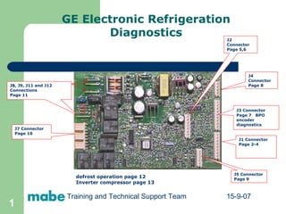
  • 1. GE Electronic Refrigeration Diagnostics J1 Connector Page 2-4 J2 Connector Page 5,6 J3 Connector Page 7 BPO encoder diagnostics J4 Connector Page 8 J5 Connector Page 9 J7 Connector Page 10 J8, J9, J11 and J12 Connections Page 11 defrost operation page 12 Inverter compressor page 13 Training and Technical Support Team 15-9-07
  • 2.
  • 3. J1 Connector Thermistors Pin 2 «FF2» Thermistor. Not used on all models. Measure the thermistor resistance by reading between the wire connected to this Pin and the wire connected tp Pin 5. Measure this thermistor voltage by reading between Pin 2 and Pin 5 Voltage should be between 2.8 and 3.5 V DC with a good thermistor. Pin 1 «FF1» Thermistor. Not used on all models. If used, measure thermistor resistance by reading the wire connected to this pin and the wire connected to Pin 5. Measure this thermistor voltage by reading between Pin 1 and Pin 5. Voltage should be between 2.8 and 3.5 V DC with a good thermistor. Pin 3 «FZ» Thermistor. Based on the resistance of this thermistor, the processor on the main board determines when to turn the compressor on or off. Measure thermistor resistance by reading between the wire connected to this pin and the wire connected to Pin 5. Measure this thermistor voltage by reading between Pim 3 and Pin 5. Voltage should be between 2.8 and 3.5 V DC with a good thermistor. Pin 4 Evaporator Thermistor based on resistance of this thermistor, the processor on the main board determines if the heater will come on for defrost and when to terminate defrost Measure thermistor resistance by reading between the wire connected to this Pin and the wire connected to Pin 5. Measure this thermistor voltage by reading between Pin 4 and Pin 5. Voltage should be between 2.8 and 3.5 V DC with a good thermistor. Pin 5. Common connection for thermistors and model select. (+5 V DC) Measure supply voltage for thermistors by reading between this Pin and Pin 3 on connector J4.
  • 4. Thermistor Values 166.8 K -40 120.5 K -31 12.7 K 41 16.3 K 32 21 K 23 27.6 K 14 36.4 K 5 48.4 K -4 65 K -13 88 K -22 Resistance in k ohms Temperature in Degrees F 10 K 50 7.8 K 59 1.2 K 140 1.5 K 131 1.8 K 122 2.2 K 113 2.6 K 104 3.2 K 95 4 K 88 5 K 77 6.2 K 68 Resistance in k ohms Temperature in degrees F
  • 5.
  • 6.     J2 Connector Fan Motor Connections Pin 1. Evaporator Fan Tachometer provides feed back from fan motor. This feedback tells the processor what speed the fan motor is running. Check for voltage between Pin 1 and Pin 3. The voltage should be 6.3 V DC. Pin 2. Personality input to the board on some models with a FF fan motor. Pin 3. Common lead to all fan motors. Pin 3 to Pin 8, 13.7 V DC. Pin 4. Evaporator Fan. Pin 4 to Pin 3. Between 4 V DC and 12.4 V DC, +/- 10 %, depending on fan speed. Pin 5. Condenser Fan. Pin 5 to Pin 3. Between 4 V DC and 12.4 V DC, +/- 10 %, depending on fan speed on inverter models, 12.4V DC on non-inverter models. Pin 6. Fresh Food Fan (when used) Pin 6 to Pin 3. Between 4 V DC and 12.4 V DC, +/- 10 %, depending on fan speed. Pin 7. Quick Chill MC Fan (when used). Pin 7 to Pin 3. 13.7 V DC, +/- 10%. Pin 8. Fan power supply. +13.7 V DC. Pin 3 to Pin 8. To test Evaporator fan motor look for 12 volts between pin 3 and pin 8 AND 4,8,or 12 volts between pin 3 and pin 4. To test Condenser fan motor look for 12 volts between pin 3 and pin 8 AND 8or 12 volts between pin 3 and pin 5.
  • 7. J3 Connector Damper motor and Encoder Connections   Pins 1 thru 4 are the damper stepper motor connections. Pins 5 thru 10 are the Encoder board connection. J3 Pin 1 to J4 Pin 3, 6 V DC Traveling Voltage or 2.3 V DC standing voltage. J3 Pin 2 to J4 Pin 3, 6 V DC Traveling Voltage or 2.3 VDC standing voltage. J3 Pin 3 to J4 Pin 3, 6 V DC Traveling Voltage or 2.3 V DC standing voltage. J3 Pin 4 to J4 Pin 3, 6 V DC Traveling voltage or 2.3 V DC standing voltage. J3 Pin 10. Double Function Pin Encoder Connection Not on all models or on inverter compressor models used to transmit speed data to compressor inverter module on some models. 1.5 to 3 V DC measured between J3 Pin 10 and J4 Pin 3. J3 Pin 5. Encoder Connection. Not used on all models. J3 Pin 6. Encoder Connection. Not used on all models. J3 Pin 7. Encoder Connection. Not used on all models. J3 Pin 8. Encoder Connection. Not used on all models. J3 Pin 9. Encoder Connection . Not used on all models. See Encoder table on how to diagnose the encoder.
  • 8. J4 Connector FF,FZ, Dispenser, and Quick Chill Drawer Serial Data Communications Connections   Pin 2 Dispenser Board, FF,FZ, And Quick Chill Drawer +13V DC Power supply. Pin 1 Dispenser, FF, FZ, And Quick Chill Drawer Data Communications on some models. Pin 4 Dispenser Board Input 1. (Input from the Dispenser Board on some models) Pin 3 Board DC Common Ground. Pin 5 Dispenser Board Input 2 (Input from the Dispenser Board on some models) Some pins might not have a wire connected to them depending upon model features.
  • 9. J5 Connector Quick Chill Drawer Connections – Not used on all models Pin 1. Chiller Drawer Damper Motor Connection 13.7 V DC Pin 1to Pin 2. Pin 2. Chiller Drawer Damper Motor Connection 13.7 V DC Pin 1 to Pin 2. Pin 3. Chiller Drawer Damper Motor Connection 13.7 V DC Pin 3 to Pin 4 Not used on all models. Pin 4. Chiller Drawer Damper Motor Connection 13.7 V DC Pin 3 to Pin 4 Not used on all models. Pin 5. Chiller Drawer Thermistoer Connection. Measure resistance by reading between wires connected tp Pin 5 and Pin 6. Measure voltage by reading between Pin 5 and J 4 Pin 3 Voltage should be 5V DC. Pin 6. Chiller Drawer Thermistor Connection. Measure resistance by reading between wires connected to Pin 5 and Pin 6. Measure voltage by reading between J4 Pin 3 and Pin 6. Voltage should be between 2.8 and 3.5 V DC with a good thermistor. Measure thermistor resistance with the wires disconnected from the board. Measure voltages with the wires connected to the board
  • 10. J7 Connector 120 V AC Outputs and Inputs   Pin 9. Neutral Connection to Main Board. Pin 8. Blank.   Pin 7. Input FZ Door 120V AC With door open between Pin 7 and Pin 9. Pin 6. Input FF Door 120V CA With the door open between Pin 6 and Pin 9. Pin 5. Output Quick Chill Heater 120V CA measured between Pin 5 and Pin 9. Pin 4. Input for auger from FZ door interlock switch. 120V AC between Pin 4 and Pin 9 with the FZ door closed. Pin 3. Output to dispenser water valve solenoid. 120V AC between Pin 3 and Pin 9 with the FZ Door closed and cradle depressed. Pin 2. Output to cube solenoid with Fz Door closed, cubes selected, and cradle switch depressed, 120V AC between Pin 2 and Pin 9. Pin 1. Output to auger motor. 120V AC between Pin 1 and Pin 9. FZ Door closed, cubes or crushed selected, and switch depressed. J7
  • 11.    J8, J9, J11 and J12 Connections 120 VAC input and output connections J8 Output to compressor 120 VAC measured between J8 and J7, Pin 9.   J8 J9 Output to Defrost Circuit 120 VAC mesured between J9 and J7, Pin 9.   J9 J11 Line in to Board. 120 VAC measured between J11 and J7, Pin 9. J11 J12 Output to Monogram drain pan heater 120 VAC measured between J12 et J7 Pin 9. The pan heater is on only during defrost. J12 J8 J9 J11 J12
  • 12.
  • 13.