1. IOSR Journal of Engineering (IOSRJEN) www.iosrjen.org
ISSN (e): 2250-3021, ISSN (p): 2278-8719
Vol. 04, Issue 04 (April. 2014), ||V3|| PP 25-28
International organization of Scientific Research 25 | P a g e
Laser Distance Measurement by using web camera
Ahmed A.Hamad , Dhafir A. Dhahir, Bushra.R.Mhdi, Wadah H.Salim
Ministry of Science and Technology ,Laser and Optoelectronic center ,Iraq-Bagdad
Abstract: - In this work the near distance measurement system was presented .The system are consist from
transmitter and receiver .The transmitter is used as semiconductor laser at wavelength 526 nm and the power 5
mw and the receiver are consist of optics part and web camera .The concept of operation is transmit a pulse of
laser and then is received the reflected pulse from the object .The software program was written in C# language
to calculate the object distance .The accuracy of the measurement distance is high. The error in the distance
measurement reach to ±3cm.
Keywords: - distance measurement, laser distance measurement
I. INTRODUCTION
Any self-respecting mobile robot requires some sort of distance measurement sensor or range finding
mechanism. Among the most accessible are ultrasonic range finders, which time the propagation and reaction of
a sonic pulse. ultrasonic rangers, especially when placed in ring configuration, are plagued with fundamental
difficulties that make them unattractive for serious localization.
At the other end of the spectrum are high-end laser rangefinders, which use light instead of sound to determine
distance from time-of-light. These are often bundled with precision optics and mechanisms that allow one to
infer 3D point clouds over large and small " human" distances. Their precision and reliability makes them ideal
for industrial and research applications, but their cost is prohibitive to the hobbyist or researcher on a low
budget.
To solve the problem of optimizing user cost vs. sensor precision and reliability, we consider a different
sensor design. Here, the only materials needed are a laser line generator and a camera (e.g, a cheap webcam).
The principle of operation is simple: one points the line generator and the camera in the same direction, but of
sets them some known distance d off (~ 10cm). The camera sees the laser line, filtered from the rest of the
environment based on brightness and color, which is of set whenever it strikes an object. By calculating the of
set distance from the expected position of the laser line, the distance to the object can be inferred.
II. RANGE SENSOR DESIGN
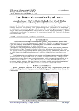
Figure( 1 )shows the arrangement of the webcam and laser pointer. This configuration allow us to
maintain in parallel position both of components, there by facilitating a quick calculation of real distances from
a simple model.
Fig(1) The photograph image of laser distance measurement setup.
2. Laser Distance Measurement by using web camera
International organization of Scientific Research 26 | P a g e
III. GEOMETRY OF THE MODEL
In Figure( 2) the scheme used for the calculation of distance is showed. The distance between the
webcam and laser pointer is defined by H (in centimeters). The distance between the scanner and the object is
defined by D (in centimeters).
Also note that the representation of the scene in the image formed by the webcam lens is the size A"'
B "
,
where AB represents the same scene in real size. On the other hand, the distance between the center of the
image to the location of the beam projected in the images can be defined as pfc (pixels from center), where Ɵ
represents the angle of vision (in radians) formed by projection of the laser beam projected onto the image.
Fig. 2. Scheme of the arrangement of the camera-laser.
The distance D is obtained from the projection of the laser dot on the surface of the object.
With this scheme we can establish the following relation:
D = (1)
The relationship can be raised to obtain the total of pixels per degree of incoming light, here called rpc
(radian per pixel pitch), thus converting each pixel in the image to its corresponding value in centimeters.
The following equation shows rpc in relation with Ɵ:
Ɵ= pfc * rpc (2)
Due to the existence of lens deformations on the webcam, in Equation 2 we consider a parameter which
allows us the correction of alignment, here called
ro (radian offset):
Ɵ = pfc * rpc + ro (3)
To obtain the values of rpc and ro we use a model of linear regression to find the relation between a
dependent variable Y with k explanatory variables xk, which generate a hyper plane of parameters β .Usually
this linear model is defined as:
Y + Ɛ (4)
where Ɛ is a random variable that deals with those uncontrollable factors. The model satisfies the following
general equation:
Y = m X + b (5)
With
3. Laser Distance Measurement by using web camera
International organization of Scientific Research 27 | P a g e
where n, is the total of samples used; m, is the slope of the regression line
(rpc); b, is the value originated by uncontrollable factors (ro) and Y represents Ɵ.
In order to obtain the distance to the object, we introduce the Equation 3 into the Equation 1, each of one in
centimeters:
D (6)
We called this formulation as the Equation of distance calculation.
We define laser beam as the light project by the laser pointer onto the object and captured by a webcam.
For our work, we use a laser pointer that emits green light and its localization onto the images is considered as a
form of introduce the depth information into the image. The process of localization is nuanced by (i) the
presence of illumination into the environment; (ii) the texture of the object pointed by the laser beam, and (iii)
the size of the laser beam projected onto the image (the size of the projected beam depends of the proximity
between the scanner and the object).
IV. RESULTS AND CALCULATIONS
To calibrate the system, we will collect a series of measurements where the range to the target, is known.
The number of pixels the dot is from the centre of the image each time is also needed. Example data is set out
below:
Table 1
Pixels from Centre Actual D (cm)
103 29
81 45
65 58
55 71
49 90
45 109
41 127
39 159
37 189
35 218
Calibration Data
Using the following equation, we can now calculate the actual angle based on the value of h, as well as actual
distance for each data point.
Ø actual = arc tan ( h / D actual)
where:
Ø actual =Actual Angle
D actual = Actual Distance to Measured Target
Once we have a Theta actual for each value, we can discover the relationship that lets us calculate theta
from the number of pixels from image centre. To use a linear relationship, the gain and offset are required.
Though this works well, it does not take into account that the focal plane is a 'plane', rather than curved at a
constant radius around the centre of the camera lens[4].
From the calibration data, we can calculate both Offset & Gain :
Offset (r o) = -0.056514344 radians
Gain (r pc) = 0.0024259348 radians/pixel
Using:
D= hover tan (pf ctimes r pc + r o )
4. Laser Distance Measurement by using web camera
International organization of Scientific Research 28 | P a g e
We can calculate distances, including a error value from the actual distance using the calibration data above:
Table 2( Actual and Calculated Range Data)
V. CONCLUSIONS
One possible improvement that can be made to this camera based Laser range finder is to use a laser
that projects a horizontal line rather than a dot onto a target. With this type of Laser, we could calculate the
range for each column of pixels in the image, rather than just one column as done here. This type of set-up
could be used to locate areas of maximum range as places that a vehicle could steer towards. Likewise, areas
with readings of minimum range would be identified as obstacles to be avoided.
From my initial experiments, the green laser's dot can be hard to distinguish at distances greater than 2 meters.
Also the dot tends to blend into light backgrounds in well lit situations. I feel that a Green Laser may go a long
way to solving these two issues.
REFERENCES
[1] Isaac Cohen and Gerard Medioni. Detecting and tracking objects in video surveillance.In Proceeding of
the IEEE Computer Vision and Pattern Recognition 99,Fort Collins, June 1999.
[2] Brian Gerkey, Kasper Stoy, and Richard T. Vaughan.Player robot server. Institutefor Robotics and
Intelligent Systems Technical Report IRIS-00-391, Universityof Southern California, 2000.
[3] Stephen S. Intille, James W. Davis, and Aaron F. Bobick. Real-time closed worldtracking. In
Proceeding of the IEEE Conference on Computer Vision and Pattern Recognition, pages 928{934, June
1997.
[4] Andrew Ng. Em algorithm. CS229 Class Notes, 2008.
[5] Hai Nguyen. Ros wiki: Camera calibration, 2008.
[6] Sebastian Thrun, Wolfram Burgard, and Dieter Fox. Probabilistic Robotics, chapter 6.3, pages
124-139. MIT Press, 2005.
Pixels from centre Calc D (cm) Actual D (cm) % Error
103 29.84 29 2.88
81 41.46 45 -7.87
65 57.55 58 -0.78
55 75.81 71 6.77
49 93.57 90 3.96
45 110.85 109 1.70
41 135.94 127 7.04
39 153.27 159 -3.60
37 175.66 189 -7.06
35 205.70 218 -5.64