SlideShare una empresa de Scribd logo
1 de 14
Descargar para leer sin conexión
High Power Cold Cathode Electron Tubes for Power Electronics Applications
                         Curtis Birnbach: Advanced Fusion Systems LLC
                             John Kappenman: Storm Analysis LLC


Abstract: While semiconductor-based devices have been predominantly utilized in power electronic
applications, they are fundamentally limited for the extremely high voltage and high power applications.
Designs that have been put forth for current and next generation HVDC and FACTS systems universally
rely on stacks of hundreds of semiconductor devices for operation. Semiconductor designs require
complex balancing networks, snubbers to limit di/dt and dv/dt levels, require extensive cooling, and are
completely vulnerable to arc-related failures.

AFS has introduced a new generation of electron tubes which can, in a single device, handle the voltages
and currents required for current and next generation HVDC and FACTS systems. These electron tubes
were originally developed for high-power microwave electronic warfare applications and have been
modified to suit the unique requirements of the power industry. Individual tubes can simultaneously
handle voltages to one million volts and currents of tens of thousands of amps continuously, making
them well-suited to even EHV FACTS and HVDC applications. These electron tubes do not use filaments
but instead employ a proprietary cold cathode technology, giving them a life expectancy in excess of 25
years. They are built to withstand extreme shock as would be found in the military environment. The
tubes will withstand repeated arcing with no damage, and can operate continuously at temperatures on
the order of 1000 degrees Fahrenheit. As a result, the auxiliary cooling systems commonly needed for
high power semiconductor applications are not needed for electron tubes. This paper will compare the
operating characteristics of AFS electron tubes and compare them to current state-of-the-art
semiconductor devices. A number of applications for electron tubes relevant to this HVDC and FACTS
conference will be discussed.

Background: A seductive trap that many engineers fall into has been described as “Technology for
Technology’s Sake.” In essence, this means that one should not always look at the latest technology for
answers when they can be found in older methods. The electron tube has a long and storied history.
Older-generation electron tubes used filaments to heat cathodes (or as cathodes themselves).
Filaments were the weak link in electron tubes and thermionic cathodes are limited in their current
density, typically no more than 15 amps/cm2. Newer electron tube designs omit the filament in favor of
a cold cathode which works by extracting electrons via a strong electric field. The AFS cathode has been
characterized extensively and has been found to have a maximum rated current density of 500
amps/cm2 in continuous mode and over 80,000 amps/cm2 in the pulse mode. Figure 1 (below) shows
an IV curve of this cathode (for continuous current).
Figure 1: IV Curve of AFS Cathode

AFS through its predecessor corporation, Hudson Research Inc., started building this class of electron
tubes in 1985. The manufacturing processes have been refined and these tubes are in their fourth
generation of design. A new, 250,000 square foot factory dedicated to the manufacture of these
electron devices is currently under construction and demonstrates AFS’ commitment to this industry.
This facility includes extensive testing capabilities that will position it as a premier manufacturing and
test site for power electronics.

Comparison of Electron Tubes and Semiconductor Power Devices: This section will examine the
differences between semiconductors and electron tubes in high power applications. The following table
highlights the primary differences and their implications.

     Failure Mode              Semiconductor Devices                         Electron Tubes
Arcing                   Fail after first arc event           Highly arc resistant
Thermal Sensitivity      Requires elaborate cooling           Can operate up to 1000° F without cooling
Voltage Handling         Individual devices limited to 20KV   Individual devices can handle up to 1.2MV
Current Handling         Individual devices can handle 8KA    Individual Devices can handle >1MA
Circuit Complexity       Very complex circuits required       Very simple circuits

               Table 1: Basic comparison between semiconductors and electron tubes.

Discussion of Failure Modes:            The following discussion provides a more detailed overview is
described of the failure modes and operating limitations of semiconductor devices versus the
improvements available from Electron Tubes, as noted in Table 1.

Arcing: The crystalline structure of semiconductor devices is a non-forgiving insulator. In operation, a
semiconductor can be called on to conduct electricity at one moment and to block its flow at the next.
All semiconductor materials used in power electronics exhibit the piezo-electric effect. This is the cause
of a substantial number of failures and is one of the underlying fundamental limitations of
semiconductors. As the following figure (Fig 2) shows, when an electric field is applied across a typical
semiconductor structure, there is a discontinuity in field strength in the region of the electrodes.


                                                                                                        2
Figure 2. Piezo-electric failure mode of semiconductor devices

This discontinuity translates directly into different amount of expansion due to the piezo-electric effect.
In the areas where there are adjacent zones of differing piezo-electric expansion, the crystal is stressed
in a non-uniform manner, leading to a localized mechanical failure. This manifests itself first as a crack.
This causes the local electric field to increase, and when it passes the insulation standoff rating of the
remaining crystalline material, an arc occurs. This carbonizes the arc path and renders the device
useless. Under these stresses, the crystal essentially tears itself apart.

In this case, the presence of the electrode is the underlying reason for this failure mode, due to the non-
uniformity of the electric field it introduces. Even for a design case of a semiconductor device with a
uniform electrode across its entire face, piezo-electric expansion stress is still an important failure mode.
In the presence of a similarly uniform ground plane, such a device would be able to withstand higher
voltages, but would still eventually fail when the expansion induced by the piezo-electric effect exceeds
the stress modulus of the crystal. A secondary issue is that it is necessary to have electrodes to create
advanced turn-on devices, unless the device is simply limited to a diode.

An electron tube, on the other hand, incorporates a vacuum in a physical space as the insulator.
Vacuum is inherently self-healing, so, even if an arc occurs, it rapidly dissipates and normal operation is
restored. In fact, arcing is a normal condition during processing of electron tubes. Many types of tubes,
such as magnetrons, klystrons and some power triodes, operate under conditions where arcs occur as a
normal part of operation and are shrugged off by the tube.

In electron-beam coating system power supplies, a staple manufacturing technology for the
semiconductor industry, power triode electron tubes are frequently used as output devices because of
their resistance to damage from the arcing that frequently occurs during this process. The fact that the
semiconductor manufacturing industry needs to use tubes to get a reliable process should be an
indicator of the inherent robustness of the devices.

                                                                                                           3
The insensitivity of electron tubes to arcing increases the reliability of a power system in several ways.
Aside from eliminating failures due to transients, they also eliminate the need for elaborate snubber-
type networks to suppress various types of transients that commonly occur in power systems. Reduced
component count translates directly to increased mean-time-between-failures (MTBF), the main metric
of reliability in electric systems.

Thermal Sensitivity: It is well-known and undisputed that semiconductor devices are highly sensitive to
their thermal environment. Once their temperature exceeds a critical value, about 25oC, their
performance rapidly degenerates. Figure 3 (below) shows the efficiency versus temperature curve of
typical semiconductor power devices. Figure 3 also demonstrates the extensive need for cooling that
semiconductors require to avoid operational derating. This extreme temperature limitation usually
needs to be compensated by auxiliary cooling systems and extensive valve hall structure to house and
carefully regulate the semiconductors ambient environments.


                          Figure 3: Thermal efficiency of silicon power devices

When confronted by this data, it is tempting to turn to some of the more exotic semiconductors, such as
silicon carbide, gallium nitride, etc., as a solution to this problem. However, this is not as simple as it
seems. While silicon technology is extremely mature, and high manufacturing yields are the norm, in
the exotic materials, it is difficult to grow crystals of sufficient diameter, with sufficient purity and
freedom from dislocations and twinning, to achieve the same ratings and cost economies as found with
silicon. Even allowing for high-yield production of devices based on these exotic materials, the piezo-
electric effect will still be an important limitation due to the previously discussed single arc failure mode.

In contrast, electron tubes have been demonstrated to operate from -196oC (temperature of liquid
nitrogen) to 500oC with no impact on device performance. This extended operating range means that
auxiliary cooling systems are usually not necessary and that even outdoor apparatus is achievable saving
the costs of expensive valve hall superstructures.

Voltage Handling: At the time of writing this article, the best solid state devices can handle about 20KV.
This means that for a 1,000 kV system, stacks of 60 devices are required just to achieve the required
voltage handling capability. These stacks also usually need to be paralleled to achieve the required
current handling capacity. However, this presumes that only the highest voltage devices are used.
More likely as in recently announced major HVDC expansion projects, the devices used are rated at 8KV
maximum. While the specifics of these designs are not fully known, it is reasonable that given a 75%


                                                                                                            4
rating, to achieve the same 1,000 kV rating, over 170 devices per stack would be required for these
operating voltage levels. It is important to remember that some level of device failure of any in these
stacks needs to be planned for, such that a margin of normal failure can be tolerated. This means
adding additional semiconductor devices into the stack (or press-pack) construction. Also in stack
construction, balancing networks are required to ensure even distribution of voltage across each of the
devices in a stack. Additional support circuitry in the form of snubber circuits is necessary to protect the
semiconductors from sudden voltage and current surges (di/dt and dv/dt) which would lead to arcing
and premature failure. The ability to provide cooling auxiliaries for heat dissipation to all these
semiconductor devices while maintaining increasing voltage withstand (BIL) across the devices also adds
complexity and substantial costs to the overall design, as well as additional possible failure modes. In
short, these complex semiconductor device arrays increase the complexity of a design and lower its
MTBF.

AFS electron tubes are manufactured as single devices with service ratings up to 1.2MV. They take up
substantially less space that their solid state counterparts for any power electronics in excess of 15KV
overall voltage rating. In most practical high power applications, auxiliary cooling is not required for
electron tubes, which further reduces complexity and modes of possible failure.

Current Handling: Individual semiconductor devices, as currently used in the power electronics arena,
typically have maximum ratings on the order of 4 to 5 thousand amps continuous. At least one
manufacturer has reported a peak current capability of “80KA for short periods”, though it is unclear the
specifics on the time withstand and how broadly that may apply for semiconductor devices. Devices
must be paralleled to achieve higher current handling capacity. This is easier said than done and
requires complex balancing networks to ensure even current distribution across all devices. As is the
case with voltage balancing networks, the current balancing networks decrease the reliability of a
system.

Circuit Complexity: As discussed in the preceding two sections, when it is necessary to design for high
voltages and high currents, semiconductor devices require complex support circuitry and extensive
cooling, and even with this are still subject to sudden failure due to voltage or current surges.

Electron tube circuits are very simple due to the single control element present. They are not affected
by voltage or current surges, or high operating temperatures. Therefore in any reasonable comparison
to semiconductor devices, electron tubes seem to be ideal devices for power electronic systems.

Electron Tube Application Ranges: Earlier in this paper the concept of “Technology for Technology’s
sake” was discussed. This concept mandates choosing the right technology for each specific task. It
turns out that while it is possible to build electron tubes to operate at fairly low voltages, once they go
below a certain size, it is cheaper to build and use semiconductor devices, particularly for voltages
substantially below 4KV. In the intermediate range, from 4 kV to 50 kV or so, the choice of tubes or
semiconductors can only be determined on a case by case basis. Over 50 kV, tubes become the
technology of choice. However in all cases where robustness is required, where maintaining proper
cooling is difficult, when requiring operation in high transient environments, tubes are clearly the


                                                                                                          5
technology of choice. Even at lower kV Operating Ranges, electron tubes can offer much higher current
ratings than semi-conductor devices and applications can be now realized for such needs as fault-
current limiting. At operating voltages over 250kV and given the new availability of electron tubes,
semiconductor devices should be viewed as a questionable choice at best.

Voltage and Current Handling Capacity:                As can be seen in Figure 4, modern electron tubes
can handle 4 to 5 orders of magnitude greater voltage and current than the present semiconductor
devices. Unlike semiconductor devices, the overall current and voltage capacity of an electron tube rises
as they get larger. This is based on two factors: the standoff voltage rises proportionally to the physical
size of the tube; and the current handling capacity is based on the number of square centimeters of
cathode material. The cathode is rated at a maximum of 500 Amps/cm2, but in order to assure long
lifetimes, the device is typically only loaded to 250 Amps/cm2. Thus, a typical cathode, of say, 1 inch
height and five inches length would have a continuous current rating in excess of 50KA. This is a fairly
small cathode in this technology. In a tube rated at 500KV, with a 5 inch diameter by one foot long
cathode, the continuous current rating would be 790 kA. This would equate to something like 364BVA
(Billion Volt-Amperes), clearly a value that is way beyond anything likely to be encountered in practical
power systems. Thus, the cathode loading is reduced and the life of the tube is substantially extended,
in essence providing for extreme robustness of the electron tube device in even the largest of high
voltage, high power applications.


                       Figure 4: Electron Tubes (Red) vs. Semiconductors (Blue):
                         Single Device Voltage vs. Current Continuous Capacity

                                                                                                         6
Voltage Drop / Insertion Loss: One of the most important considerations for any power switching
device is its voltage drop, which is also referred to as insertion loss. Typical semiconductor junctions
have a voltage drop of 0.5 to 0.7 volts in the forward conduction mode due to the ohmic drop across the
semiconductor layers. This means that each junction will draw some amount of power, just to get a
signal through. This current translates directly into internal heat due to I2R losses. This is substantial
when you add up the losses for a couple of hundred junctions.

In a cold-cathode field-emission electron tube, the loss situation is vastly different. The electron tube
does not work by trying to push electrons through a crystal. These tubes just have to convince the
electrons to propagate across a vacuum. The propagations of electrons in a vacuum plasma is
essentially lossless, as plasmas exhibit properties akin to superconductors. Thus, the only losses are the
work function loss of the electrodes. In AFS tubes, this equates to about 10 electron volts (also can be
expressed as resistance of ~150 micro-ohms), which is up to ~3 orders of magnitude less than the losses
of a typical semiconductor junction.

Switching Loss: For many FACTS applications, increasing demands are placed on the semiconductor
devices to perform multiple and rapid switching of high voltages and high currents. When a
semiconductor is used for high frequency switching, switching losses during the turn-on and turn-off
operation should be taken into consideration, as these losses can exceed by many times the steady-
state losses of the device as previously discussed.

Most semiconductor manufacturer device specifications indicate that switch turn on and turn off times
increases with Power (VxI) ratings of semiconductor device. Therefore with semiconductor device
switching power levels as low as ~2MVA, the semiconductor device turn-off times can be as long as 200
usec. The longer the switching time, the greater the total losses in the semiconductor device. On the
other hand, Electron tubes again exhibit 3 orders or greater magnitude faster switch transition times
(<100 psec) compared to semiconductor devices. Figure 5 provides a plot of voltage and current during
turn-on of an electron tube device.


                                                                                                        7
Figure 5. Electron Tube current & voltage turn on transition [red is current, purple is voltage, green is electric
                                                     field]

Application Discussion:           The combination of high voltage and current operating ranges of Electron
Tubes combined with other superior attributes of low losses, extended thermal operating range and
failure tolerance make these devices well suited for nearly all existing power electronic applications now
done with semiconductor devices. In addition, the enormous expansion of operating range of the
Electron Tubes also make conceivable new horizons for FACTS devices that were simply unattainable or
impractical with semi-conductor devices. This includes such concepts of fault-current limiters (discussed
later) as well as AC and DC solid-state circuit breakers and other feasible applications in the electric
power industry that Advanced Fusion will demonstrate at future dates.

In regards to all existing HVDC and FACTS systems, Advanced Fusion offers devices that can be direct
replacements or alternatives to the semiconductor counterpart. Virtually any topology that can be
implemented with semiconductor devices can be implemented using electron tubes. Historically,
semiconductors, when first introduced, implemented tube circuits. History has come full circle with the
re-introduction of electron tube technology. One other non-obvious advantage of electron tubes is that
manufacture involves readily available materials and CNC type fabrication approaches. This allows for
the ability to readily customize most electron tubes to meet the unique rating, configuration, and cost
requirements of an application.

Pulsatron & Bi-tron: The electron tube devices can be more concisely described by noting that they fit
into two broad categories as a purely DC operating device or as an AC or bi-directional operating device.
The DC electron tube device called the Pulsatron was originally developed in the mid-1980’s as a
replacement for spark gaps in high voltage pulse modulators. It is an extremely fast (~100 picosecond)

                                                                                                                      8
risetime cold cathode field emission triode. It has subsequently been tested in a variety of circuits and
has been found to be a viable replacement for semiconductor devices in every application over 4000
volts. It has been used in pulse power supplies with output voltages up to 750 KV and 250KA. The
design has been found to scale linearly. The Pulsatron™ is also an advanced turn-on and turn-off device.
It can support closing mode, opening mode and all conventional CW and Pulse operating modes. The
device due to the enormous capability has been likened to a thyristor on steroids.

Recently, a tetrode variant has been developed to respond to the need for a bi-directional device for AC
circuitry. This tube is known as the Bi-tron™, and is functionally comparable to an IGBT in many aspects,
except it can be produced for operation at voltages up to 1.2 MV and current ratings in the hundreds of
KA. As is the case with the Pulsatron, this tube is capable of operating in many modes including high-
speed switching circuits, Class A, AB, B, C, and D amplifiers, flip-flops, Marx generators, to name a few.

AFS is in the process of developing SPICE models of these tubes to facilitate other parties designing
circuits using these devices. These SPICE models are expected to be available during 2011.

Fault Current Limiters: The need for compact efficient Fault Current Limiters (FCL’s) in large power
networks at both distribution and transmission-level voltages is well established. The US Dept. of
Energy has a substantial program to foster development of such systems.

This concept was originally developed for a fusion power project requirement for a DC regulator that
could operate in the MegaVolt and KiloAmp (simultaneous) regime. The requirement was for a
regulator which could regulate from 0 to 100% over an arbitrary time period which could be very short
(μsec’s) or could be as long as several hours. The circuit is shown in Figure 6.


                                   Fig 6: DC Current Regulatorpat pend

AFS is currently developing an AC version of the DC regulator that contains three cold-cathode tubes in
an AC implementation of the classic 2 FET current regulator. In order to extend this circuit to allow AC
operation, a second shunt circuit is added so that there is one control loop for each polarity. The series
regulator element is a Bi-tron™ pat pend bi-directional tetrode and the control functions are implemented
using a pair of Pulsatron cold-cathode DC triodes, one for each polarity of the sine wave. All three tubes

                                                                                                        9
are packaged in a single ruggedized stainless steel housing. This multi-tube assembly is known as the
Faultron™. AFS has designed and is currently constructing a 10 MW continuous rated Fault Current
Limiter Test Stand to support its development and production requirements. The Faultron™ equivalent
circuit is shown below in Figure 7.


                               Fig 7: AC Fault Current Regulatorpat pend

Geomagnetically Induced Current Protection: The threat of Geomagnetically Induced Current (GIC)
events is a well-documented threat to the power grid. NERC has categorized this threat in the “Low
Frequency – High Impact” class; they don’t happen often, but when they do, the results can be
catastrophic. This approach is discussed in more detail in companion paper at this conference. What is
important to stress is the potential consequences from a full-on impact of a severe geomagnetic storm
event: An unprotected grid can be disabled for extended periods of time. In Figure 8 (below), the
Kappenman circuit is shown in Normal, Early Stage of a Fault, and Full Fault mode.


                           Fig 8: Kappenman GIC Neutral Blocking Device


                                                                                                   10
HVDC to 3-Phase AC Inverters: HVDC has been widely utilized for many years in the electric power
industry. While the conversion of AC to DC is very easy, the reverse process is non-trivial. AFS has a
patent-pending HVDC to 3-Phase AC Inverter. This system was designed as a part of our fusion power
program and was configured to provide current limiting from 1 to 100%. It will accept input voltages as
high as 10MV and convert to 3-Phase AC at any standard transmission voltage. The system incorporates
built-in current limiting and a dynamic phase load matching technique which balances out phase to
phase differences in the line that it is connected to. A single phase of the three phase configuration is
shown below in Figure 9.


         Fig 9. AFS HVDC Inverterpat pend: One Phase of Three Shown; Secondaries not Shown

Static Compensators: The Bi-tron and Pulsatron electron tubes bring a new class of design possibilities
to the electric power industry. Virtually any circuit topology that can be implemented with
semiconductors can be implemented with greater simplicity and reliability when using electron tubes.
Static compensation is another major FACTS power electronics area where electron tubes would have
the capacity to make significant inroads. AFS electron tubes provide the ability to build Statcoms, UPFC
and other related devices substantially in much larger MVA sizes than previously possible and for direct
operation at all transmission voltages. The elimination of step-up transformers and many other related
auxiliary systems in transmission applications will dramatically reduce the cost and size of implementing
this critical system control functions.

Circuit Breakers: As is the case with Statcoms and FCLs, electron tube technology will allow
development of a new generation of circuit breakers for both AC as well as DC applications. Several
topologies are currently under development at AFS. Future reports on details of these devices will be
provided at future technical conferences.

Surge Supression - Super Varistor Device & EMP/IEMI Protection: Because the Electron Tube has the
inherent ability to absorb 10’s of Megajoules of energy and can also switch within 10’s of picoseconds,
this device is readily suited to provide transient surge suppression for any source of transient that could
occur on the network. The combination of large energy and ability to operate to EHV voltage levels

                                                                                                        11
makes this device especially key for EHV protection where MOV devices cannot be built to absorb the
amount of energy needed particularly for long duration switching surge events. The ability to control
multiple surges can even allow consideration of reduced BIL ratings to these EHV systems in expensive
devices such as transformers.

Another Low-frequency High Impact threat is that posed by an EMP/IEMI attack. EMP stands for
Electromagnetic Pulse, and is a product of nuclear explosions. It is an expanding spherical wave of very
fast risetime and long duration. Its destructive potential is well-documented. While it is necessary for
an adversary to launch a nuclear attack, the wave couples to transmission lines and the like and destroys
transformers and other major transmission components by overvoltage induced failures. IEMI
(Intentional Electromagnetic Interference) is a technique that produces similar waveforms to EMP but
from electrically-driven and chemically-driven sources. Unlike its EMP counterpart, IEMI can actually
achieve substantially higher electric fields. It is not generally appreciated in the power industry of the
magnitude of pulses that can be produced electrically. Electric fields in excess of 500KV/m have been
reported. These fields are substantially in excess of those contemplated by MIL 188-125, the current
standard for EMP Protection. While MIL 188-125 is nominally directed at high-altitude EMP effects and
protection techniques, the procedures are applicable to a wide range of threats within the energy levels
specified in this document. Unfortunately, this document does not contemplate substantially higher
fields or other conditions which render it ineffective. It is of crucial import that the power industry
recognizes the severity of this threat. Like it’s sister, GIC, this threat, while relatively low in incidence,
has consequences that can rival the worst case scenarios of GIC events.

AFS has previously proposed the use of its patent pending Field-Collapse™ technique that can be applied
to transformers and generators of any size. This is essentially a really large Crowbar device, with
switching devices with risetimes of under 100 picoseconds, voltage standoff capability of up to 1.2MV
and current handling capabilities measured in the hundreds of KA. While not all transformers are
vulnerable to these pulses, there are a substantial number (thousands according to Platts Energy
reporting service) of transformers in the mid-voltage range which are vulnerable. Stated concisely, any
transformer whose BIL rating is less than the applied field strength is vulnerable. These transients will
also have steep fronts with rise times in the nanosecond range, therefore the ability of the electron tube
to operate rapidly is an important aspect in assuring protection. There are several scenarios that make
this a particularly troubling issue. These devices are suitable for AC and DC circuits of any voltage within
the stated range. Bulkhead mount configurations are available to protect shielded facilities. These are
rated to meet all transient suppression requirements. Single devices will handle the full current load in
virtually all applications, as the ability to produce these devices in all distribution voltages and currents
in the range of hundreds of KiloAmps are easily accommodated. Figures 10A and 10B (below) show the
patent-pending devices for field collapse operation (10A) and bulkhead feedthrough (10B).


                                                                                                           12
Fig 10A: Field-Collapse™ EPS™ (3-Phase Artist Concept)     Fig 10B: Bulkhead-mounted 4138 Bi-tron™


All of the above referenced applications provide evidence of the range of flexibility and adaptability that
will be possible utilizing the electron tube technology for a broad range of FACTS and HVDC applications
in the electric power sector.

Who is AFS? Advanced Fusion Systems LLC is a privately-held corporation with its offices and
manufacturing facility in Connecticut. Housed in a 250,000 square foot state-of-the–art manufacturing
facility, AFS has dedicated a substantial portion of its efforts to bringing electron tube technology to the
public utilities industry. This facility incorporates the latest advances in manufacturing drawing from
many other industrial practices. In addition to manufacturing, the facility has a large test department
capable of performing a wide range of tests in a multi-megawatt environment at voltages up to 1.2 MV
AC & DC. This facility will have some of the largest indoor shielded test cells in the industry.


                                                                                                         13
Figure 11: AFS Connecticut Facility


                                      14

Más contenido relacionado

La actualidad más candente

Building Service Chapter 1
Building Service Chapter 1Building Service Chapter 1
Building Service Chapter 1Izam Lukman
 
Presentation string combiner box by jmv lps
Presentation string combiner box  by jmv lpsPresentation string combiner box  by jmv lps
Presentation string combiner box by jmv lpsMahesh Chandra Manav
 
Characteristics of cables
Characteristics of cablesCharacteristics of cables
Characteristics of cablesAnu71
 
Electrical installation &amp; maintenance
Electrical installation &amp; maintenanceElectrical installation &amp; maintenance
Electrical installation &amp; maintenancePenaflorida Roel
 
product presentation for steel and power by JMV LPS LTD
  product presentation  for  steel and power by JMV LPS LTD   product presentation  for  steel and power by JMV LPS LTD
product presentation for steel and power by JMV LPS LTD Mahesh Chandra Manav
 
electrical accessories
electrical accessorieselectrical accessories
electrical accessoriesPRAYAGRAJ11
 
AC-DC-AC-DC Converter Using Silicon Carbide Schottky Diode
AC-DC-AC-DC Converter Using Silicon Carbide Schottky DiodeAC-DC-AC-DC Converter Using Silicon Carbide Schottky Diode
AC-DC-AC-DC Converter Using Silicon Carbide Schottky DiodeIJMER
 
Chapter12 manufacturing-processes
Chapter12 manufacturing-processesChapter12 manufacturing-processes
Chapter12 manufacturing-processesVin Voro
 
Mixed Bonding Method of High Voltage Cable
Mixed Bonding Method of High Voltage CableMixed Bonding Method of High Voltage Cable
Mixed Bonding Method of High Voltage Cableijtsrd
 
Extra High Voltage Underground Power Cable
Extra High Voltage Underground Power CableExtra High Voltage Underground Power Cable
Extra High Voltage Underground Power CableLeonardo ENERGY
 
Performance of 400 kV line insulators under pollution | PDF | DOC | PPT
Performance of 400 kV line insulators under pollution | PDF | DOC | PPTPerformance of 400 kV line insulators under pollution | PDF | DOC | PPT
Performance of 400 kV line insulators under pollution | PDF | DOC | PPTSeminar Links
 
Base Electronics: Resistors Configuration
Base Electronics: Resistors ConfigurationBase Electronics: Resistors Configuration
Base Electronics: Resistors ConfigurationIonela
 
17 mse009 connectors in solar photovoltaic system
17 mse009 connectors in solar photovoltaic system17 mse009 connectors in solar photovoltaic system
17 mse009 connectors in solar photovoltaic systempaneliya sagar
 
Diploma i boee u 5 electrical wiring & safety and protection
Diploma i boee u 5 electrical wiring & safety and protectionDiploma i boee u 5 electrical wiring & safety and protection
Diploma i boee u 5 electrical wiring & safety and protectionRai University
 

La actualidad más candente (19)

Building Service Chapter 1
Building Service Chapter 1Building Service Chapter 1
Building Service Chapter 1
 
Splice
SpliceSplice
Splice
 
Household wiring
Household wiringHousehold wiring
Household wiring
 
Presentation string combiner box by jmv lps
Presentation string combiner box  by jmv lpsPresentation string combiner box  by jmv lps
Presentation string combiner box by jmv lps
 
Unit 1 electricity
Unit 1 electricityUnit 1 electricity
Unit 1 electricity
 
Characteristics of cables
Characteristics of cablesCharacteristics of cables
Characteristics of cables
 
Electrical wiring
Electrical wiringElectrical wiring
Electrical wiring
 
Electrical installation &amp; maintenance
Electrical installation &amp; maintenanceElectrical installation &amp; maintenance
Electrical installation &amp; maintenance
 
product presentation for steel and power by JMV LPS LTD
  product presentation  for  steel and power by JMV LPS LTD   product presentation  for  steel and power by JMV LPS LTD
product presentation for steel and power by JMV LPS LTD
 
electrical accessories
electrical accessorieselectrical accessories
electrical accessories
 
AC-DC-AC-DC Converter Using Silicon Carbide Schottky Diode
AC-DC-AC-DC Converter Using Silicon Carbide Schottky DiodeAC-DC-AC-DC Converter Using Silicon Carbide Schottky Diode
AC-DC-AC-DC Converter Using Silicon Carbide Schottky Diode
 
Chapter12 manufacturing-processes
Chapter12 manufacturing-processesChapter12 manufacturing-processes
Chapter12 manufacturing-processes
 
form 3 chapter 8
form 3 chapter 8 form 3 chapter 8
form 3 chapter 8
 
Mixed Bonding Method of High Voltage Cable
Mixed Bonding Method of High Voltage CableMixed Bonding Method of High Voltage Cable
Mixed Bonding Method of High Voltage Cable
 
Extra High Voltage Underground Power Cable
Extra High Voltage Underground Power CableExtra High Voltage Underground Power Cable
Extra High Voltage Underground Power Cable
 
Performance of 400 kV line insulators under pollution | PDF | DOC | PPT
Performance of 400 kV line insulators under pollution | PDF | DOC | PPTPerformance of 400 kV line insulators under pollution | PDF | DOC | PPT
Performance of 400 kV line insulators under pollution | PDF | DOC | PPT
 
Base Electronics: Resistors Configuration
Base Electronics: Resistors ConfigurationBase Electronics: Resistors Configuration
Base Electronics: Resistors Configuration
 
17 mse009 connectors in solar photovoltaic system
17 mse009 connectors in solar photovoltaic system17 mse009 connectors in solar photovoltaic system
17 mse009 connectors in solar photovoltaic system
 
Diploma i boee u 5 electrical wiring & safety and protection
Diploma i boee u 5 electrical wiring & safety and protectionDiploma i boee u 5 electrical wiring & safety and protection
Diploma i boee u 5 electrical wiring & safety and protection
 

Destacado (7)

Kappenman Linked In
Kappenman Linked InKappenman Linked In
Kappenman Linked In
 
A nortex presentation sound test
A nortex presentation sound testA nortex presentation sound test
A nortex presentation sound test
 
Pworden ccc ignite[1]
Pworden ccc ignite[1]Pworden ccc ignite[1]
Pworden ccc ignite[1]
 
Dragon blade alliance
Dragon  blade allianceDragon  blade alliance
Dragon blade alliance
 
A nortex presentation sound test
A nortex presentation sound testA nortex presentation sound test
A nortex presentation sound test
 
Dragon Blade Alliance
Dragon  Blade AllianceDragon  Blade Alliance
Dragon Blade Alliance
 
Ecgc merchandising final aug 2010
Ecgc merchandising final aug 2010Ecgc merchandising final aug 2010
Ecgc merchandising final aug 2010
 

Similar a Paper Electron Tube Afs Epri R5

Electrical Discharge Machining Process
Electrical Discharge Machining ProcessElectrical Discharge Machining Process
Electrical Discharge Machining ProcessVishal Kumar Jaiswal
 
Electrical discharge machining
Electrical discharge machiningElectrical discharge machining
Electrical discharge machiningMountaionRaj
 
Electrical discharge machining
Electrical discharge machiningElectrical discharge machining
Electrical discharge machiningYOGESHHV
 
Electrical discharge machining
Electrical discharge machining Electrical discharge machining
Electrical discharge machining Gopinath Guru
 
Electrical discharge machining
Electrical discharge machiningElectrical discharge machining
Electrical discharge machiningAsha A
 
Electron Tube Afs Epri R5
Electron Tube   Afs Epri R5Electron Tube   Afs Epri R5
Electron Tube Afs Epri R5John Kappenman
 
Capacitor Design Techniques and new materials
Capacitor Design Techniques and new materialsCapacitor Design Techniques and new materials
Capacitor Design Techniques and new materialsAritra Majumder
 
Electrical services of bs by krt
Electrical services of bs by krt Electrical services of bs by krt
Electrical services of bs by krt Krunal Thanki
 
HJC X2 Durable film capacitor thb heavy duty http://www.hjceurope.com
HJC X2 Durable film capacitor thb heavy duty  http://www.hjceurope.comHJC X2 Durable film capacitor thb heavy duty  http://www.hjceurope.com
HJC X2 Durable film capacitor thb heavy duty http://www.hjceurope.comaytacgulweb
 
Iaetsd electric power generation using piezoelectric crystal
Iaetsd electric power generation using piezoelectric crystalIaetsd electric power generation using piezoelectric crystal
Iaetsd electric power generation using piezoelectric crystalIaetsd Iaetsd
 
Electric Field Analysis and Impact Study with Shrubbery on the 11 kV Distribu...
Electric Field Analysis and Impact Study with Shrubbery on the 11 kV Distribu...Electric Field Analysis and Impact Study with Shrubbery on the 11 kV Distribu...
Electric Field Analysis and Impact Study with Shrubbery on the 11 kV Distribu...IRJET Journal
 
Electrical Installation PPT (Basic Electrical Engineering)
Electrical Installation PPT (Basic Electrical Engineering)Electrical Installation PPT (Basic Electrical Engineering)
Electrical Installation PPT (Basic Electrical Engineering)Dhrumil Maniar
 
IjEVOLUTION OF POWER SUPPLY AND ITS APPLICATION TO ELECTRICAL AND ELECTRONIC ...
IjEVOLUTION OF POWER SUPPLY AND ITS APPLICATION TO ELECTRICAL AND ELECTRONIC ...IjEVOLUTION OF POWER SUPPLY AND ITS APPLICATION TO ELECTRICAL AND ELECTRONIC ...
IjEVOLUTION OF POWER SUPPLY AND ITS APPLICATION TO ELECTRICAL AND ELECTRONIC ...IAEME Publication
 
Siemens transformers
Siemens transformersSiemens transformers
Siemens transformersSouvik Dutta
 

Similar a Paper Electron Tube Afs Epri R5 (20)

Electrical Discharge Machining Process
Electrical Discharge Machining ProcessElectrical Discharge Machining Process
Electrical Discharge Machining Process
 
Electrical discharge machining
Electrical discharge machiningElectrical discharge machining
Electrical discharge machining
 
Electrical discharge machining
Electrical discharge machiningElectrical discharge machining
Electrical discharge machining
 
Electrical discharge machining
Electrical discharge machining Electrical discharge machining
Electrical discharge machining
 
Electrical discharge machining
Electrical discharge machiningElectrical discharge machining
Electrical discharge machining
 
EDM & WCEDM
EDM & WCEDMEDM & WCEDM
EDM & WCEDM
 
Electron Tube Afs Epri R5
Electron Tube   Afs Epri R5Electron Tube   Afs Epri R5
Electron Tube Afs Epri R5
 
Capacitor Design Techniques and new materials
Capacitor Design Techniques and new materialsCapacitor Design Techniques and new materials
Capacitor Design Techniques and new materials
 
Electrical services of bs by krt
Electrical services of bs by krt Electrical services of bs by krt
Electrical services of bs by krt
 
Supercaps
SupercapsSupercaps
Supercaps
 
Sheath bonding method for underground cables
Sheath bonding method for underground cablesSheath bonding method for underground cables
Sheath bonding method for underground cables
 
Capacitores
CapacitoresCapacitores
Capacitores
 
witricity
witricitywitricity
witricity
 
HJC X2 Durable film capacitor thb heavy duty http://www.hjceurope.com
HJC X2 Durable film capacitor thb heavy duty  http://www.hjceurope.comHJC X2 Durable film capacitor thb heavy duty  http://www.hjceurope.com
HJC X2 Durable film capacitor thb heavy duty http://www.hjceurope.com
 
Iaetsd electric power generation using piezoelectric crystal
Iaetsd electric power generation using piezoelectric crystalIaetsd electric power generation using piezoelectric crystal
Iaetsd electric power generation using piezoelectric crystal
 
Electric Field Analysis and Impact Study with Shrubbery on the 11 kV Distribu...
Electric Field Analysis and Impact Study with Shrubbery on the 11 kV Distribu...Electric Field Analysis and Impact Study with Shrubbery on the 11 kV Distribu...
Electric Field Analysis and Impact Study with Shrubbery on the 11 kV Distribu...
 
Electrical Installation PPT (Basic Electrical Engineering)
Electrical Installation PPT (Basic Electrical Engineering)Electrical Installation PPT (Basic Electrical Engineering)
Electrical Installation PPT (Basic Electrical Engineering)
 
ULTRACAPACITOR
ULTRACAPACITORULTRACAPACITOR
ULTRACAPACITOR
 
IjEVOLUTION OF POWER SUPPLY AND ITS APPLICATION TO ELECTRICAL AND ELECTRONIC ...
IjEVOLUTION OF POWER SUPPLY AND ITS APPLICATION TO ELECTRICAL AND ELECTRONIC ...IjEVOLUTION OF POWER SUPPLY AND ITS APPLICATION TO ELECTRICAL AND ELECTRONIC ...
IjEVOLUTION OF POWER SUPPLY AND ITS APPLICATION TO ELECTRICAL AND ELECTRONIC ...
 
Siemens transformers
Siemens transformersSiemens transformers
Siemens transformers
 

Paper Electron Tube Afs Epri R5

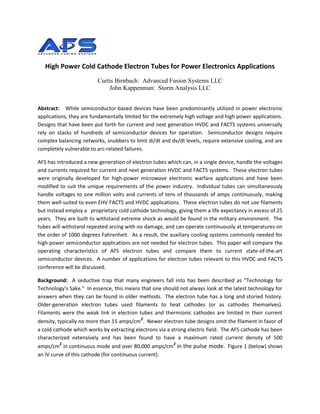
  • 1. High Power Cold Cathode Electron Tubes for Power Electronics Applications Curtis Birnbach: Advanced Fusion Systems LLC John Kappenman: Storm Analysis LLC Abstract: While semiconductor-based devices have been predominantly utilized in power electronic applications, they are fundamentally limited for the extremely high voltage and high power applications. Designs that have been put forth for current and next generation HVDC and FACTS systems universally rely on stacks of hundreds of semiconductor devices for operation. Semiconductor designs require complex balancing networks, snubbers to limit di/dt and dv/dt levels, require extensive cooling, and are completely vulnerable to arc-related failures. AFS has introduced a new generation of electron tubes which can, in a single device, handle the voltages and currents required for current and next generation HVDC and FACTS systems. These electron tubes were originally developed for high-power microwave electronic warfare applications and have been modified to suit the unique requirements of the power industry. Individual tubes can simultaneously handle voltages to one million volts and currents of tens of thousands of amps continuously, making them well-suited to even EHV FACTS and HVDC applications. These electron tubes do not use filaments but instead employ a proprietary cold cathode technology, giving them a life expectancy in excess of 25 years. They are built to withstand extreme shock as would be found in the military environment. The tubes will withstand repeated arcing with no damage, and can operate continuously at temperatures on the order of 1000 degrees Fahrenheit. As a result, the auxiliary cooling systems commonly needed for high power semiconductor applications are not needed for electron tubes. This paper will compare the operating characteristics of AFS electron tubes and compare them to current state-of-the-art semiconductor devices. A number of applications for electron tubes relevant to this HVDC and FACTS conference will be discussed. Background: A seductive trap that many engineers fall into has been described as “Technology for Technology’s Sake.” In essence, this means that one should not always look at the latest technology for answers when they can be found in older methods. The electron tube has a long and storied history. Older-generation electron tubes used filaments to heat cathodes (or as cathodes themselves). Filaments were the weak link in electron tubes and thermionic cathodes are limited in their current density, typically no more than 15 amps/cm2. Newer electron tube designs omit the filament in favor of a cold cathode which works by extracting electrons via a strong electric field. The AFS cathode has been characterized extensively and has been found to have a maximum rated current density of 500 amps/cm2 in continuous mode and over 80,000 amps/cm2 in the pulse mode. Figure 1 (below) shows an IV curve of this cathode (for continuous current).
  • 2. Figure 1: IV Curve of AFS Cathode AFS through its predecessor corporation, Hudson Research Inc., started building this class of electron tubes in 1985. The manufacturing processes have been refined and these tubes are in their fourth generation of design. A new, 250,000 square foot factory dedicated to the manufacture of these electron devices is currently under construction and demonstrates AFS’ commitment to this industry. This facility includes extensive testing capabilities that will position it as a premier manufacturing and test site for power electronics. Comparison of Electron Tubes and Semiconductor Power Devices: This section will examine the differences between semiconductors and electron tubes in high power applications. The following table highlights the primary differences and their implications. Failure Mode Semiconductor Devices Electron Tubes Arcing Fail after first arc event Highly arc resistant Thermal Sensitivity Requires elaborate cooling Can operate up to 1000° F without cooling Voltage Handling Individual devices limited to 20KV Individual devices can handle up to 1.2MV Current Handling Individual devices can handle 8KA Individual Devices can handle >1MA Circuit Complexity Very complex circuits required Very simple circuits Table 1: Basic comparison between semiconductors and electron tubes. Discussion of Failure Modes: The following discussion provides a more detailed overview is described of the failure modes and operating limitations of semiconductor devices versus the improvements available from Electron Tubes, as noted in Table 1. Arcing: The crystalline structure of semiconductor devices is a non-forgiving insulator. In operation, a semiconductor can be called on to conduct electricity at one moment and to block its flow at the next. All semiconductor materials used in power electronics exhibit the piezo-electric effect. This is the cause of a substantial number of failures and is one of the underlying fundamental limitations of semiconductors. As the following figure (Fig 2) shows, when an electric field is applied across a typical semiconductor structure, there is a discontinuity in field strength in the region of the electrodes. 2
  • 3. Figure 2. Piezo-electric failure mode of semiconductor devices This discontinuity translates directly into different amount of expansion due to the piezo-electric effect. In the areas where there are adjacent zones of differing piezo-electric expansion, the crystal is stressed in a non-uniform manner, leading to a localized mechanical failure. This manifests itself first as a crack. This causes the local electric field to increase, and when it passes the insulation standoff rating of the remaining crystalline material, an arc occurs. This carbonizes the arc path and renders the device useless. Under these stresses, the crystal essentially tears itself apart. In this case, the presence of the electrode is the underlying reason for this failure mode, due to the non- uniformity of the electric field it introduces. Even for a design case of a semiconductor device with a uniform electrode across its entire face, piezo-electric expansion stress is still an important failure mode. In the presence of a similarly uniform ground plane, such a device would be able to withstand higher voltages, but would still eventually fail when the expansion induced by the piezo-electric effect exceeds the stress modulus of the crystal. A secondary issue is that it is necessary to have electrodes to create advanced turn-on devices, unless the device is simply limited to a diode. An electron tube, on the other hand, incorporates a vacuum in a physical space as the insulator. Vacuum is inherently self-healing, so, even if an arc occurs, it rapidly dissipates and normal operation is restored. In fact, arcing is a normal condition during processing of electron tubes. Many types of tubes, such as magnetrons, klystrons and some power triodes, operate under conditions where arcs occur as a normal part of operation and are shrugged off by the tube. In electron-beam coating system power supplies, a staple manufacturing technology for the semiconductor industry, power triode electron tubes are frequently used as output devices because of their resistance to damage from the arcing that frequently occurs during this process. The fact that the semiconductor manufacturing industry needs to use tubes to get a reliable process should be an indicator of the inherent robustness of the devices. 3
  • 4. The insensitivity of electron tubes to arcing increases the reliability of a power system in several ways. Aside from eliminating failures due to transients, they also eliminate the need for elaborate snubber- type networks to suppress various types of transients that commonly occur in power systems. Reduced component count translates directly to increased mean-time-between-failures (MTBF), the main metric of reliability in electric systems. Thermal Sensitivity: It is well-known and undisputed that semiconductor devices are highly sensitive to their thermal environment. Once their temperature exceeds a critical value, about 25oC, their performance rapidly degenerates. Figure 3 (below) shows the efficiency versus temperature curve of typical semiconductor power devices. Figure 3 also demonstrates the extensive need for cooling that semiconductors require to avoid operational derating. This extreme temperature limitation usually needs to be compensated by auxiliary cooling systems and extensive valve hall structure to house and carefully regulate the semiconductors ambient environments. Figure 3: Thermal efficiency of silicon power devices When confronted by this data, it is tempting to turn to some of the more exotic semiconductors, such as silicon carbide, gallium nitride, etc., as a solution to this problem. However, this is not as simple as it seems. While silicon technology is extremely mature, and high manufacturing yields are the norm, in the exotic materials, it is difficult to grow crystals of sufficient diameter, with sufficient purity and freedom from dislocations and twinning, to achieve the same ratings and cost economies as found with silicon. Even allowing for high-yield production of devices based on these exotic materials, the piezo- electric effect will still be an important limitation due to the previously discussed single arc failure mode. In contrast, electron tubes have been demonstrated to operate from -196oC (temperature of liquid nitrogen) to 500oC with no impact on device performance. This extended operating range means that auxiliary cooling systems are usually not necessary and that even outdoor apparatus is achievable saving the costs of expensive valve hall superstructures. Voltage Handling: At the time of writing this article, the best solid state devices can handle about 20KV. This means that for a 1,000 kV system, stacks of 60 devices are required just to achieve the required voltage handling capability. These stacks also usually need to be paralleled to achieve the required current handling capacity. However, this presumes that only the highest voltage devices are used. More likely as in recently announced major HVDC expansion projects, the devices used are rated at 8KV maximum. While the specifics of these designs are not fully known, it is reasonable that given a 75% 4
  • 5. rating, to achieve the same 1,000 kV rating, over 170 devices per stack would be required for these operating voltage levels. It is important to remember that some level of device failure of any in these stacks needs to be planned for, such that a margin of normal failure can be tolerated. This means adding additional semiconductor devices into the stack (or press-pack) construction. Also in stack construction, balancing networks are required to ensure even distribution of voltage across each of the devices in a stack. Additional support circuitry in the form of snubber circuits is necessary to protect the semiconductors from sudden voltage and current surges (di/dt and dv/dt) which would lead to arcing and premature failure. The ability to provide cooling auxiliaries for heat dissipation to all these semiconductor devices while maintaining increasing voltage withstand (BIL) across the devices also adds complexity and substantial costs to the overall design, as well as additional possible failure modes. In short, these complex semiconductor device arrays increase the complexity of a design and lower its MTBF. AFS electron tubes are manufactured as single devices with service ratings up to 1.2MV. They take up substantially less space that their solid state counterparts for any power electronics in excess of 15KV overall voltage rating. In most practical high power applications, auxiliary cooling is not required for electron tubes, which further reduces complexity and modes of possible failure. Current Handling: Individual semiconductor devices, as currently used in the power electronics arena, typically have maximum ratings on the order of 4 to 5 thousand amps continuous. At least one manufacturer has reported a peak current capability of “80KA for short periods”, though it is unclear the specifics on the time withstand and how broadly that may apply for semiconductor devices. Devices must be paralleled to achieve higher current handling capacity. This is easier said than done and requires complex balancing networks to ensure even current distribution across all devices. As is the case with voltage balancing networks, the current balancing networks decrease the reliability of a system. Circuit Complexity: As discussed in the preceding two sections, when it is necessary to design for high voltages and high currents, semiconductor devices require complex support circuitry and extensive cooling, and even with this are still subject to sudden failure due to voltage or current surges. Electron tube circuits are very simple due to the single control element present. They are not affected by voltage or current surges, or high operating temperatures. Therefore in any reasonable comparison to semiconductor devices, electron tubes seem to be ideal devices for power electronic systems. Electron Tube Application Ranges: Earlier in this paper the concept of “Technology for Technology’s sake” was discussed. This concept mandates choosing the right technology for each specific task. It turns out that while it is possible to build electron tubes to operate at fairly low voltages, once they go below a certain size, it is cheaper to build and use semiconductor devices, particularly for voltages substantially below 4KV. In the intermediate range, from 4 kV to 50 kV or so, the choice of tubes or semiconductors can only be determined on a case by case basis. Over 50 kV, tubes become the technology of choice. However in all cases where robustness is required, where maintaining proper cooling is difficult, when requiring operation in high transient environments, tubes are clearly the 5
  • 6. technology of choice. Even at lower kV Operating Ranges, electron tubes can offer much higher current ratings than semi-conductor devices and applications can be now realized for such needs as fault- current limiting. At operating voltages over 250kV and given the new availability of electron tubes, semiconductor devices should be viewed as a questionable choice at best. Voltage and Current Handling Capacity: As can be seen in Figure 4, modern electron tubes can handle 4 to 5 orders of magnitude greater voltage and current than the present semiconductor devices. Unlike semiconductor devices, the overall current and voltage capacity of an electron tube rises as they get larger. This is based on two factors: the standoff voltage rises proportionally to the physical size of the tube; and the current handling capacity is based on the number of square centimeters of cathode material. The cathode is rated at a maximum of 500 Amps/cm2, but in order to assure long lifetimes, the device is typically only loaded to 250 Amps/cm2. Thus, a typical cathode, of say, 1 inch height and five inches length would have a continuous current rating in excess of 50KA. This is a fairly small cathode in this technology. In a tube rated at 500KV, with a 5 inch diameter by one foot long cathode, the continuous current rating would be 790 kA. This would equate to something like 364BVA (Billion Volt-Amperes), clearly a value that is way beyond anything likely to be encountered in practical power systems. Thus, the cathode loading is reduced and the life of the tube is substantially extended, in essence providing for extreme robustness of the electron tube device in even the largest of high voltage, high power applications. Figure 4: Electron Tubes (Red) vs. Semiconductors (Blue): Single Device Voltage vs. Current Continuous Capacity 6
  • 7. Voltage Drop / Insertion Loss: One of the most important considerations for any power switching device is its voltage drop, which is also referred to as insertion loss. Typical semiconductor junctions have a voltage drop of 0.5 to 0.7 volts in the forward conduction mode due to the ohmic drop across the semiconductor layers. This means that each junction will draw some amount of power, just to get a signal through. This current translates directly into internal heat due to I2R losses. This is substantial when you add up the losses for a couple of hundred junctions. In a cold-cathode field-emission electron tube, the loss situation is vastly different. The electron tube does not work by trying to push electrons through a crystal. These tubes just have to convince the electrons to propagate across a vacuum. The propagations of electrons in a vacuum plasma is essentially lossless, as plasmas exhibit properties akin to superconductors. Thus, the only losses are the work function loss of the electrodes. In AFS tubes, this equates to about 10 electron volts (also can be expressed as resistance of ~150 micro-ohms), which is up to ~3 orders of magnitude less than the losses of a typical semiconductor junction. Switching Loss: For many FACTS applications, increasing demands are placed on the semiconductor devices to perform multiple and rapid switching of high voltages and high currents. When a semiconductor is used for high frequency switching, switching losses during the turn-on and turn-off operation should be taken into consideration, as these losses can exceed by many times the steady- state losses of the device as previously discussed. Most semiconductor manufacturer device specifications indicate that switch turn on and turn off times increases with Power (VxI) ratings of semiconductor device. Therefore with semiconductor device switching power levels as low as ~2MVA, the semiconductor device turn-off times can be as long as 200 usec. The longer the switching time, the greater the total losses in the semiconductor device. On the other hand, Electron tubes again exhibit 3 orders or greater magnitude faster switch transition times (<100 psec) compared to semiconductor devices. Figure 5 provides a plot of voltage and current during turn-on of an electron tube device. 7
  • 8. Figure 5. Electron Tube current & voltage turn on transition [red is current, purple is voltage, green is electric field] Application Discussion: The combination of high voltage and current operating ranges of Electron Tubes combined with other superior attributes of low losses, extended thermal operating range and failure tolerance make these devices well suited for nearly all existing power electronic applications now done with semiconductor devices. In addition, the enormous expansion of operating range of the Electron Tubes also make conceivable new horizons for FACTS devices that were simply unattainable or impractical with semi-conductor devices. This includes such concepts of fault-current limiters (discussed later) as well as AC and DC solid-state circuit breakers and other feasible applications in the electric power industry that Advanced Fusion will demonstrate at future dates. In regards to all existing HVDC and FACTS systems, Advanced Fusion offers devices that can be direct replacements or alternatives to the semiconductor counterpart. Virtually any topology that can be implemented with semiconductor devices can be implemented using electron tubes. Historically, semiconductors, when first introduced, implemented tube circuits. History has come full circle with the re-introduction of electron tube technology. One other non-obvious advantage of electron tubes is that manufacture involves readily available materials and CNC type fabrication approaches. This allows for the ability to readily customize most electron tubes to meet the unique rating, configuration, and cost requirements of an application. Pulsatron & Bi-tron: The electron tube devices can be more concisely described by noting that they fit into two broad categories as a purely DC operating device or as an AC or bi-directional operating device. The DC electron tube device called the Pulsatron was originally developed in the mid-1980’s as a replacement for spark gaps in high voltage pulse modulators. It is an extremely fast (~100 picosecond) 8
  • 9. risetime cold cathode field emission triode. It has subsequently been tested in a variety of circuits and has been found to be a viable replacement for semiconductor devices in every application over 4000 volts. It has been used in pulse power supplies with output voltages up to 750 KV and 250KA. The design has been found to scale linearly. The Pulsatron™ is also an advanced turn-on and turn-off device. It can support closing mode, opening mode and all conventional CW and Pulse operating modes. The device due to the enormous capability has been likened to a thyristor on steroids. Recently, a tetrode variant has been developed to respond to the need for a bi-directional device for AC circuitry. This tube is known as the Bi-tron™, and is functionally comparable to an IGBT in many aspects, except it can be produced for operation at voltages up to 1.2 MV and current ratings in the hundreds of KA. As is the case with the Pulsatron, this tube is capable of operating in many modes including high- speed switching circuits, Class A, AB, B, C, and D amplifiers, flip-flops, Marx generators, to name a few. AFS is in the process of developing SPICE models of these tubes to facilitate other parties designing circuits using these devices. These SPICE models are expected to be available during 2011. Fault Current Limiters: The need for compact efficient Fault Current Limiters (FCL’s) in large power networks at both distribution and transmission-level voltages is well established. The US Dept. of Energy has a substantial program to foster development of such systems. This concept was originally developed for a fusion power project requirement for a DC regulator that could operate in the MegaVolt and KiloAmp (simultaneous) regime. The requirement was for a regulator which could regulate from 0 to 100% over an arbitrary time period which could be very short (μsec’s) or could be as long as several hours. The circuit is shown in Figure 6. Fig 6: DC Current Regulatorpat pend AFS is currently developing an AC version of the DC regulator that contains three cold-cathode tubes in an AC implementation of the classic 2 FET current regulator. In order to extend this circuit to allow AC operation, a second shunt circuit is added so that there is one control loop for each polarity. The series regulator element is a Bi-tron™ pat pend bi-directional tetrode and the control functions are implemented using a pair of Pulsatron cold-cathode DC triodes, one for each polarity of the sine wave. All three tubes 9
  • 10. are packaged in a single ruggedized stainless steel housing. This multi-tube assembly is known as the Faultron™. AFS has designed and is currently constructing a 10 MW continuous rated Fault Current Limiter Test Stand to support its development and production requirements. The Faultron™ equivalent circuit is shown below in Figure 7. Fig 7: AC Fault Current Regulatorpat pend Geomagnetically Induced Current Protection: The threat of Geomagnetically Induced Current (GIC) events is a well-documented threat to the power grid. NERC has categorized this threat in the “Low Frequency – High Impact” class; they don’t happen often, but when they do, the results can be catastrophic. This approach is discussed in more detail in companion paper at this conference. What is important to stress is the potential consequences from a full-on impact of a severe geomagnetic storm event: An unprotected grid can be disabled for extended periods of time. In Figure 8 (below), the Kappenman circuit is shown in Normal, Early Stage of a Fault, and Full Fault mode. Fig 8: Kappenman GIC Neutral Blocking Device 10
  • 11. HVDC to 3-Phase AC Inverters: HVDC has been widely utilized for many years in the electric power industry. While the conversion of AC to DC is very easy, the reverse process is non-trivial. AFS has a patent-pending HVDC to 3-Phase AC Inverter. This system was designed as a part of our fusion power program and was configured to provide current limiting from 1 to 100%. It will accept input voltages as high as 10MV and convert to 3-Phase AC at any standard transmission voltage. The system incorporates built-in current limiting and a dynamic phase load matching technique which balances out phase to phase differences in the line that it is connected to. A single phase of the three phase configuration is shown below in Figure 9. Fig 9. AFS HVDC Inverterpat pend: One Phase of Three Shown; Secondaries not Shown Static Compensators: The Bi-tron and Pulsatron electron tubes bring a new class of design possibilities to the electric power industry. Virtually any circuit topology that can be implemented with semiconductors can be implemented with greater simplicity and reliability when using electron tubes. Static compensation is another major FACTS power electronics area where electron tubes would have the capacity to make significant inroads. AFS electron tubes provide the ability to build Statcoms, UPFC and other related devices substantially in much larger MVA sizes than previously possible and for direct operation at all transmission voltages. The elimination of step-up transformers and many other related auxiliary systems in transmission applications will dramatically reduce the cost and size of implementing this critical system control functions. Circuit Breakers: As is the case with Statcoms and FCLs, electron tube technology will allow development of a new generation of circuit breakers for both AC as well as DC applications. Several topologies are currently under development at AFS. Future reports on details of these devices will be provided at future technical conferences. Surge Supression - Super Varistor Device & EMP/IEMI Protection: Because the Electron Tube has the inherent ability to absorb 10’s of Megajoules of energy and can also switch within 10’s of picoseconds, this device is readily suited to provide transient surge suppression for any source of transient that could occur on the network. The combination of large energy and ability to operate to EHV voltage levels 11
  • 12. makes this device especially key for EHV protection where MOV devices cannot be built to absorb the amount of energy needed particularly for long duration switching surge events. The ability to control multiple surges can even allow consideration of reduced BIL ratings to these EHV systems in expensive devices such as transformers. Another Low-frequency High Impact threat is that posed by an EMP/IEMI attack. EMP stands for Electromagnetic Pulse, and is a product of nuclear explosions. It is an expanding spherical wave of very fast risetime and long duration. Its destructive potential is well-documented. While it is necessary for an adversary to launch a nuclear attack, the wave couples to transmission lines and the like and destroys transformers and other major transmission components by overvoltage induced failures. IEMI (Intentional Electromagnetic Interference) is a technique that produces similar waveforms to EMP but from electrically-driven and chemically-driven sources. Unlike its EMP counterpart, IEMI can actually achieve substantially higher electric fields. It is not generally appreciated in the power industry of the magnitude of pulses that can be produced electrically. Electric fields in excess of 500KV/m have been reported. These fields are substantially in excess of those contemplated by MIL 188-125, the current standard for EMP Protection. While MIL 188-125 is nominally directed at high-altitude EMP effects and protection techniques, the procedures are applicable to a wide range of threats within the energy levels specified in this document. Unfortunately, this document does not contemplate substantially higher fields or other conditions which render it ineffective. It is of crucial import that the power industry recognizes the severity of this threat. Like it’s sister, GIC, this threat, while relatively low in incidence, has consequences that can rival the worst case scenarios of GIC events. AFS has previously proposed the use of its patent pending Field-Collapse™ technique that can be applied to transformers and generators of any size. This is essentially a really large Crowbar device, with switching devices with risetimes of under 100 picoseconds, voltage standoff capability of up to 1.2MV and current handling capabilities measured in the hundreds of KA. While not all transformers are vulnerable to these pulses, there are a substantial number (thousands according to Platts Energy reporting service) of transformers in the mid-voltage range which are vulnerable. Stated concisely, any transformer whose BIL rating is less than the applied field strength is vulnerable. These transients will also have steep fronts with rise times in the nanosecond range, therefore the ability of the electron tube to operate rapidly is an important aspect in assuring protection. There are several scenarios that make this a particularly troubling issue. These devices are suitable for AC and DC circuits of any voltage within the stated range. Bulkhead mount configurations are available to protect shielded facilities. These are rated to meet all transient suppression requirements. Single devices will handle the full current load in virtually all applications, as the ability to produce these devices in all distribution voltages and currents in the range of hundreds of KiloAmps are easily accommodated. Figures 10A and 10B (below) show the patent-pending devices for field collapse operation (10A) and bulkhead feedthrough (10B). 12
  • 13. Fig 10A: Field-Collapse™ EPS™ (3-Phase Artist Concept) Fig 10B: Bulkhead-mounted 4138 Bi-tron™ All of the above referenced applications provide evidence of the range of flexibility and adaptability that will be possible utilizing the electron tube technology for a broad range of FACTS and HVDC applications in the electric power sector. Who is AFS? Advanced Fusion Systems LLC is a privately-held corporation with its offices and manufacturing facility in Connecticut. Housed in a 250,000 square foot state-of-the–art manufacturing facility, AFS has dedicated a substantial portion of its efforts to bringing electron tube technology to the public utilities industry. This facility incorporates the latest advances in manufacturing drawing from many other industrial practices. In addition to manufacturing, the facility has a large test department capable of performing a wide range of tests in a multi-megawatt environment at voltages up to 1.2 MV AC & DC. This facility will have some of the largest indoor shielded test cells in the industry. 13
  • 14. Figure 11: AFS Connecticut Facility 14