SlideShare una empresa de Scribd logo
1 de 13
Descargar para leer sin conexión
AN699
  Anti-Aliasing, Analog Filters for Data Acquisition Systems

  Author:     Bonnie C. Baker                                    ANALOG VERSUS DIGITAL FILTERS
              Microchip Technology Inc.
                                                                 A system that includes an analog filter, a digital filter or
                                                                 both is shown in Figure 1. When an analog filter is
INTRODUCTION                                                     implemented, it is done prior to the analog-to-digital
                                                                 conversion. In contrast, when a digital filter is imple-
Analog filters can be found in almost every electronic
                                                                 mented, it is done after the conversion from ana-
circuit. Audio systems use them for preamplification,
                                                                 log-to-digital has occurred. It is obvious why the two
equalization, and tone control. In communication sys-
                                                                 filters are implemented at these particular points, how-
tems, filters are used for tuning in specific frequencies
                                                                 ever, the ramifications of these restrictions are not quite
and eliminating others. Digital signal processing sys-
                                                                 so obvious.
tems use filters to prevent the aliasing of out-of-band
noise and interference.
This application note investigates the design of analog
filters that reduce the influence of extraneous noise in              Analog        Analog         A/D           Digital
data acquisition systems. These types of systems pri-                 Input         Low Pass       Conversion    Filter
                                                                      Signal        Filter
marily utilize low-pass filters, digital filters or a combina-
tion of both. With the analog low-pass filter, high
frequency noise and interference can be removed from
the signal path prior to the analog-to-digital (A/D) con-
version. In this manner, the digital output code of the          FIGURE 1: The data acquisition system signal chain
conversion does not contain undesirable aliased har-             can utilize analog or digital filtering techniques or a
monic information. In contrast, a digital filter can be uti-     combination of the two.
lized to reduce in-band frequency noise by using                 There are a number of system differences when the fil-
averaging techniques.                                            tering function is provided in the digital domain rather
Although the application note is about analog filters, the       than the analog domain and the user should be aware
first section will compare the merits of an analog filter-       of these.
ing strategy versus digital filtering.                           Analog filtering can remove noise superimposed on the
Following this comparison, analog filter design param-           analog signal before it reaches the Analog-to-Digital
eters are defined. The frequency characteristics of a            Converter. In particular, this includes extraneous noise
low pass filter will also be discussed with some refer-          peaks. Digital filtering cannot eliminate these peaks
ence to specific filter designs. In the third section, low       riding on the analog signal. Consequently, noise peaks
pass filter designs will be discussed in depth.                  riding on signals near full scale have the potential to
                                                                 saturate the analog modulator of the A/D Converter.
The next portion of this application note will discuss           This is true even when the average value of the signal
techniques on how to determine the appropriate filter            is within limits.
design parameters of an anti-aliasing filter. In this sec-
tion, aliasing theory will be discussed. This will be fol-       Additionally, analog filtering is more suitable for higher
lowed by operational amplifier filter circuits. Examples         speed systems, i.e., above approximately 5kHz. In
of active and passive low pass filters will also be dis-         these types of systems, an analog filter can reduce
cussed. Finally, a 12-bit circuit design example will be         noise in the out-of-band frequency region. This, in turn,
given. All of the active analog filters discussed in this        reduces fold back signals (see the “Anti-Aliasing Filter
application note can be designed using Microchip’s Fil-          Theory” section in this application note). The task of
terLab software. FilterLab will calculate capacitor and          obtaining high resolution is placed on the A/D Con-
resistor values, as well as, determine the number of             verter. In contrast, a digital filter, by definition uses over-
poles that are required for the application. The program         sampling and averaging techniques to reduce in band
will also generate a SPICE macromodel, which can be              and out of band noise. These two processes take time.
used for spice simulations.                                      Since digital filtering occurs after the A/D conversion
                                                                 process, it can remove noise injected during the con-
                                                                 version process. Analog filtering cannot do this. Also,
                                                                 the digital filter can be made programmable far more


© 1999 Microchip Technology Inc.                                                                            DS00699B-page 1
AN699
readily than an analog filter. Depending on the digital fil-               In the case where a filter has ripple in the pass band,
ter design, this gives the user the capability of program-                 the gain of the pass band (APASS) is defined as the bot-
ming the cutoff frequency and output data rates.                           tom of the ripple. The stop band frequency, fSTOP , is
                                                                           the frequency at which a minimum attenuation is
KEY LOW PASS ANALOG FILTER                                                 reached. Although it is possible that the stop band has
DESIGN PARAMETERS                                                          a ripple, the minimum gain (ASTOP) of this ripple is
                                                                           defined at the highest peak.
A low pass analog filter can be specified with four
                                                                           As the response of the filter goes beyond the cut-off fre-
parameters as shown in Figure 2 (fCUT-OFF , fSTOP ,
                                                                           quency, it falls through the transition band to the stop
AMAX, and M).
                                                                           band region. The bandwidth of the transition band is
                                                                           determined by the filter design (Butterworth, Bessel,
                     M = Filter Order               fCUT–OFF
                                            ε                              Chebyshev, etc.) and the order (M) of the filter. The filter
                                        .......                            order is determined by the number of poles in the trans-
             APASS                                                         fer function. For instance, if a filter has three poles in its
                                                                           transfer function, it can be described as a 3rd order fil-
 Gain (dB)


                                                          fSTOP
                          AMAX                                             ter.
                                                                           Generally, the transition bandwidth will become smaller
             ASTOP                                                         when more poles are used to implement the filter
                                                                           design. This is illustrated with a Butterworth filter in
                                                                           Figure 3. Ideally, a low-pass, anti-aliasing filter should
                            Pass Band                          Stop Band   perform with a “brick wall” style of response, where the
                                                  Transition
                                                    Band
                                                                           transition band is designed to be as small as possible.
                                                                           Practically speaking, this may not be the best approach
                                 Frequency(Hz)
                                                                           for an anti-aliasing solution. With active filter design,
FIGURE 2: The key analog filter design parameters                          every two poles require an operational amplifier. For
include the –3dB cut-off frequency of the filter (fcut–off),               instance, if a 32nd order filter is designed, 16 opera-
the frequency at which a minimum gain is acceptable                        tional amplifiers, 32 capacitors and up to 64 resistors
(fstop) and the number of poles (M) implemented with                       would be required to implement the circuit. Additionally,
the filter.                                                                each amplifier would contribute offset and noise errors
                                                                           into the pass band region of the response.
The cut-off frequency (fCUT-OFF) of a low pass filter is
defined as the -3dB point for a Butterworth and Bessel
filter or the frequency at which the filter response                                                       1.0
leaves the error band for the Chebyshev.
                                                                            Amplitude Response VOUT/VIN


The frequency span from DC to the cut-off frequency is                                                                                        n=1

defined as the pass band region. The magnitude of the                                                                                     n=2
                                                                                                           0.1
response in the pass band is defined as APASS as
shown in Figure 2. The response in the pass band can                                                                  n = 16            n=4
be flat with no ripple as is when a Butterworth or Bessel
filter is designed. Conversely, a Chebyshev filter has a
                                                                                                          0.01
ripple up to the cut-off frequency. The magnitude of the                                                                            n=8
ripple error of a filter is defined as ε.                                                                               n = 32

By definition, a low pass filter passes lower frequencies
up to the cut-off frequency and attenuates the higher                                       0.001
                                                                                                 0.1                      1.0                   10
frequencies that are above the cut-off frequency. An                                                             Normalized Frequency
important parameter is the filter system gain, AMAX.
This is defined as the difference between the gain in the                  FIGURE 3: A Butterworth design is used in a low
pass band region and the gain that is achieved in the                      pass filter implementation to obtain various responses
stop band region or AMAX = APASS − ASTOP.                                  with frequency dependent on the number of poles or
                                                                           order (M) of the filter.
                                                                           Strategies on how to work around these limitations will
                                                                           be discussed in the “Anti-Aliasing Theory” section of
                                                                           this application note.


DS00699B-page 2                                                                                                        © 1999 Microchip Technology Inc.
AN699
ANALOG FILTER DESIGNS                                            The rate of attenuation in the transition band is steeper
                                                                 than Butterworth and Bessel filters. For instance, a 5th
The more popular filter designs are the Butterworth,             order Butterworth response is required if it is to meet
Bessel, and Chebyshev. Each filter design can be iden-           the transition band width of a 3rd order Chebyshev.
tified by the four parameters illustrated in Figure 2.           Although there is ringing in the pass band region with
Other filter types not discussed in this application note        this filter, the stop band is void of ringing. The step
include Inverse Chebyshev, Elliptic, and Cauer                   response (Figure 5b.) has a fair degree of overshoot
designs.                                                         and ringing.
Butterworth Filter
                                                                 Bessel Filter
The Butterworth filter is by far the most popular design
used in circuits. The transfer function of a Butterworth         Once again, the transfer function of the Bessel filter has
filter consists of all poles and no zeros and is equated         only poles and no zeros. Where the Butterworth design
to:                                                              is optimized for a maximally flat pass band response
                                                                 and the Chebyshev can be easily adjusted to minimize
 VOUT /VIN = G/(a0sn + a1sn-1 + a2sn-2... an-1s2 + ans + 1)      the transition bandwidth, the Bessel filter produces a
where G is equal to the gain of the system.                      constant time delay with respect to frequency over a
                                                                 large range of frequency. Mathematically, this relation-
Table 1 lists the denominator coefficients for a Butter-
                                                                 ship can be expressed as:
worth design. Although the order of a Butterworth filter
design theoretically can be infinite, this table only lists               C = −∆θ * ∆f
coefficients up to a 5th order filter.                           where:
 M       a0         a1         a2          a3         a4              C is a constant,
 2       1.0     1.4142136                                            θ is the phase in degrees, and
 3       1.0        2.0        2.0
                                                                      f is frequency in Hz
 4       1.0     2.6131259 3.4142136 2.6131259
 5       1.0     3.2360680 5.2360680 5.2360680 3.2360680         Alternatively, the relationship can be expressed in
                                                                 degrees per radian as:
TABLE 1: Coefficients versus filter order for Butter-
worth designs.                                                        C = −∆θ / ∆ω
As shown in Figure 4a., the frequency behavior has a             where:
maximally flat magnitude response in pass-band. The
                                                                      C is a constant,
rate of attenuation in transition band is better than
Bessel, but not as good as the Chebyshev filter. There                θ is the phase in degrees, and
is no ringing in stop band. The step response of the                  ω is in radians.
Butterworth is illustrated in Figure 5a. This filter type
                                                                 The transfer function for the Bessel filter is:
has some overshoot and ringing in the time domain, but
less than the Chebyshev.                                              VOUT/VIN = G/(a0 + a1s + a2s2+... an-1sn-1 + sn)
Chebyshev Filter                                                 The denominator coefficients for a Bessel filter are
The transfer function of the Chebyshev filter is only sim-       given in Table 3. Although the order of a Bessel filter
ilar to the Butterworth filter in that it has all poles and no   design theoretically can be infinite, this table only lists
zeros with a transfer function of:                               coefficients up to a 5th order filter.
     VOUT/VIN = G/(a0 + a1s + a2s2+... an-1sn-1 + sn)
                                                                  M        a0        a1        a2         a3        a4
Its frequency behavior has a ripple (Figure 4b.) in the
                                                                  2        3             3
pass-band that is determined by the specific placement of
                                                                  3        15        15         6
the poles in the circuit design. The magnitude of the ripple
is defined in Figure 2 as ε. In general, an increase in ripple    4       105        105       45         10
magnitude will lessen the width of the transition band.           5       945        945       420        105        15

The denominator coefficients of a 0.5dB ripple Cheby-            TABLE 3: Coefficients versus filter order for Bessel
shev design are given in Table 2. Although the order of          designs.
a Chebyshev filter design theoretically can be infinite,
                                                                 The Bessel filter has a flat magnitude response in
this table only lists coefficients up to a 5th order filter.
                                                                 pass-band (Figure 4c). Following the pass band, the
 M       a0         a1         a2          a3         a4         rate of attenuation in transition band is slower than the
 2    1.516203   1.425625
                                                                 Butterworth or Chebyshev. And finally, there is no ring-
                                                                 ing in stop band. This filter has the best step response
 3    0.715694   1.534895    1.252913
                                                                 of all the filters mentioned above, with very little over-
 4    0.379051   1.025455    1.716866   1.197386
                                                                 shoot or ringing (Figure 5c.).
 5    0.178923   0.752518    1.309575   1.937367   1.172491

TABLE 2: Coefficients versus filter order for 1/2dB
ripple Chebyshev designs.


© 1999 Microchip Technology Inc.                                                                          DS00699B-page 3
AN699

                        (a) 5th Order Butterworth Filter               (b) 5th Order Chebyshev with 0.5dB Ripple                                                                         (c) 5th Order Bessel Filter
                         10                                                                          10                                                                                 10
                          0                                                                           0                                                                                  0
                        -10                                                                         -10                                                                                -10


                                                                                                                                                                      Magnitude (dB)
       Magnitude (dB)


                                                                                   Magnitude (dB)
                        -20                                                                         -20                                                                                -20
                        -30                                                                         -30                                                                                -30
                        -40                                                                         -40                                                                                -40
                        -50                                                                         -50                                                                                -50
                        -60                                                                         -60                                                                                -60
                        -70                                                                         -70                                                                                -70

                          0.1           1            10                                               0.1           1            10                                                      0.1           1            10
                            Normalized Frequency (Hz)                                                   Normalized Frequency (Hz)                                                          Normalized Frequency (Hz)

FIGURE 4:                             The frequency responses of the more popular filters, Butterworth (a), Chebyshev (b), and Bessel (c)..
                        (a) 5th Order Butterworth Filter               (b) 5th Order Chebyshev with 0.5dB Ripple                                                                         (c) 5th Order Bessel Filter
  Amplitude (V)


                                                                        Amplitude (V)


                                                                                                                                                      Amplitude (V)
                                            Time (s)                                                            Time (s)                                                                           Time (s)

FIGURE 5:                             The step response of the 5th order filters shown in Figure 4 are illustrated here.

ANTI-ALIASING FILTER THEORY                                                                                            In both parts of this figure, the x-axis identifies the fre-
                                                                                                                       quency of the sampling system, fS. In the left portion of
A/D Converters are usually operated with a constant                                                                    Figure 6, five segments of the frequency band are iden-
sampling frequency when digitizing analog signals. By                                                                  tified. Segment N =0 spans from DC to one half of the
using a sampling frequency (fS), typically called the                                                                  sampling rate. In this bandwidth, the sampling system
Nyquist rate, all input signals with frequencies below                                                                 will reliably record the frequency content of an analog
fS/2 are reliably digitized. If there is a portion of the                                                              input signal. In the segments where N > 0, the fre-
input signal that resides in the frequency domain above                                                                quency content of the analog signal will be recorded by
fS/2, that portion will fold back into the bandwidth of                                                                the digitizing system in the bandwidth of the segment
interest with the amplitude preserved. The phenomena                                                                   N = 0. Mathematically, these higher frequencies will be
makes it impossible to discern the difference between                                                                  folded back with the following equation:
a signal from the lower frequencies (below fS/2) and                                                                                      f A LI A S E D = f I N – NfS
higher frequencies (above fS/2).
This aliasing or fold back phenomena is illustrated in
the frequency domain in Figure 6.
 a)                                                                                                                  b)
                        N=0          N=1               N=2            N=3                                 N=4                            N=0
                                                                                                                       Sampled Output
 Analog Input


                                                                                                                       Representation


                              (1)                                                                                                                                (1)
                                     (2)                                                                                                      (2)

                                                             (3)                                                                                (3)
                                                                      (4)                                                               (4)
                                                                                                    (5)                                                                            (5)


                0             fs/2     fs     3fs/2    2fs    5fs/2   3fs                  6fs/2          4fs                  0                                      fs/2                               fs
FIGURE 6: A system that is sampling an input signal at fs (a) will identify signals with frequencies below fs/2 as well as
above. Input signals below fs/2 will be reliably digitized while signals above fs/2 will be folded back (b) and appear as lower
frequencies in the digital output.


DS00699B-page 4                                                                                                                                                                           © 1999 Microchip Technology Inc.
AN699
For example, let the sampling rate, (fS), of the system
be equal to 100kHz and the frequency content of:                                                     Low Pass Filter

     fIN(1) = 41kHz
                                                                                                                                 (2)


                                                                  Analog Output
     fIN(2) = 82kHz                                                                            (1)
     fIN(3) = 219kHz
     fIN(4) = 294kHz
     fIN(5) = 347kHz
The sampled output will contain accurate amplitude
information of all of these input signals, however, four                          0                  fs/2                              fs
of them will be folded back into the frequency range
of DC to fS/2 or DC to 50kHz. By using the equation             FIGURE 7:      If the sampling system has a low pass
fOUT = |fIN - NfS|, the frequencies of the input signals        analog filter prior to the sampling mechanism, high
are transformed to:                                             frequency signals will be attenuated and not sampled.
     fOUT(1) = |41kHz - 0 x 100kHz| = 41kHz
     fOUT(2) = |82kHz - 1 x 100kHz| = 18kHz
                                                                ANALOG FILTER REALIZATION
     fOUT(3) = |219kHz - 2 x 100kHz| = 19kHz                    Traditionally, low pass filters were implemented with
     fOUT(4) = |294kHz - 3 x 100kHz| = 6kHz                     passive devices, ie. resistors and capacitors. Inductors
                                                                were added when high pass or band pass filters were
     fOUT(5) = |347kHz - 4 x 100kHz| = 53kHz
                                                                needed. At the time active filter designs were realizable,
Note that all of these signal frequencies are between           however, the cost of operational amplifiers was prohibi-
DC and fS/2 and that the amplitude information has              tive. Passive filters are still used with filter design when
been reliably retained.                                         a single pole filter is required or where the bandwidth of
This frequency folding phenomena can be eliminated              the filter operates at higher frequencies than leading
or significantly reduced by using an analog low pass fil-       edge operational amplifiers. Even with these two excep-
ter prior to the A/D Converter input. This concept is           tions, filter realization is predominately implemented
illustrated in Figure 7. In this diagram, the low pass filter   with operational amplifiers, capacitors and resistors.
attenuates the second portion of the input signal at fre-       Passive Filters
quency (2). Consequently, this signal will not be aliased
into the final sampled output. There are two regions of         Passive, low pass filters are realized with resistors and
the analog low pass filter illustrated in Figure 7. The         capacitors. The realization of single and double pole
region to the left is within the bandwidth of DC to fS/2.       low pass filters are shown in Figure 8.
The second region, which is shaded, illustrates the
transition band of the filter. Since this region is greater
                                                                                                                  20
than fS/2, signals within this frequency band will be                                                                                       fc =1/2p R2C2
                                                                                  VOUT       1
aliased into the output of the sampling system. The
                                                                                                          Gain (dB)


                                                                                         =
                                                                                  VIN      1+sRC
affects of this error can be minimized by moving the                                                                  0
                                                                                                                                            20dB/decade
corner frequency of the filter lower than fS/2 or increas-
                                                                                         R2
ing the order of the filter. In both cases, the minimum                                                        -20
                                                                                                   VOUT
gain of the filter, ASTOP , at fS/2 should less than the sig-    VIN
                                                                                              C2
nal-to-noise ratio (SNR) of the sampling system.
                                                                                                                      100   1k       10k   100k      1M
For instance, if a 12-bit A/D Converter is used, the ideal                                                                       Frequency (Hz)
SNR is 74dB. The filter should be designed so that its
gain at fSTOP is at least 74dB less than the pass band          FIGURE 8: A resistor and capacitor can be used to
gain. Assuming a 5th order filter is used in this example:      implement a passive, low pass analog filter. The input
     fCUT-OFF = 0.18fS /2 for a Butterworth Filter              and output impedance of this type of filter
     fCUT-OFF = 0.11fS /2 for a Bessel Filter                   implementation is equal to R2.
     fCUT-OFF = 0.21fS /2 for a Chebyshev Filter with           The output impedance of a passive low pass filter is rel-
                0.5dB ripple in the pass band                   atively high when compared to the active filter realiza-
     fCUT-OFF = 0.26fS /2 for a Chebyshev Filter with           tion. For instance, a 1kHz low pass filter which uses a
                1dB ripple in the pass band                     0.1µF capacitor in the design would require a 1.59kΩ
                                                                resistor to complete the implementation. This value of
                                                                resistor could create an undesirable voltage drop or
                                                                make impedance matching difficult. Consequently,
                                                                passive filters are typically used to implement a single
                                                                pole. Single pole operational amplifier filters have the
                                                                added benefit of “isolating” the high impedance of the
                                                                filter from the following circuitry.


© 1999 Microchip Technology Inc.                                                                                                    DS00699B-page 5
AN699
 a. Single pole, non-inverting active filter    b. Single pole, inverting active filter             c. Frequency response of single pole
                                                                                                          non-inverting active filter
           VOUT          1 + R 2 / R1                     VOUT         –R2 / R1
                     =                                           =
            VIN          1+sR2C2                          VIN         1+sR2C2                                      60
                                                                                                                                             fc =1/ 2π R2C2
                                                                                                                         1 + R 2 / R1


                                                                                                       Gain (dB)
                            C2                                            C2                                       40
                                                                                                                                                20dB/decade

                                                     R1
                            R2                                                                                     20
                                               VIN                       R2
   R1                                   VOUT                                              VOUT
                     MCP601                                        MCP601
                                                        VREF                                                       100        1k    10k    100k        1M
              VIN                                                                                                              Frequency (Hz)

FIGURE 9: An operational amplifier in combination with two resistors and one capacitor can be used to implement a
1st order filter. The frequency response of these active filters is equivalent to a single pole passive low pass filter.
It is very common to use a single pole, low pass, pas-                                                              Sallen-Key
sive filter at the input of a Delta-Sigma A/D Converter.
In this case, the high output impedance of the filter                                             C2
does not interfere with the conversion process.                                                    R2
                                                                               VIN
Active Filters
                                                                                            R1                          C1                           VOUT
                                                                                                                               MCP601
An active filter uses a combination of one amplifier, one to
three resistors and one to two capacitors to implement one
or two poles. The active filter offers the advantage of pro-
viding “isolation” between stages. This is possible by tak-
                                                                                                                                        R4
ing advantage of the high input impedance and low output                                                           R3
impedance of the operational amplifier. In all cases, the
order of the filter is determined by the number of capacitors
at the input and in the feedback loop of the amplifier.                     VOUT                                    K/(R1R2C1C2)
                                                                                     =
Single Pole Filter                                                            VIN         s2+s(1/R1C2+1/R2C2+1/R2C1 – K/R2C1+1/R1R2C1C2)

The frequency response of the single pole, active filter                       K = 1 + R4 /R3
is identical to a single pole passive filter. Examples of                FIGURE 10: The double pole or Sallen-Key filter
the realization of single pole active filters are shown in               implementation has a gain G = 1 + R4 / R3. If R3 is open
Figure 9.                                                                and R4 is shorted the DC gain is equal to 1 V/V.
Double Pole, Voltage Controlled Voltage Source
The Double Pole, Voltage Controlled Voltage Source is                                                                   Sallen and Key
better know as the Sallen-Key filter realization. This fil-                                        C1
ter is configured so the DC gain is positive. In the
Sallen-Key Filter realization shown in Figure 10, the DC                                               R2
                                                                                    VIN
gain is greater than one. In the realization shown in
Figure 11, the DC gain is equal to one. In both cases,                                       R1                                   MCP601
                                                                                                                                                       VOUT
                                                                                                                         C2
the order of the filters are equal to two. The poles of
these filters are determined by the resistive and capac-
itive values of R1, R2, C1 and C2.
                                                                         FIGURE 11: The double pole or Sallen-Key filter
                                                                         implementation with a DC gain is equal to 1V/V.


DS00699B-page 6                                                                                                         © 1999 Microchip Technology Inc.
AN699
Double Pole Multiple Feedback                                    Three design parameters will be used to implement
The double pole, multiple feedback realization of a 2nd          appropriate anti-aliasing filters:
order low pass filter is shown in Figure 12. This filter         1.           Cut-off frequency for filter must be 1kHz or
can also be identified as simply a Multiple Feedback                          higher.
Filter. The DC gain of this filter inverts the signal and is     2.           Filter attenuates the signal to -74dB at 10kHz.
equal to the ratio of R1 and R2. The poles are deter-            3.           The analog signal will only be filtered and not
mined by the values of R1, R3, C1, and C2.                                    gained or inverted.
                                                                 Implementation with Bessel Filter Design
                                   R2
                                           C1                    A Bessel Filter design is used in Figure 13 to imple-
                  R1    R3                                       ment the anti-aliasing filter in the system described
        VIN                                                      above. A 5th order filter that has a cut-off frequency of
                       C2                            VOUT        1kHz is required for this implementation. A combination
                                      MCP601
                                                                 of two Sallen-Key filters plus a passive low pass filter
                                                                 are designed into the circuit as shown in Figure 14.
                                                                 This filter attenuates the analog input signal 79dB from
  VOUT                       –1/R1R3C5C6                         the pass band region to 10kHz. The frequency
          =
  VIN         2
              s C2C1 + sC1 (1/R1 + 1/R2 + 1/R3) + 1/(R2R3C2C1)   response of this Bessel, 5th order filter is shown in
                                                                 Figure 13.
FIGURE 12: A double pole, multiple feedback circuit
implementation uses three resistors and two capacitors                        10                                             90

to implement a 2nd order analog filter. DC gain is equal                       0                                               0
to –R2 / R1 .
                                                                              -10                                            -90

ANTI-ALIASING FILTER DESIGN                                                   -20                                           -180
EXAMPLE


                                                                                                                                   Phase (degrees)
                                                                              -30                                           -270
                                                                  Gain (dB)
                                                                                                                    phase
In the following examples, the data acquisition system                        -40                                           -360
signal chain shown in Figure 1 will be modified as fol-                       -50                                           -450
lows. The analog signal will go directly into an active low                                                 gain
                                                                              -60                                           -540
pass filter. In this example, the bandwidth of interest of
the analog signal is DC to 1kHz. The low pass filter will                     -70                                           -630
be designed so that high frequency signals from the                                                                         -720
                                                                              -80
analog input do not pass through to the A/D Converter                           100             1,000                 10,000
in an attempt to eliminate aliasing errors. The imple-                                     Frequency (Hz)
mentation and order of this filter will be modified accord-
ing to the design parameters. Excluding the filtering            FIGURE 13: Frequency response of 5th order Bessel
function, the anti-aliasing filter will not modify the signal    design implemented in Figure 14.
further, i.e., implement a gain or invert the signal. The
low pass filter segment will be followed by a 12-bit SAR
A/D Converter. The sampling rate of the A/D Converter
will be 20kHz, making 1/2 of Nyquist equal to 10kHz.
The ideal signal-to-noise ratio of a 12-bit A/D Converter
of 74dB. This design parameter will be used when
determining the order of the anti-aliasing filter. The filter
examples discussed in this section were generated
using Microchip’s FilterLab software.


© 1999 Microchip Technology Inc.                                                                                   DS00699B-page 7
AN699

                     33nF
                                                                                             10nF
      VIN               18.2kΩ

                                                               10.5kΩ            1.96kΩ      16.2kΩ
            2.94kΩ                4.7nF
                                           MCP601
                                                                         10nF                            33µF   MCP601
                                                                                                                                  VOUT


FIGURE 14: 5th order Bessel design implemented two Sallen-Key filters and on passive filter. This filter is designed to
be an anti-aliasing filter that has a cut-off frequency of 1kHz and a stop band frequency of ~5kHz.
Implementation with Chebyshev Design                                    Although the order of this filter is less than the Bessel,
                                                                        it has a 4dB ripple in the pass band portion of the fre-
When a Chebyshev filter design is used to implement
                                                                        quency response. The combination of one Sallen-Key
the anti-aliasing filter in the system described above, a
                                                                        filter plus a passive low pass filter is used. This filter is
3rd order filter is required, as shown Figure 15.
                                                                        attenuated to -70dB at 10kHz. The frequency response
                                                                        of this Chebyshev 3rd order filter is shown in Figure 16.

                          330nF                                                      10                                              90

                                                                                      0                                                  0
  9.31kΩ       2.15kΩ      20kΩ
                                                                                     -10                                            -90
                                                                                                                          phase
VIN           68nF                 2.2nF
                                           MCP601                                    -20                                           -180
                                                        VOUT


                                                                                                                                             Phase (degrees)
                                                                                     -30                                           -270
                                                                         Gain (dB)


                                                                                     -40                                           -360
                                                                                                             gain
                                                                                     -50                                           -450
FIGURE 15: 3rd order Chebyshev design implemen-
                                                                                     -60                                           -540
ted using one Sallen-Key filter and one passive filter.
This filter is designed to be an anti-aliasing filter that has                       -70                                           -630
a cut-off frequency of 1kHz -4db ripple and a stop band                                                                            -720
                                                                                     -80
frequency of ~5kHz.                                                                    100                 1,000             10,000
                                                                                                      Frequency (Hz)

                                                                        FIGURE 16: Frequency response of 3rd                             order
                                                                        Chebyshev design implemented in Figure 15.
                                                                        This filter provides less than the ideal 74dB of dynamic
                                                                        range (AMAX), which should be taken into consider-
                                                                        ation.
                                                                        The difference between -70dB and -74dB attenuation
                                                                        in a 12-bit system will introduce little less than 1/2 LSB
                                                                        error. This occurs as a result of aliased signals from
                                                                        10kHz to 11.8KHz. Additionally, a 4dB gain error will
                                                                        occur in the pass band. This is a consequence of the
                                                                        ripple response in the pass band, as shown in
                                                                        Figure 16.


DS00699B-page 8                                                                                            © 1999 Microchip Technology Inc.
AN699

                        33nF
                                                                                    100nF
         VIN             26.1kΩ

                                                                 2.37kΩ             15.4kΩ
               2.94kΩ              10nF
                                           MCP601
                                                                                             6.8nF
                                                                                                     MCP601
                                                                                                                    VOUT


FIGURE 17: 4th order Butterworth design implemented two Sallen-Key filters. This filter is designed to be an
anti-aliasing filter that has a cut-off frequency of 1kHz and a stop band frequency of ~5kHz.
Implementation with Butterworth Design                                       10                                             90
As a final alternative, a Butterworth filter design can be                    0                                              0
used in the filter implementation of the anti-aliasing fil-
                                                                             -10                                            -90
ter, as shown in Figure 17.
                                                                             -20                              phase        -180
For this circuit implementation, a 4th order filter is used


                                                                                                                                  Phase (degrees)
with a cut-off frequency of 1kHz. Two Sallen-Key filters                     -30                                           -270


                                                                 Gain (dB)
are used. This filter attenuates the pass band signal
                                                                             -40                                           -360
80dB at 10kHz. The frequency response of this Butter-
worth 4th order filter is shown in Figure 18.                                -50                       gain                -450

The frequency response of the three filters described                        -60                                           -540
above along with several other options are summarized                        -70                                           -630
in Table 4.
                                                                             -80                                           -720
                                                                               100                1,000             10,000
                                                                                             Frequency (Hz)

                                                                 FIGURE 18: Frequency response of 4th                         order
                                                                 Butterworth design implemented in Figure 17.


 FILTER        BUTTERWORTH,               BESSEL, AMAX        CHEBYSHEV, AMAX (dB)                   CHEBYSHEV, AMAX (dB)
 ORDER,          AMAX (dB)                    (dB)            W/ RIPPLE ERROR OF                      W/ RIPPLE ERROR OF
    M                                                                 1dB                                     4dB

     3                  60                     51                                  65                         70
     4                  80                     66                                  90                         92

     5                  100                    79                              117                            122

     6                  120                    92                              142                            144

     7                  140                   104                              169                            174
TABLE 4: Theoretical frequency response at 10kHz of various filter designs versus filter order. Each filter has a
cut-off frequency of 1kHz.


© 1999 Microchip Technology Inc.                                                                              DS00699B-page 9
AN699
CONCLUSION                                                    REFERENCES
Analog filtering is a critical portion of the data acquisi-   Baker, Bonnie, “Using Operational Amplifiers for Ana-
tion system. If an analog filter is not used, signals out-    log Gain in Embedded System Design”, AN682, Micro-
side half of the sampling bandwidth of the A/D                chip Technologies, Inc.
Converter are aliased back into the signal path. Once a       Analog Filter Design, Valkenburg, M. E. Van, Oxford
signal is aliased during the digitalization process, it is    University Press.
impossible to differentiate between noise with frequen-
cies in band and out of band.                                 Active and Passive Analog Filter Design, An Introduc-
                                                              tion, Huelsman, Lawrence p., McGraw Hill, Inc.
This application note discusses techniques on how to
determine and implement the appropriate analog filter
design parameters of an anti-aliasing filter.


DS00699B-page 10                                                                     © 1999 Microchip Technology Inc.
AN699
NOTES:


© 1999 Microchip Technology Inc.   DS00699B-page 11
Note the following details of the code protection feature on PICmicro® MCUs.

•    The PICmicro family meets the specifications contained in the Microchip Data Sheet.
•    Microchip believes that its family of PICmicro microcontrollers is one of the most secure products of its kind on the market today,
     when used in the intended manner and under normal conditions.
•    There are dishonest and possibly illegal methods used to breach the code protection feature. All of these methods, to our knowl-
     edge, require using the PICmicro microcontroller in a manner outside the operating specifications contained in the data sheet.
     The person doing so may be engaged in theft of intellectual property.
•    Microchip is willing to work with the customer who is concerned about the integrity of their code.
•    Neither Microchip nor any other semiconductor manufacturer can guarantee the security of their code. Code protection does not
     mean that we are guaranteeing the product as “unbreakable”.
•    Code protection is constantly evolving. We at Microchip are committed to continuously improving the code protection features of
     our product.
If you have any further questions about this matter, please contact the local sales office nearest to you.


Information contained in this publication regarding device               Trademarks
applications and the like is intended through suggestion only
and may be superseded by updates. It is your responsibility to           The Microchip name and logo, the Microchip logo, FilterLab,
ensure that your application meets with your specifications.             KEELOQ, microID, MPLAB, PIC, PICmicro, PICMASTER,
No representation or warranty is given and no liability is               PICSTART, PRO MATE, SEEVAL and The Embedded Control
assumed by Microchip Technology Incorporated with respect                Solutions Company are registered trademarks of Microchip Tech-
to the accuracy or use of such information, or infringement of           nology Incorporated in the U.S.A. and other countries.
patents or other intellectual property rights arising from such
                                                                         dsPIC, ECONOMONITOR, FanSense, FlexROM, fuzzyLAB,
use or otherwise. Use of Microchip’s products as critical com-
                                                                         In-Circuit Serial Programming, ICSP, ICEPIC, microPort,
ponents in life support systems is not authorized except with
                                                                         Migratable Memory, MPASM, MPLIB, MPLINK, MPSIM,
express written approval by Microchip. No licenses are con-
                                                                         MXDEV, PICC, PICDEM, PICDEM.net, rfPIC, Select Mode
veyed, implicitly or otherwise, under any intellectual property
                                                                         and Total Endurance are trademarks of Microchip Technology
rights.
                                                                         Incorporated in the U.S.A.

                                                                         Serialized Quick Turn Programming (SQTP) is a service mark
                                                                         of Microchip Technology Incorporated in the U.S.A.

                                                                         All other trademarks mentioned herein are property of their
                                                                         respective companies.

                                                                         © 2002, Microchip Technology Incorporated, Printed in the
                                                                         U.S.A., All Rights Reserved.

                                                                              Printed on recycled paper.


                                                                        Microchip received QS-9000 quality system
                                                                        certification for its worldwide headquarters,
                                                                        design and wafer fabrication facilities in
                                                                        Chandler and Tempe, Arizona in July 1999. The
                                                                        Company’s quality system processes and
                                                                        procedures are QS-9000 compliant for its
                                                                        PICmicro® 8-bit MCUs, KEELOQ® code hopping
                                                                        devices, Serial EEPROMs and microperipheral
                                                                        products. In addition, Microchip’s quality
                                                                        system for the design and manufacture of
                                                                        development systems is ISO 9001 certified.


 2002 Microchip Technology Inc.
M
                               WORLDWIDE SALES AND SERVICE
AMERICAS                                ASIA/PACIFIC                                 Japan
                                                                                     Microchip Technology Japan K.K.
Corporate Office                        Australia
                                                                                     Benex S-1 6F
2355 West Chandler Blvd.                Microchip Technology Australia Pty Ltd
                                                                                     3-18-20, Shinyokohama
Chandler, AZ 85224-6199                 Suite 22, 41 Rawson Street
                                                                                     Kohoku-Ku, Yokohama-shi
Tel: 480-792-7200 Fax: 480-792-7277     Epping 2121, NSW
                                                                                     Kanagawa, 222-0033, Japan
Technical Support: 480-792-7627         Australia
Web Address: http://www.microchip.com   Tel: 61-2-9868-6733 Fax: 61-2-9868-6755      Tel: 81-45-471- 6166 Fax: 81-45-471-6122
Rocky Mountain                          China - Beijing                              Korea
2355 West Chandler Blvd.                Microchip Technology Consulting (Shanghai)   Microchip Technology Korea
Chandler, AZ 85224-6199                 Co., Ltd., Beijing Liaison Office            168-1, Youngbo Bldg. 3 Floor
Tel: 480-792-7966 Fax: 480-792-7456     Unit 915                                     Samsung-Dong, Kangnam-Ku
                                        Bei Hai Wan Tai Bldg.                        Seoul, Korea 135-882
Atlanta                                 No. 6 Chaoyangmen Beidajie                   Tel: 82-2-554-7200 Fax: 82-2-558-5934
500 Sugar Mill Road, Suite 200B         Beijing, 100027, No. China                   Singapore
Atlanta, GA 30350                       Tel: 86-10-85282100 Fax: 86-10-85282104      Microchip Technology Singapore Pte Ltd.
Tel: 770-640-0034 Fax: 770-640-0307                                                  200 Middle Road
                                        China - Chengdu
Boston                                                                               #07-02 Prime Centre
                                        Microchip Technology Consulting (Shanghai)
2 Lan Drive, Suite 120                                                               Singapore, 188980
                                        Co., Ltd., Chengdu Liaison Office
Westford, MA 01886                                                                   Tel: 65-334-8870 Fax: 65-334-8850
                                        Rm. 2401, 24th Floor,
Tel: 978-692-3848 Fax: 978-692-3821                                                  Taiwan
                                        Ming Xing Financial Tower
Chicago                                 No. 88 TIDU Street                           Microchip Technology Taiwan
333 Pierce Road, Suite 180              Chengdu 610016, China                        11F-3, No. 207
Itasca, IL 60143                        Tel: 86-28-6766200 Fax: 86-28-6766599        Tung Hua North Road
Tel: 630-285-0071 Fax: 630-285-0075                                                  Taipei, 105, Taiwan
                                        China - Fuzhou
Dallas                                                                               Tel: 886-2-2717-7175 Fax: 886-2-2545-0139
                                        Microchip Technology Consulting (Shanghai)
4570 Westgrove Drive, Suite 160         Co., Ltd., Fuzhou Liaison Office
Addison, TX 75001                       Unit 28F, World Trade Plaza
Tel: 972-818-7423 Fax: 972-818-2924                                                  EUROPE
                                        No. 71 Wusi Road
Detroit                                 Fuzhou 350001, China                         Denmark
Tri-Atria Office Building               Tel: 86-591-7503506 Fax: 86-591-7503521      Microchip Technology Nordic ApS
32255 Northwestern Highway, Suite 190   China - Shanghai                             Regus Business Centre
Farmington Hills, MI 48334              Microchip Technology Consulting (Shanghai)   Lautrup hoj 1-3
Tel: 248-538-2250 Fax: 248-538-2260     Co., Ltd.                                    Ballerup DK-2750 Denmark
Kokomo                                  Room 701, Bldg. B                            Tel: 45 4420 9895 Fax: 45 4420 9910
2767 S. Albright Road                   Far East International Plaza                 France
Kokomo, Indiana 46902                   No. 317 Xian Xia Road                        Microchip Technology SARL
Tel: 765-864-8360 Fax: 765-864-8387     Shanghai, 200051                             Parc d’Activite du Moulin de Massy
Los Angeles                             Tel: 86-21-6275-5700 Fax: 86-21-6275-5060    43 Rue du Saule Trapu
18201 Von Karman, Suite 1090            China - Shenzhen                             Batiment A - ler Etage
Irvine, CA 92612                                                                     91300 Massy, France
                                        Microchip Technology Consulting (Shanghai)
Tel: 949-263-1888 Fax: 949-263-1338                                                  Tel: 33-1-69-53-63-20 Fax: 33-1-69-30-90-79
                                        Co., Ltd., Shenzhen Liaison Office
New York                                Rm. 1315, 13/F, Shenzhen Kerry Centre,       Germany
150 Motor Parkway, Suite 202            Renminnan Lu                                 Microchip Technology GmbH
Hauppauge, NY 11788                     Shenzhen 518001, China                       Gustav-Heinemann Ring 125
Tel: 631-273-5305 Fax: 631-273-5335     Tel: 86-755-2350361 Fax: 86-755-2366086      D-81739 Munich, Germany
                                                                                     Tel: 49-89-627-144 0 Fax: 49-89-627-144-44
San Jose                                Hong Kong
Microchip Technology Inc.               Microchip Technology Hongkong Ltd.           Italy
2107 North First Street, Suite 590      Unit 901-6, Tower 2, Metroplaza              Microchip Technology SRL
San Jose, CA 95131                      223 Hing Fong Road                           Centro Direzionale Colleoni
Tel: 408-436-7950 Fax: 408-436-7955     Kwai Fong, N.T., Hong Kong                   Palazzo Taurus 1 V. Le Colleoni 1
                                        Tel: 852-2401-1200 Fax: 852-2401-3431        20041 Agrate Brianza
Toronto
                                                                                     Milan, Italy
6285 Northam Drive, Suite 108           India                                        Tel: 39-039-65791-1 Fax: 39-039-6899883
Mississauga, Ontario L4V 1X5, Canada    Microchip Technology Inc.
Tel: 905-673-0699 Fax: 905-673-6509     India Liaison Office                         United Kingdom
                                        Divyasree Chambers                           Arizona Microchip Technology Ltd.
                                        1 Floor, Wing A (A3/A4)                      505 Eskdale Road
                                        No. 11, O’Shaugnessey Road                   Winnersh Triangle
                                        Bangalore, 560 025, India                    Wokingham
                                        Tel: 91-80-2290061 Fax: 91-80-2290062        Berkshire, England RG41 5TU
                                                                                     Tel: 44 118 921 5869 Fax: 44-118 921-5820

                                                                                                                           01/18/02


                                                                                              2002 Microchip Technology Inc.

Más contenido relacionado

La actualidad más candente

Digital signal processing By Er. Swapnil Kaware
Digital signal processing By Er. Swapnil KawareDigital signal processing By Er. Swapnil Kaware
Digital signal processing By Er. Swapnil KawareProf. Swapnil V. Kaware
 
Active Filter Design Using PSpice
Active Filter Design Using PSpiceActive Filter Design Using PSpice
Active Filter Design Using PSpiceTsuyoshi Horigome
 
Design of FIR Filters
Design of FIR FiltersDesign of FIR Filters
Design of FIR FiltersAranya Sarkar
 
Design of FIR filters
Design of FIR filtersDesign of FIR filters
Design of FIR filtersop205
 
Butterworth filter design
Butterworth filter designButterworth filter design
Butterworth filter designSushant Shankar
 
Digital Signal Processing Summary
Digital Signal Processing SummaryDigital Signal Processing Summary
Digital Signal Processing Summaryop205
 
An Gt123 A Electronic Step Attenuator For Microwave Signal Generators
An Gt123 A Electronic Step Attenuator For Microwave Signal GeneratorsAn Gt123 A Electronic Step Attenuator For Microwave Signal Generators
An Gt123 A Electronic Step Attenuator For Microwave Signal Generatorscf_home
 
Dss
Dss Dss
Dss nil65
 
design of sampling filter
design of sampling filter design of sampling filter
design of sampling filter Anuj Arora
 
PHOENIX AUDIO TECHNOLOGIES - A large Audio Signal Algorithm Portfolio
PHOENIX AUDIO TECHNOLOGIES  - A large Audio Signal Algorithm PortfolioPHOENIX AUDIO TECHNOLOGIES  - A large Audio Signal Algorithm Portfolio
PHOENIX AUDIO TECHNOLOGIES - A large Audio Signal Algorithm PortfolioHTCS LLC
 
Fir and iir filter_design
Fir and iir filter_designFir and iir filter_design
Fir and iir filter_designshrinivasgnaik
 
Understanding the FM Slide Chirp Advantages in Hydroacoustics for Fisheries A...
Understanding the FM Slide Chirp Advantages in Hydroacoustics for Fisheries A...Understanding the FM Slide Chirp Advantages in Hydroacoustics for Fisheries A...
Understanding the FM Slide Chirp Advantages in Hydroacoustics for Fisheries A...HTI Hydroacoustic Technology, Inc.
 
Synchronous Time / Frequency Domain Measurements Using a Digital Oscilloscope...
Synchronous Time / Frequency Domain Measurements Using a Digital Oscilloscope...Synchronous Time / Frequency Domain Measurements Using a Digital Oscilloscope...
Synchronous Time / Frequency Domain Measurements Using a Digital Oscilloscope...Rohde & Schwarz North America
 
Basics of digital filters
Basics of digital filtersBasics of digital filters
Basics of digital filtersSmile Hossain
 
Op amp applications filters cw final (2)
Op amp applications filters cw final (2)Op amp applications filters cw final (2)
Op amp applications filters cw final (2)JUNAID SK
 

La actualidad más candente (20)

Digital signal processing By Er. Swapnil Kaware
Digital signal processing By Er. Swapnil KawareDigital signal processing By Er. Swapnil Kaware
Digital signal processing By Er. Swapnil Kaware
 
Dsp lecture vol 6 design of fir
Dsp lecture vol 6 design of firDsp lecture vol 6 design of fir
Dsp lecture vol 6 design of fir
 
Digital Filters Part 1
Digital Filters Part 1Digital Filters Part 1
Digital Filters Part 1
 
Active Filter Design Using PSpice
Active Filter Design Using PSpiceActive Filter Design Using PSpice
Active Filter Design Using PSpice
 
Design of FIR Filters
Design of FIR FiltersDesign of FIR Filters
Design of FIR Filters
 
Digital Filters Part 2
Digital Filters Part 2Digital Filters Part 2
Digital Filters Part 2
 
Design of FIR filters
Design of FIR filtersDesign of FIR filters
Design of FIR filters
 
Butterworth filter design
Butterworth filter designButterworth filter design
Butterworth filter design
 
Digital Signal Processing Summary
Digital Signal Processing SummaryDigital Signal Processing Summary
Digital Signal Processing Summary
 
An Gt123 A Electronic Step Attenuator For Microwave Signal Generators
An Gt123 A Electronic Step Attenuator For Microwave Signal GeneratorsAn Gt123 A Electronic Step Attenuator For Microwave Signal Generators
An Gt123 A Electronic Step Attenuator For Microwave Signal Generators
 
Fir filter_utkarsh_kulshrestha
Fir filter_utkarsh_kulshresthaFir filter_utkarsh_kulshrestha
Fir filter_utkarsh_kulshrestha
 
Dss
Dss Dss
Dss
 
design of sampling filter
design of sampling filter design of sampling filter
design of sampling filter
 
PHOENIX AUDIO TECHNOLOGIES - A large Audio Signal Algorithm Portfolio
PHOENIX AUDIO TECHNOLOGIES  - A large Audio Signal Algorithm PortfolioPHOENIX AUDIO TECHNOLOGIES  - A large Audio Signal Algorithm Portfolio
PHOENIX AUDIO TECHNOLOGIES - A large Audio Signal Algorithm Portfolio
 
Fir and iir filter_design
Fir and iir filter_designFir and iir filter_design
Fir and iir filter_design
 
Understanding the FM Slide Chirp Advantages in Hydroacoustics for Fisheries A...
Understanding the FM Slide Chirp Advantages in Hydroacoustics for Fisheries A...Understanding the FM Slide Chirp Advantages in Hydroacoustics for Fisheries A...
Understanding the FM Slide Chirp Advantages in Hydroacoustics for Fisheries A...
 
Synchronous Time / Frequency Domain Measurements Using a Digital Oscilloscope...
Synchronous Time / Frequency Domain Measurements Using a Digital Oscilloscope...Synchronous Time / Frequency Domain Measurements Using a Digital Oscilloscope...
Synchronous Time / Frequency Domain Measurements Using a Digital Oscilloscope...
 
Basics of digital filters
Basics of digital filtersBasics of digital filters
Basics of digital filters
 
Design of Filters PPT
Design of Filters PPTDesign of Filters PPT
Design of Filters PPT
 
Op amp applications filters cw final (2)
Op amp applications filters cw final (2)Op amp applications filters cw final (2)
Op amp applications filters cw final (2)
 

Destacado

How a-video-is-crowdsourced-infographic
How a-video-is-crowdsourced-infographicHow a-video-is-crowdsourced-infographic
How a-video-is-crowdsourced-infographicdailycrowdsource
 
Curso de física básica moyses nussenzveig
Curso de física básica   moyses nussenzveigCurso de física básica   moyses nussenzveig
Curso de física básica moyses nussenzveigRafaelrpa
 
Treatmentsformenopause
TreatmentsformenopauseTreatmentsformenopause
Treatmentsformenopausekidneystones
 
Naturaltreatmentforadult adhd
Naturaltreatmentforadult adhdNaturaltreatmentforadult adhd
Naturaltreatmentforadult adhdkidneystones
 
Target Audience Questionnaire results
Target Audience Questionnaire resultsTarget Audience Questionnaire results
Target Audience Questionnaire resultsAlexFletcher_64
 

Destacado (6)

How a-video-is-crowdsourced-infographic
How a-video-is-crowdsourced-infographicHow a-video-is-crowdsourced-infographic
How a-video-is-crowdsourced-infographic
 
Curso de física básica moyses nussenzveig
Curso de física básica   moyses nussenzveigCurso de física básica   moyses nussenzveig
Curso de física básica moyses nussenzveig
 
Kidneystones
KidneystonesKidneystones
Kidneystones
 
Treatmentsformenopause
TreatmentsformenopauseTreatmentsformenopause
Treatmentsformenopause
 
Naturaltreatmentforadult adhd
Naturaltreatmentforadult adhdNaturaltreatmentforadult adhd
Naturaltreatmentforadult adhd
 
Target Audience Questionnaire results
Target Audience Questionnaire resultsTarget Audience Questionnaire results
Target Audience Questionnaire results
 

Similar a 00699b

Filter (signal processing)
Filter (signal processing)Filter (signal processing)
Filter (signal processing)RSARANYADEVI
 
Discrete time signal processing unit-2
Discrete time signal processing unit-2Discrete time signal processing unit-2
Discrete time signal processing unit-2selvalakshmi24
 
Your Ultimate Guide to Designing Analog Filters - Welcome to OXELTECH.pdf
Your Ultimate Guide to Designing Analog Filters - Welcome to OXELTECH.pdfYour Ultimate Guide to Designing Analog Filters - Welcome to OXELTECH.pdf
Your Ultimate Guide to Designing Analog Filters - Welcome to OXELTECH.pdfaud Scarlet
 
Types Of Window Being Used For The Selected Granule
Types Of Window Being Used For The Selected GranuleTypes Of Window Being Used For The Selected Granule
Types Of Window Being Used For The Selected GranuleLeslie Lee
 
Adaptive Digital Filter Design for Linear Noise Cancellation Using Neural Net...
Adaptive Digital Filter Design for Linear Noise Cancellation Using Neural Net...Adaptive Digital Filter Design for Linear Noise Cancellation Using Neural Net...
Adaptive Digital Filter Design for Linear Noise Cancellation Using Neural Net...iosrjce
 
DIGITAL FILTERS/SIGNERS types and uses.docx
DIGITAL FILTERS/SIGNERS types and uses.docxDIGITAL FILTERS/SIGNERS types and uses.docx
DIGITAL FILTERS/SIGNERS types and uses.docxgreatmike3
 
Mitigation of Noise in OFDM Based Plc System Using Filter Kernel Design
Mitigation of Noise in OFDM Based Plc System Using Filter Kernel DesignMitigation of Noise in OFDM Based Plc System Using Filter Kernel Design
Mitigation of Noise in OFDM Based Plc System Using Filter Kernel DesignIJERA Editor
 
Design and Implementation of Polyphase based Subband Adaptive Structure for N...
Design and Implementation of Polyphase based Subband Adaptive Structure for N...Design and Implementation of Polyphase based Subband Adaptive Structure for N...
Design and Implementation of Polyphase based Subband Adaptive Structure for N...Pratik Ghotkar
 
Implementation Adaptive Noise Canceler
Implementation Adaptive Noise Canceler Implementation Adaptive Noise Canceler
Implementation Adaptive Noise Canceler Akshatha suresh
 
Design of a microstrip bandpass filter
Design of a microstrip bandpass filter Design of a microstrip bandpass filter
Design of a microstrip bandpass filter Tauseef khan
 
Vibration signal filtering
Vibration signal filtering Vibration signal filtering
Vibration signal filtering JackieFAbraham
 
Digital Implementation of Costas Loop with Carrier Recovery
Digital Implementation of Costas Loop with Carrier RecoveryDigital Implementation of Costas Loop with Carrier Recovery
Digital Implementation of Costas Loop with Carrier RecoveryIJERD Editor
 
Ijarcet vol-2-issue-3-861-866
Ijarcet vol-2-issue-3-861-866Ijarcet vol-2-issue-3-861-866
Ijarcet vol-2-issue-3-861-866Editor IJARCET
 
Echo Cancellation Algorithms using Adaptive Filters: A Comparative Study
Echo Cancellation Algorithms using Adaptive Filters: A Comparative StudyEcho Cancellation Algorithms using Adaptive Filters: A Comparative Study
Echo Cancellation Algorithms using Adaptive Filters: A Comparative Studyidescitation
 
Simulation of Adaptive Noise Canceller for an ECG signal Analysis
Simulation of Adaptive Noise Canceller for an ECG signal AnalysisSimulation of Adaptive Noise Canceller for an ECG signal Analysis
Simulation of Adaptive Noise Canceller for an ECG signal AnalysisIDES Editor
 

Similar a 00699b (20)

Filter (signal processing)
Filter (signal processing)Filter (signal processing)
Filter (signal processing)
 
Discrete time signal processing unit-2
Discrete time signal processing unit-2Discrete time signal processing unit-2
Discrete time signal processing unit-2
 
Your Ultimate Guide to Designing Analog Filters - Welcome to OXELTECH.pdf
Your Ultimate Guide to Designing Analog Filters - Welcome to OXELTECH.pdfYour Ultimate Guide to Designing Analog Filters - Welcome to OXELTECH.pdf
Your Ultimate Guide to Designing Analog Filters - Welcome to OXELTECH.pdf
 
Types Of Window Being Used For The Selected Granule
Types Of Window Being Used For The Selected GranuleTypes Of Window Being Used For The Selected Granule
Types Of Window Being Used For The Selected Granule
 
Z4301132136
Z4301132136Z4301132136
Z4301132136
 
Adaptive Digital Filter Design for Linear Noise Cancellation Using Neural Net...
Adaptive Digital Filter Design for Linear Noise Cancellation Using Neural Net...Adaptive Digital Filter Design for Linear Noise Cancellation Using Neural Net...
Adaptive Digital Filter Design for Linear Noise Cancellation Using Neural Net...
 
D017632228
D017632228D017632228
D017632228
 
DIGITAL FILTERS/SIGNERS types and uses.docx
DIGITAL FILTERS/SIGNERS types and uses.docxDIGITAL FILTERS/SIGNERS types and uses.docx
DIGITAL FILTERS/SIGNERS types and uses.docx
 
Mitigation of Noise in OFDM Based Plc System Using Filter Kernel Design
Mitigation of Noise in OFDM Based Plc System Using Filter Kernel DesignMitigation of Noise in OFDM Based Plc System Using Filter Kernel Design
Mitigation of Noise in OFDM Based Plc System Using Filter Kernel Design
 
Design and Implementation of Polyphase based Subband Adaptive Structure for N...
Design and Implementation of Polyphase based Subband Adaptive Structure for N...Design and Implementation of Polyphase based Subband Adaptive Structure for N...
Design and Implementation of Polyphase based Subband Adaptive Structure for N...
 
Implementation Adaptive Noise Canceler
Implementation Adaptive Noise Canceler Implementation Adaptive Noise Canceler
Implementation Adaptive Noise Canceler
 
Design of a microstrip bandpass filter
Design of a microstrip bandpass filter Design of a microstrip bandpass filter
Design of a microstrip bandpass filter
 
Vibration signal filtering
Vibration signal filtering Vibration signal filtering
Vibration signal filtering
 
Digital Implementation of Costas Loop with Carrier Recovery
Digital Implementation of Costas Loop with Carrier RecoveryDigital Implementation of Costas Loop with Carrier Recovery
Digital Implementation of Costas Loop with Carrier Recovery
 
Ijarcet vol-2-issue-3-861-866
Ijarcet vol-2-issue-3-861-866Ijarcet vol-2-issue-3-861-866
Ijarcet vol-2-issue-3-861-866
 
C010431520
C010431520C010431520
C010431520
 
Echo Cancellation Algorithms using Adaptive Filters: A Comparative Study
Echo Cancellation Algorithms using Adaptive Filters: A Comparative StudyEcho Cancellation Algorithms using Adaptive Filters: A Comparative Study
Echo Cancellation Algorithms using Adaptive Filters: A Comparative Study
 
Analog term paper
Analog term paperAnalog term paper
Analog term paper
 
Simulation of Adaptive Noise Canceller for an ECG signal Analysis
Simulation of Adaptive Noise Canceller for an ECG signal AnalysisSimulation of Adaptive Noise Canceller for an ECG signal Analysis
Simulation of Adaptive Noise Canceller for an ECG signal Analysis
 
Pulse Shaping FIR Filter for WCDMA
Pulse Shaping FIR Filter for WCDMAPulse Shaping FIR Filter for WCDMA
Pulse Shaping FIR Filter for WCDMA
 

Último

Contemporary philippine arts from the regions_PPT_Module_12 [Autosaved] (1).pptx
Contemporary philippine arts from the regions_PPT_Module_12 [Autosaved] (1).pptxContemporary philippine arts from the regions_PPT_Module_12 [Autosaved] (1).pptx
Contemporary philippine arts from the regions_PPT_Module_12 [Autosaved] (1).pptxRoyAbrique
 
Introduction to AI in Higher Education_draft.pptx
Introduction to AI in Higher Education_draft.pptxIntroduction to AI in Higher Education_draft.pptx
Introduction to AI in Higher Education_draft.pptxpboyjonauth
 
Activity 01 - Artificial Culture (1).pdf
Activity 01 - Artificial Culture (1).pdfActivity 01 - Artificial Culture (1).pdf
Activity 01 - Artificial Culture (1).pdfciinovamais
 
SOCIAL AND HISTORICAL CONTEXT - LFTVD.pptx
SOCIAL AND HISTORICAL CONTEXT - LFTVD.pptxSOCIAL AND HISTORICAL CONTEXT - LFTVD.pptx
SOCIAL AND HISTORICAL CONTEXT - LFTVD.pptxiammrhaywood
 
How to Make a Pirate ship Primary Education.pptx
How to Make a Pirate ship Primary Education.pptxHow to Make a Pirate ship Primary Education.pptx
How to Make a Pirate ship Primary Education.pptxmanuelaromero2013
 
Employee wellbeing at the workplace.pptx
Employee wellbeing at the workplace.pptxEmployee wellbeing at the workplace.pptx
Employee wellbeing at the workplace.pptxNirmalaLoungPoorunde1
 
Web & Social Media Analytics Previous Year Question Paper.pdf
Web & Social Media Analytics Previous Year Question Paper.pdfWeb & Social Media Analytics Previous Year Question Paper.pdf
Web & Social Media Analytics Previous Year Question Paper.pdfJayanti Pande
 
Q4-W6-Restating Informational Text Grade 3
Q4-W6-Restating Informational Text Grade 3Q4-W6-Restating Informational Text Grade 3
Q4-W6-Restating Informational Text Grade 3JemimahLaneBuaron
 
A Critique of the Proposed National Education Policy Reform
A Critique of the Proposed National Education Policy ReformA Critique of the Proposed National Education Policy Reform
A Critique of the Proposed National Education Policy ReformChameera Dedduwage
 
Mastering the Unannounced Regulatory Inspection
Mastering the Unannounced Regulatory InspectionMastering the Unannounced Regulatory Inspection
Mastering the Unannounced Regulatory InspectionSafetyChain Software
 
1029 - Danh muc Sach Giao Khoa 10 . pdf
1029 -  Danh muc Sach Giao Khoa 10 . pdf1029 -  Danh muc Sach Giao Khoa 10 . pdf
1029 - Danh muc Sach Giao Khoa 10 . pdfQucHHunhnh
 
Presentation by Andreas Schleicher Tackling the School Absenteeism Crisis 30 ...
Presentation by Andreas Schleicher Tackling the School Absenteeism Crisis 30 ...Presentation by Andreas Schleicher Tackling the School Absenteeism Crisis 30 ...
Presentation by Andreas Schleicher Tackling the School Absenteeism Crisis 30 ...EduSkills OECD
 
Grant Readiness 101 TechSoup and Remy Consulting
Grant Readiness 101 TechSoup and Remy ConsultingGrant Readiness 101 TechSoup and Remy Consulting
Grant Readiness 101 TechSoup and Remy ConsultingTechSoup
 
Accessible design: Minimum effort, maximum impact
Accessible design: Minimum effort, maximum impactAccessible design: Minimum effort, maximum impact
Accessible design: Minimum effort, maximum impactdawncurless
 
microwave assisted reaction. General introduction
microwave assisted reaction. General introductionmicrowave assisted reaction. General introduction
microwave assisted reaction. General introductionMaksud Ahmed
 
Sanyam Choudhary Chemistry practical.pdf
Sanyam Choudhary Chemistry practical.pdfSanyam Choudhary Chemistry practical.pdf
Sanyam Choudhary Chemistry practical.pdfsanyamsingh5019
 

Último (20)

Contemporary philippine arts from the regions_PPT_Module_12 [Autosaved] (1).pptx
Contemporary philippine arts from the regions_PPT_Module_12 [Autosaved] (1).pptxContemporary philippine arts from the regions_PPT_Module_12 [Autosaved] (1).pptx
Contemporary philippine arts from the regions_PPT_Module_12 [Autosaved] (1).pptx
 
Código Creativo y Arte de Software | Unidad 1
Código Creativo y Arte de Software | Unidad 1Código Creativo y Arte de Software | Unidad 1
Código Creativo y Arte de Software | Unidad 1
 
Introduction to AI in Higher Education_draft.pptx
Introduction to AI in Higher Education_draft.pptxIntroduction to AI in Higher Education_draft.pptx
Introduction to AI in Higher Education_draft.pptx
 
Activity 01 - Artificial Culture (1).pdf
Activity 01 - Artificial Culture (1).pdfActivity 01 - Artificial Culture (1).pdf
Activity 01 - Artificial Culture (1).pdf
 
SOCIAL AND HISTORICAL CONTEXT - LFTVD.pptx
SOCIAL AND HISTORICAL CONTEXT - LFTVD.pptxSOCIAL AND HISTORICAL CONTEXT - LFTVD.pptx
SOCIAL AND HISTORICAL CONTEXT - LFTVD.pptx
 
How to Make a Pirate ship Primary Education.pptx
How to Make a Pirate ship Primary Education.pptxHow to Make a Pirate ship Primary Education.pptx
How to Make a Pirate ship Primary Education.pptx
 
Mattingly "AI & Prompt Design: Structured Data, Assistants, & RAG"
Mattingly "AI & Prompt Design: Structured Data, Assistants, & RAG"Mattingly "AI & Prompt Design: Structured Data, Assistants, & RAG"
Mattingly "AI & Prompt Design: Structured Data, Assistants, & RAG"
 
Employee wellbeing at the workplace.pptx
Employee wellbeing at the workplace.pptxEmployee wellbeing at the workplace.pptx
Employee wellbeing at the workplace.pptx
 
Web & Social Media Analytics Previous Year Question Paper.pdf
Web & Social Media Analytics Previous Year Question Paper.pdfWeb & Social Media Analytics Previous Year Question Paper.pdf
Web & Social Media Analytics Previous Year Question Paper.pdf
 
Q4-W6-Restating Informational Text Grade 3
Q4-W6-Restating Informational Text Grade 3Q4-W6-Restating Informational Text Grade 3
Q4-W6-Restating Informational Text Grade 3
 
Mattingly "AI & Prompt Design: The Basics of Prompt Design"
Mattingly "AI & Prompt Design: The Basics of Prompt Design"Mattingly "AI & Prompt Design: The Basics of Prompt Design"
Mattingly "AI & Prompt Design: The Basics of Prompt Design"
 
A Critique of the Proposed National Education Policy Reform
A Critique of the Proposed National Education Policy ReformA Critique of the Proposed National Education Policy Reform
A Critique of the Proposed National Education Policy Reform
 
Mastering the Unannounced Regulatory Inspection
Mastering the Unannounced Regulatory InspectionMastering the Unannounced Regulatory Inspection
Mastering the Unannounced Regulatory Inspection
 
1029 - Danh muc Sach Giao Khoa 10 . pdf
1029 -  Danh muc Sach Giao Khoa 10 . pdf1029 -  Danh muc Sach Giao Khoa 10 . pdf
1029 - Danh muc Sach Giao Khoa 10 . pdf
 
Staff of Color (SOC) Retention Efforts DDSD
Staff of Color (SOC) Retention Efforts DDSDStaff of Color (SOC) Retention Efforts DDSD
Staff of Color (SOC) Retention Efforts DDSD
 
Presentation by Andreas Schleicher Tackling the School Absenteeism Crisis 30 ...
Presentation by Andreas Schleicher Tackling the School Absenteeism Crisis 30 ...Presentation by Andreas Schleicher Tackling the School Absenteeism Crisis 30 ...
Presentation by Andreas Schleicher Tackling the School Absenteeism Crisis 30 ...
 
Grant Readiness 101 TechSoup and Remy Consulting
Grant Readiness 101 TechSoup and Remy ConsultingGrant Readiness 101 TechSoup and Remy Consulting
Grant Readiness 101 TechSoup and Remy Consulting
 
Accessible design: Minimum effort, maximum impact
Accessible design: Minimum effort, maximum impactAccessible design: Minimum effort, maximum impact
Accessible design: Minimum effort, maximum impact
 
microwave assisted reaction. General introduction
microwave assisted reaction. General introductionmicrowave assisted reaction. General introduction
microwave assisted reaction. General introduction
 
Sanyam Choudhary Chemistry practical.pdf
Sanyam Choudhary Chemistry practical.pdfSanyam Choudhary Chemistry practical.pdf
Sanyam Choudhary Chemistry practical.pdf
 

00699b

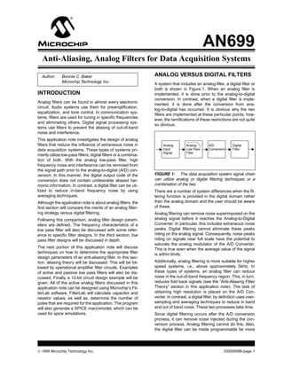
  • 1. AN699 Anti-Aliasing, Analog Filters for Data Acquisition Systems Author: Bonnie C. Baker ANALOG VERSUS DIGITAL FILTERS Microchip Technology Inc. A system that includes an analog filter, a digital filter or both is shown in Figure 1. When an analog filter is INTRODUCTION implemented, it is done prior to the analog-to-digital conversion. In contrast, when a digital filter is imple- Analog filters can be found in almost every electronic mented, it is done after the conversion from ana- circuit. Audio systems use them for preamplification, log-to-digital has occurred. It is obvious why the two equalization, and tone control. In communication sys- filters are implemented at these particular points, how- tems, filters are used for tuning in specific frequencies ever, the ramifications of these restrictions are not quite and eliminating others. Digital signal processing sys- so obvious. tems use filters to prevent the aliasing of out-of-band noise and interference. This application note investigates the design of analog filters that reduce the influence of extraneous noise in Analog Analog A/D Digital data acquisition systems. These types of systems pri- Input Low Pass Conversion Filter Signal Filter marily utilize low-pass filters, digital filters or a combina- tion of both. With the analog low-pass filter, high frequency noise and interference can be removed from the signal path prior to the analog-to-digital (A/D) con- version. In this manner, the digital output code of the FIGURE 1: The data acquisition system signal chain conversion does not contain undesirable aliased har- can utilize analog or digital filtering techniques or a monic information. In contrast, a digital filter can be uti- combination of the two. lized to reduce in-band frequency noise by using There are a number of system differences when the fil- averaging techniques. tering function is provided in the digital domain rather Although the application note is about analog filters, the than the analog domain and the user should be aware first section will compare the merits of an analog filter- of these. ing strategy versus digital filtering. Analog filtering can remove noise superimposed on the Following this comparison, analog filter design param- analog signal before it reaches the Analog-to-Digital eters are defined. The frequency characteristics of a Converter. In particular, this includes extraneous noise low pass filter will also be discussed with some refer- peaks. Digital filtering cannot eliminate these peaks ence to specific filter designs. In the third section, low riding on the analog signal. Consequently, noise peaks pass filter designs will be discussed in depth. riding on signals near full scale have the potential to saturate the analog modulator of the A/D Converter. The next portion of this application note will discuss This is true even when the average value of the signal techniques on how to determine the appropriate filter is within limits. design parameters of an anti-aliasing filter. In this sec- tion, aliasing theory will be discussed. This will be fol- Additionally, analog filtering is more suitable for higher lowed by operational amplifier filter circuits. Examples speed systems, i.e., above approximately 5kHz. In of active and passive low pass filters will also be dis- these types of systems, an analog filter can reduce cussed. Finally, a 12-bit circuit design example will be noise in the out-of-band frequency region. This, in turn, given. All of the active analog filters discussed in this reduces fold back signals (see the “Anti-Aliasing Filter application note can be designed using Microchip’s Fil- Theory” section in this application note). The task of terLab software. FilterLab will calculate capacitor and obtaining high resolution is placed on the A/D Con- resistor values, as well as, determine the number of verter. In contrast, a digital filter, by definition uses over- poles that are required for the application. The program sampling and averaging techniques to reduce in band will also generate a SPICE macromodel, which can be and out of band noise. These two processes take time. used for spice simulations. Since digital filtering occurs after the A/D conversion process, it can remove noise injected during the con- version process. Analog filtering cannot do this. Also, the digital filter can be made programmable far more © 1999 Microchip Technology Inc. DS00699B-page 1
  • 2. AN699 readily than an analog filter. Depending on the digital fil- In the case where a filter has ripple in the pass band, ter design, this gives the user the capability of program- the gain of the pass band (APASS) is defined as the bot- ming the cutoff frequency and output data rates. tom of the ripple. The stop band frequency, fSTOP , is the frequency at which a minimum attenuation is KEY LOW PASS ANALOG FILTER reached. Although it is possible that the stop band has DESIGN PARAMETERS a ripple, the minimum gain (ASTOP) of this ripple is defined at the highest peak. A low pass analog filter can be specified with four As the response of the filter goes beyond the cut-off fre- parameters as shown in Figure 2 (fCUT-OFF , fSTOP , quency, it falls through the transition band to the stop AMAX, and M). band region. The bandwidth of the transition band is determined by the filter design (Butterworth, Bessel, M = Filter Order fCUT–OFF ε Chebyshev, etc.) and the order (M) of the filter. The filter ....... order is determined by the number of poles in the trans- APASS fer function. For instance, if a filter has three poles in its transfer function, it can be described as a 3rd order fil- Gain (dB) fSTOP AMAX ter. Generally, the transition bandwidth will become smaller ASTOP when more poles are used to implement the filter design. This is illustrated with a Butterworth filter in Figure 3. Ideally, a low-pass, anti-aliasing filter should Pass Band Stop Band perform with a “brick wall” style of response, where the Transition Band transition band is designed to be as small as possible. Practically speaking, this may not be the best approach Frequency(Hz) for an anti-aliasing solution. With active filter design, FIGURE 2: The key analog filter design parameters every two poles require an operational amplifier. For include the –3dB cut-off frequency of the filter (fcut–off), instance, if a 32nd order filter is designed, 16 opera- the frequency at which a minimum gain is acceptable tional amplifiers, 32 capacitors and up to 64 resistors (fstop) and the number of poles (M) implemented with would be required to implement the circuit. Additionally, the filter. each amplifier would contribute offset and noise errors into the pass band region of the response. The cut-off frequency (fCUT-OFF) of a low pass filter is defined as the -3dB point for a Butterworth and Bessel filter or the frequency at which the filter response 1.0 leaves the error band for the Chebyshev. Amplitude Response VOUT/VIN The frequency span from DC to the cut-off frequency is n=1 defined as the pass band region. The magnitude of the n=2 0.1 response in the pass band is defined as APASS as shown in Figure 2. The response in the pass band can n = 16 n=4 be flat with no ripple as is when a Butterworth or Bessel filter is designed. Conversely, a Chebyshev filter has a 0.01 ripple up to the cut-off frequency. The magnitude of the n=8 ripple error of a filter is defined as ε. n = 32 By definition, a low pass filter passes lower frequencies up to the cut-off frequency and attenuates the higher 0.001 0.1 1.0 10 frequencies that are above the cut-off frequency. An Normalized Frequency important parameter is the filter system gain, AMAX. This is defined as the difference between the gain in the FIGURE 3: A Butterworth design is used in a low pass band region and the gain that is achieved in the pass filter implementation to obtain various responses stop band region or AMAX = APASS − ASTOP. with frequency dependent on the number of poles or order (M) of the filter. Strategies on how to work around these limitations will be discussed in the “Anti-Aliasing Theory” section of this application note. DS00699B-page 2 © 1999 Microchip Technology Inc.
  • 3. AN699 ANALOG FILTER DESIGNS The rate of attenuation in the transition band is steeper than Butterworth and Bessel filters. For instance, a 5th The more popular filter designs are the Butterworth, order Butterworth response is required if it is to meet Bessel, and Chebyshev. Each filter design can be iden- the transition band width of a 3rd order Chebyshev. tified by the four parameters illustrated in Figure 2. Although there is ringing in the pass band region with Other filter types not discussed in this application note this filter, the stop band is void of ringing. The step include Inverse Chebyshev, Elliptic, and Cauer response (Figure 5b.) has a fair degree of overshoot designs. and ringing. Butterworth Filter Bessel Filter The Butterworth filter is by far the most popular design used in circuits. The transfer function of a Butterworth Once again, the transfer function of the Bessel filter has filter consists of all poles and no zeros and is equated only poles and no zeros. Where the Butterworth design to: is optimized for a maximally flat pass band response and the Chebyshev can be easily adjusted to minimize VOUT /VIN = G/(a0sn + a1sn-1 + a2sn-2... an-1s2 + ans + 1) the transition bandwidth, the Bessel filter produces a where G is equal to the gain of the system. constant time delay with respect to frequency over a large range of frequency. Mathematically, this relation- Table 1 lists the denominator coefficients for a Butter- ship can be expressed as: worth design. Although the order of a Butterworth filter design theoretically can be infinite, this table only lists C = −∆θ * ∆f coefficients up to a 5th order filter. where: M a0 a1 a2 a3 a4 C is a constant, 2 1.0 1.4142136 θ is the phase in degrees, and 3 1.0 2.0 2.0 f is frequency in Hz 4 1.0 2.6131259 3.4142136 2.6131259 5 1.0 3.2360680 5.2360680 5.2360680 3.2360680 Alternatively, the relationship can be expressed in degrees per radian as: TABLE 1: Coefficients versus filter order for Butter- worth designs. C = −∆θ / ∆ω As shown in Figure 4a., the frequency behavior has a where: maximally flat magnitude response in pass-band. The C is a constant, rate of attenuation in transition band is better than Bessel, but not as good as the Chebyshev filter. There θ is the phase in degrees, and is no ringing in stop band. The step response of the ω is in radians. Butterworth is illustrated in Figure 5a. This filter type The transfer function for the Bessel filter is: has some overshoot and ringing in the time domain, but less than the Chebyshev. VOUT/VIN = G/(a0 + a1s + a2s2+... an-1sn-1 + sn) Chebyshev Filter The denominator coefficients for a Bessel filter are The transfer function of the Chebyshev filter is only sim- given in Table 3. Although the order of a Bessel filter ilar to the Butterworth filter in that it has all poles and no design theoretically can be infinite, this table only lists zeros with a transfer function of: coefficients up to a 5th order filter. VOUT/VIN = G/(a0 + a1s + a2s2+... an-1sn-1 + sn) M a0 a1 a2 a3 a4 Its frequency behavior has a ripple (Figure 4b.) in the 2 3 3 pass-band that is determined by the specific placement of 3 15 15 6 the poles in the circuit design. The magnitude of the ripple is defined in Figure 2 as ε. In general, an increase in ripple 4 105 105 45 10 magnitude will lessen the width of the transition band. 5 945 945 420 105 15 The denominator coefficients of a 0.5dB ripple Cheby- TABLE 3: Coefficients versus filter order for Bessel shev design are given in Table 2. Although the order of designs. a Chebyshev filter design theoretically can be infinite, The Bessel filter has a flat magnitude response in this table only lists coefficients up to a 5th order filter. pass-band (Figure 4c). Following the pass band, the M a0 a1 a2 a3 a4 rate of attenuation in transition band is slower than the 2 1.516203 1.425625 Butterworth or Chebyshev. And finally, there is no ring- ing in stop band. This filter has the best step response 3 0.715694 1.534895 1.252913 of all the filters mentioned above, with very little over- 4 0.379051 1.025455 1.716866 1.197386 shoot or ringing (Figure 5c.). 5 0.178923 0.752518 1.309575 1.937367 1.172491 TABLE 2: Coefficients versus filter order for 1/2dB ripple Chebyshev designs. © 1999 Microchip Technology Inc. DS00699B-page 3
  • 4. AN699 (a) 5th Order Butterworth Filter (b) 5th Order Chebyshev with 0.5dB Ripple (c) 5th Order Bessel Filter 10 10 10 0 0 0 -10 -10 -10 Magnitude (dB) Magnitude (dB) Magnitude (dB) -20 -20 -20 -30 -30 -30 -40 -40 -40 -50 -50 -50 -60 -60 -60 -70 -70 -70 0.1 1 10 0.1 1 10 0.1 1 10 Normalized Frequency (Hz) Normalized Frequency (Hz) Normalized Frequency (Hz) FIGURE 4: The frequency responses of the more popular filters, Butterworth (a), Chebyshev (b), and Bessel (c).. (a) 5th Order Butterworth Filter (b) 5th Order Chebyshev with 0.5dB Ripple (c) 5th Order Bessel Filter Amplitude (V) Amplitude (V) Amplitude (V) Time (s) Time (s) Time (s) FIGURE 5: The step response of the 5th order filters shown in Figure 4 are illustrated here. ANTI-ALIASING FILTER THEORY In both parts of this figure, the x-axis identifies the fre- quency of the sampling system, fS. In the left portion of A/D Converters are usually operated with a constant Figure 6, five segments of the frequency band are iden- sampling frequency when digitizing analog signals. By tified. Segment N =0 spans from DC to one half of the using a sampling frequency (fS), typically called the sampling rate. In this bandwidth, the sampling system Nyquist rate, all input signals with frequencies below will reliably record the frequency content of an analog fS/2 are reliably digitized. If there is a portion of the input signal. In the segments where N > 0, the fre- input signal that resides in the frequency domain above quency content of the analog signal will be recorded by fS/2, that portion will fold back into the bandwidth of the digitizing system in the bandwidth of the segment interest with the amplitude preserved. The phenomena N = 0. Mathematically, these higher frequencies will be makes it impossible to discern the difference between folded back with the following equation: a signal from the lower frequencies (below fS/2) and f A LI A S E D = f I N – NfS higher frequencies (above fS/2). This aliasing or fold back phenomena is illustrated in the frequency domain in Figure 6. a) b) N=0 N=1 N=2 N=3 N=4 N=0 Sampled Output Analog Input Representation (1) (1) (2) (2) (3) (3) (4) (4) (5) (5) 0 fs/2 fs 3fs/2 2fs 5fs/2 3fs 6fs/2 4fs 0 fs/2 fs FIGURE 6: A system that is sampling an input signal at fs (a) will identify signals with frequencies below fs/2 as well as above. Input signals below fs/2 will be reliably digitized while signals above fs/2 will be folded back (b) and appear as lower frequencies in the digital output. DS00699B-page 4 © 1999 Microchip Technology Inc.
  • 5. AN699 For example, let the sampling rate, (fS), of the system be equal to 100kHz and the frequency content of: Low Pass Filter fIN(1) = 41kHz (2) Analog Output fIN(2) = 82kHz (1) fIN(3) = 219kHz fIN(4) = 294kHz fIN(5) = 347kHz The sampled output will contain accurate amplitude information of all of these input signals, however, four 0 fs/2 fs of them will be folded back into the frequency range of DC to fS/2 or DC to 50kHz. By using the equation FIGURE 7: If the sampling system has a low pass fOUT = |fIN - NfS|, the frequencies of the input signals analog filter prior to the sampling mechanism, high are transformed to: frequency signals will be attenuated and not sampled. fOUT(1) = |41kHz - 0 x 100kHz| = 41kHz fOUT(2) = |82kHz - 1 x 100kHz| = 18kHz ANALOG FILTER REALIZATION fOUT(3) = |219kHz - 2 x 100kHz| = 19kHz Traditionally, low pass filters were implemented with fOUT(4) = |294kHz - 3 x 100kHz| = 6kHz passive devices, ie. resistors and capacitors. Inductors were added when high pass or band pass filters were fOUT(5) = |347kHz - 4 x 100kHz| = 53kHz needed. At the time active filter designs were realizable, Note that all of these signal frequencies are between however, the cost of operational amplifiers was prohibi- DC and fS/2 and that the amplitude information has tive. Passive filters are still used with filter design when been reliably retained. a single pole filter is required or where the bandwidth of This frequency folding phenomena can be eliminated the filter operates at higher frequencies than leading or significantly reduced by using an analog low pass fil- edge operational amplifiers. Even with these two excep- ter prior to the A/D Converter input. This concept is tions, filter realization is predominately implemented illustrated in Figure 7. In this diagram, the low pass filter with operational amplifiers, capacitors and resistors. attenuates the second portion of the input signal at fre- Passive Filters quency (2). Consequently, this signal will not be aliased into the final sampled output. There are two regions of Passive, low pass filters are realized with resistors and the analog low pass filter illustrated in Figure 7. The capacitors. The realization of single and double pole region to the left is within the bandwidth of DC to fS/2. low pass filters are shown in Figure 8. The second region, which is shaded, illustrates the transition band of the filter. Since this region is greater 20 than fS/2, signals within this frequency band will be fc =1/2p R2C2 VOUT 1 aliased into the output of the sampling system. The Gain (dB) = VIN 1+sRC affects of this error can be minimized by moving the 0 20dB/decade corner frequency of the filter lower than fS/2 or increas- R2 ing the order of the filter. In both cases, the minimum -20 VOUT gain of the filter, ASTOP , at fS/2 should less than the sig- VIN C2 nal-to-noise ratio (SNR) of the sampling system. 100 1k 10k 100k 1M For instance, if a 12-bit A/D Converter is used, the ideal Frequency (Hz) SNR is 74dB. The filter should be designed so that its gain at fSTOP is at least 74dB less than the pass band FIGURE 8: A resistor and capacitor can be used to gain. Assuming a 5th order filter is used in this example: implement a passive, low pass analog filter. The input fCUT-OFF = 0.18fS /2 for a Butterworth Filter and output impedance of this type of filter fCUT-OFF = 0.11fS /2 for a Bessel Filter implementation is equal to R2. fCUT-OFF = 0.21fS /2 for a Chebyshev Filter with The output impedance of a passive low pass filter is rel- 0.5dB ripple in the pass band atively high when compared to the active filter realiza- fCUT-OFF = 0.26fS /2 for a Chebyshev Filter with tion. For instance, a 1kHz low pass filter which uses a 1dB ripple in the pass band 0.1µF capacitor in the design would require a 1.59kΩ resistor to complete the implementation. This value of resistor could create an undesirable voltage drop or make impedance matching difficult. Consequently, passive filters are typically used to implement a single pole. Single pole operational amplifier filters have the added benefit of “isolating” the high impedance of the filter from the following circuitry. © 1999 Microchip Technology Inc. DS00699B-page 5
  • 6. AN699 a. Single pole, non-inverting active filter b. Single pole, inverting active filter c. Frequency response of single pole non-inverting active filter VOUT 1 + R 2 / R1 VOUT –R2 / R1 = = VIN 1+sR2C2 VIN 1+sR2C2 60 fc =1/ 2π R2C2 1 + R 2 / R1 Gain (dB) C2 C2 40 20dB/decade R1 R2 20 VIN R2 R1 VOUT VOUT MCP601 MCP601 VREF 100 1k 10k 100k 1M VIN Frequency (Hz) FIGURE 9: An operational amplifier in combination with two resistors and one capacitor can be used to implement a 1st order filter. The frequency response of these active filters is equivalent to a single pole passive low pass filter. It is very common to use a single pole, low pass, pas- Sallen-Key sive filter at the input of a Delta-Sigma A/D Converter. In this case, the high output impedance of the filter C2 does not interfere with the conversion process. R2 VIN Active Filters R1 C1 VOUT MCP601 An active filter uses a combination of one amplifier, one to three resistors and one to two capacitors to implement one or two poles. The active filter offers the advantage of pro- viding “isolation” between stages. This is possible by tak- R4 ing advantage of the high input impedance and low output R3 impedance of the operational amplifier. In all cases, the order of the filter is determined by the number of capacitors at the input and in the feedback loop of the amplifier. VOUT K/(R1R2C1C2) = Single Pole Filter VIN s2+s(1/R1C2+1/R2C2+1/R2C1 – K/R2C1+1/R1R2C1C2) The frequency response of the single pole, active filter K = 1 + R4 /R3 is identical to a single pole passive filter. Examples of FIGURE 10: The double pole or Sallen-Key filter the realization of single pole active filters are shown in implementation has a gain G = 1 + R4 / R3. If R3 is open Figure 9. and R4 is shorted the DC gain is equal to 1 V/V. Double Pole, Voltage Controlled Voltage Source The Double Pole, Voltage Controlled Voltage Source is Sallen and Key better know as the Sallen-Key filter realization. This fil- C1 ter is configured so the DC gain is positive. In the Sallen-Key Filter realization shown in Figure 10, the DC R2 VIN gain is greater than one. In the realization shown in Figure 11, the DC gain is equal to one. In both cases, R1 MCP601 VOUT C2 the order of the filters are equal to two. The poles of these filters are determined by the resistive and capac- itive values of R1, R2, C1 and C2. FIGURE 11: The double pole or Sallen-Key filter implementation with a DC gain is equal to 1V/V. DS00699B-page 6 © 1999 Microchip Technology Inc.
  • 7. AN699 Double Pole Multiple Feedback Three design parameters will be used to implement The double pole, multiple feedback realization of a 2nd appropriate anti-aliasing filters: order low pass filter is shown in Figure 12. This filter 1. Cut-off frequency for filter must be 1kHz or can also be identified as simply a Multiple Feedback higher. Filter. The DC gain of this filter inverts the signal and is 2. Filter attenuates the signal to -74dB at 10kHz. equal to the ratio of R1 and R2. The poles are deter- 3. The analog signal will only be filtered and not mined by the values of R1, R3, C1, and C2. gained or inverted. Implementation with Bessel Filter Design R2 C1 A Bessel Filter design is used in Figure 13 to imple- R1 R3 ment the anti-aliasing filter in the system described VIN above. A 5th order filter that has a cut-off frequency of C2 VOUT 1kHz is required for this implementation. A combination MCP601 of two Sallen-Key filters plus a passive low pass filter are designed into the circuit as shown in Figure 14. This filter attenuates the analog input signal 79dB from VOUT –1/R1R3C5C6 the pass band region to 10kHz. The frequency = VIN 2 s C2C1 + sC1 (1/R1 + 1/R2 + 1/R3) + 1/(R2R3C2C1) response of this Bessel, 5th order filter is shown in Figure 13. FIGURE 12: A double pole, multiple feedback circuit implementation uses three resistors and two capacitors 10 90 to implement a 2nd order analog filter. DC gain is equal 0 0 to –R2 / R1 . -10 -90 ANTI-ALIASING FILTER DESIGN -20 -180 EXAMPLE Phase (degrees) -30 -270 Gain (dB) phase In the following examples, the data acquisition system -40 -360 signal chain shown in Figure 1 will be modified as fol- -50 -450 lows. The analog signal will go directly into an active low gain -60 -540 pass filter. In this example, the bandwidth of interest of the analog signal is DC to 1kHz. The low pass filter will -70 -630 be designed so that high frequency signals from the -720 -80 analog input do not pass through to the A/D Converter 100 1,000 10,000 in an attempt to eliminate aliasing errors. The imple- Frequency (Hz) mentation and order of this filter will be modified accord- ing to the design parameters. Excluding the filtering FIGURE 13: Frequency response of 5th order Bessel function, the anti-aliasing filter will not modify the signal design implemented in Figure 14. further, i.e., implement a gain or invert the signal. The low pass filter segment will be followed by a 12-bit SAR A/D Converter. The sampling rate of the A/D Converter will be 20kHz, making 1/2 of Nyquist equal to 10kHz. The ideal signal-to-noise ratio of a 12-bit A/D Converter of 74dB. This design parameter will be used when determining the order of the anti-aliasing filter. The filter examples discussed in this section were generated using Microchip’s FilterLab software. © 1999 Microchip Technology Inc. DS00699B-page 7
  • 8. AN699 33nF 10nF VIN 18.2kΩ 10.5kΩ 1.96kΩ 16.2kΩ 2.94kΩ 4.7nF MCP601 10nF 33µF MCP601 VOUT FIGURE 14: 5th order Bessel design implemented two Sallen-Key filters and on passive filter. This filter is designed to be an anti-aliasing filter that has a cut-off frequency of 1kHz and a stop band frequency of ~5kHz. Implementation with Chebyshev Design Although the order of this filter is less than the Bessel, it has a 4dB ripple in the pass band portion of the fre- When a Chebyshev filter design is used to implement quency response. The combination of one Sallen-Key the anti-aliasing filter in the system described above, a filter plus a passive low pass filter is used. This filter is 3rd order filter is required, as shown Figure 15. attenuated to -70dB at 10kHz. The frequency response of this Chebyshev 3rd order filter is shown in Figure 16. 330nF 10 90 0 0 9.31kΩ 2.15kΩ 20kΩ -10 -90 phase VIN 68nF 2.2nF MCP601 -20 -180 VOUT Phase (degrees) -30 -270 Gain (dB) -40 -360 gain -50 -450 FIGURE 15: 3rd order Chebyshev design implemen- -60 -540 ted using one Sallen-Key filter and one passive filter. This filter is designed to be an anti-aliasing filter that has -70 -630 a cut-off frequency of 1kHz -4db ripple and a stop band -720 -80 frequency of ~5kHz. 100 1,000 10,000 Frequency (Hz) FIGURE 16: Frequency response of 3rd order Chebyshev design implemented in Figure 15. This filter provides less than the ideal 74dB of dynamic range (AMAX), which should be taken into consider- ation. The difference between -70dB and -74dB attenuation in a 12-bit system will introduce little less than 1/2 LSB error. This occurs as a result of aliased signals from 10kHz to 11.8KHz. Additionally, a 4dB gain error will occur in the pass band. This is a consequence of the ripple response in the pass band, as shown in Figure 16. DS00699B-page 8 © 1999 Microchip Technology Inc.
  • 9. AN699 33nF 100nF VIN 26.1kΩ 2.37kΩ 15.4kΩ 2.94kΩ 10nF MCP601 6.8nF MCP601 VOUT FIGURE 17: 4th order Butterworth design implemented two Sallen-Key filters. This filter is designed to be an anti-aliasing filter that has a cut-off frequency of 1kHz and a stop band frequency of ~5kHz. Implementation with Butterworth Design 10 90 As a final alternative, a Butterworth filter design can be 0 0 used in the filter implementation of the anti-aliasing fil- -10 -90 ter, as shown in Figure 17. -20 phase -180 For this circuit implementation, a 4th order filter is used Phase (degrees) with a cut-off frequency of 1kHz. Two Sallen-Key filters -30 -270 Gain (dB) are used. This filter attenuates the pass band signal -40 -360 80dB at 10kHz. The frequency response of this Butter- worth 4th order filter is shown in Figure 18. -50 gain -450 The frequency response of the three filters described -60 -540 above along with several other options are summarized -70 -630 in Table 4. -80 -720 100 1,000 10,000 Frequency (Hz) FIGURE 18: Frequency response of 4th order Butterworth design implemented in Figure 17. FILTER BUTTERWORTH, BESSEL, AMAX CHEBYSHEV, AMAX (dB) CHEBYSHEV, AMAX (dB) ORDER, AMAX (dB) (dB) W/ RIPPLE ERROR OF W/ RIPPLE ERROR OF M 1dB 4dB 3 60 51 65 70 4 80 66 90 92 5 100 79 117 122 6 120 92 142 144 7 140 104 169 174 TABLE 4: Theoretical frequency response at 10kHz of various filter designs versus filter order. Each filter has a cut-off frequency of 1kHz. © 1999 Microchip Technology Inc. DS00699B-page 9
  • 10. AN699 CONCLUSION REFERENCES Analog filtering is a critical portion of the data acquisi- Baker, Bonnie, “Using Operational Amplifiers for Ana- tion system. If an analog filter is not used, signals out- log Gain in Embedded System Design”, AN682, Micro- side half of the sampling bandwidth of the A/D chip Technologies, Inc. Converter are aliased back into the signal path. Once a Analog Filter Design, Valkenburg, M. E. Van, Oxford signal is aliased during the digitalization process, it is University Press. impossible to differentiate between noise with frequen- cies in band and out of band. Active and Passive Analog Filter Design, An Introduc- tion, Huelsman, Lawrence p., McGraw Hill, Inc. This application note discusses techniques on how to determine and implement the appropriate analog filter design parameters of an anti-aliasing filter. DS00699B-page 10 © 1999 Microchip Technology Inc.
  • 11. AN699 NOTES: © 1999 Microchip Technology Inc. DS00699B-page 11
  • 12. Note the following details of the code protection feature on PICmicro® MCUs. • The PICmicro family meets the specifications contained in the Microchip Data Sheet. • Microchip believes that its family of PICmicro microcontrollers is one of the most secure products of its kind on the market today, when used in the intended manner and under normal conditions. • There are dishonest and possibly illegal methods used to breach the code protection feature. All of these methods, to our knowl- edge, require using the PICmicro microcontroller in a manner outside the operating specifications contained in the data sheet. The person doing so may be engaged in theft of intellectual property. • Microchip is willing to work with the customer who is concerned about the integrity of their code. • Neither Microchip nor any other semiconductor manufacturer can guarantee the security of their code. Code protection does not mean that we are guaranteeing the product as “unbreakable”. • Code protection is constantly evolving. We at Microchip are committed to continuously improving the code protection features of our product. If you have any further questions about this matter, please contact the local sales office nearest to you. Information contained in this publication regarding device Trademarks applications and the like is intended through suggestion only and may be superseded by updates. It is your responsibility to The Microchip name and logo, the Microchip logo, FilterLab, ensure that your application meets with your specifications. KEELOQ, microID, MPLAB, PIC, PICmicro, PICMASTER, No representation or warranty is given and no liability is PICSTART, PRO MATE, SEEVAL and The Embedded Control assumed by Microchip Technology Incorporated with respect Solutions Company are registered trademarks of Microchip Tech- to the accuracy or use of such information, or infringement of nology Incorporated in the U.S.A. and other countries. patents or other intellectual property rights arising from such dsPIC, ECONOMONITOR, FanSense, FlexROM, fuzzyLAB, use or otherwise. Use of Microchip’s products as critical com- In-Circuit Serial Programming, ICSP, ICEPIC, microPort, ponents in life support systems is not authorized except with Migratable Memory, MPASM, MPLIB, MPLINK, MPSIM, express written approval by Microchip. No licenses are con- MXDEV, PICC, PICDEM, PICDEM.net, rfPIC, Select Mode veyed, implicitly or otherwise, under any intellectual property and Total Endurance are trademarks of Microchip Technology rights. Incorporated in the U.S.A. Serialized Quick Turn Programming (SQTP) is a service mark of Microchip Technology Incorporated in the U.S.A. All other trademarks mentioned herein are property of their respective companies. © 2002, Microchip Technology Incorporated, Printed in the U.S.A., All Rights Reserved. Printed on recycled paper. Microchip received QS-9000 quality system certification for its worldwide headquarters, design and wafer fabrication facilities in Chandler and Tempe, Arizona in July 1999. The Company’s quality system processes and procedures are QS-9000 compliant for its PICmicro® 8-bit MCUs, KEELOQ® code hopping devices, Serial EEPROMs and microperipheral products. In addition, Microchip’s quality system for the design and manufacture of development systems is ISO 9001 certified.  2002 Microchip Technology Inc.
  • 13. M WORLDWIDE SALES AND SERVICE AMERICAS ASIA/PACIFIC Japan Microchip Technology Japan K.K. Corporate Office Australia Benex S-1 6F 2355 West Chandler Blvd. Microchip Technology Australia Pty Ltd 3-18-20, Shinyokohama Chandler, AZ 85224-6199 Suite 22, 41 Rawson Street Kohoku-Ku, Yokohama-shi Tel: 480-792-7200 Fax: 480-792-7277 Epping 2121, NSW Kanagawa, 222-0033, Japan Technical Support: 480-792-7627 Australia Web Address: http://www.microchip.com Tel: 61-2-9868-6733 Fax: 61-2-9868-6755 Tel: 81-45-471- 6166 Fax: 81-45-471-6122 Rocky Mountain China - Beijing Korea 2355 West Chandler Blvd. Microchip Technology Consulting (Shanghai) Microchip Technology Korea Chandler, AZ 85224-6199 Co., Ltd., Beijing Liaison Office 168-1, Youngbo Bldg. 3 Floor Tel: 480-792-7966 Fax: 480-792-7456 Unit 915 Samsung-Dong, Kangnam-Ku Bei Hai Wan Tai Bldg. Seoul, Korea 135-882 Atlanta No. 6 Chaoyangmen Beidajie Tel: 82-2-554-7200 Fax: 82-2-558-5934 500 Sugar Mill Road, Suite 200B Beijing, 100027, No. China Singapore Atlanta, GA 30350 Tel: 86-10-85282100 Fax: 86-10-85282104 Microchip Technology Singapore Pte Ltd. Tel: 770-640-0034 Fax: 770-640-0307 200 Middle Road China - Chengdu Boston #07-02 Prime Centre Microchip Technology Consulting (Shanghai) 2 Lan Drive, Suite 120 Singapore, 188980 Co., Ltd., Chengdu Liaison Office Westford, MA 01886 Tel: 65-334-8870 Fax: 65-334-8850 Rm. 2401, 24th Floor, Tel: 978-692-3848 Fax: 978-692-3821 Taiwan Ming Xing Financial Tower Chicago No. 88 TIDU Street Microchip Technology Taiwan 333 Pierce Road, Suite 180 Chengdu 610016, China 11F-3, No. 207 Itasca, IL 60143 Tel: 86-28-6766200 Fax: 86-28-6766599 Tung Hua North Road Tel: 630-285-0071 Fax: 630-285-0075 Taipei, 105, Taiwan China - Fuzhou Dallas Tel: 886-2-2717-7175 Fax: 886-2-2545-0139 Microchip Technology Consulting (Shanghai) 4570 Westgrove Drive, Suite 160 Co., Ltd., Fuzhou Liaison Office Addison, TX 75001 Unit 28F, World Trade Plaza Tel: 972-818-7423 Fax: 972-818-2924 EUROPE No. 71 Wusi Road Detroit Fuzhou 350001, China Denmark Tri-Atria Office Building Tel: 86-591-7503506 Fax: 86-591-7503521 Microchip Technology Nordic ApS 32255 Northwestern Highway, Suite 190 China - Shanghai Regus Business Centre Farmington Hills, MI 48334 Microchip Technology Consulting (Shanghai) Lautrup hoj 1-3 Tel: 248-538-2250 Fax: 248-538-2260 Co., Ltd. Ballerup DK-2750 Denmark Kokomo Room 701, Bldg. B Tel: 45 4420 9895 Fax: 45 4420 9910 2767 S. Albright Road Far East International Plaza France Kokomo, Indiana 46902 No. 317 Xian Xia Road Microchip Technology SARL Tel: 765-864-8360 Fax: 765-864-8387 Shanghai, 200051 Parc d’Activite du Moulin de Massy Los Angeles Tel: 86-21-6275-5700 Fax: 86-21-6275-5060 43 Rue du Saule Trapu 18201 Von Karman, Suite 1090 China - Shenzhen Batiment A - ler Etage Irvine, CA 92612 91300 Massy, France Microchip Technology Consulting (Shanghai) Tel: 949-263-1888 Fax: 949-263-1338 Tel: 33-1-69-53-63-20 Fax: 33-1-69-30-90-79 Co., Ltd., Shenzhen Liaison Office New York Rm. 1315, 13/F, Shenzhen Kerry Centre, Germany 150 Motor Parkway, Suite 202 Renminnan Lu Microchip Technology GmbH Hauppauge, NY 11788 Shenzhen 518001, China Gustav-Heinemann Ring 125 Tel: 631-273-5305 Fax: 631-273-5335 Tel: 86-755-2350361 Fax: 86-755-2366086 D-81739 Munich, Germany Tel: 49-89-627-144 0 Fax: 49-89-627-144-44 San Jose Hong Kong Microchip Technology Inc. Microchip Technology Hongkong Ltd. Italy 2107 North First Street, Suite 590 Unit 901-6, Tower 2, Metroplaza Microchip Technology SRL San Jose, CA 95131 223 Hing Fong Road Centro Direzionale Colleoni Tel: 408-436-7950 Fax: 408-436-7955 Kwai Fong, N.T., Hong Kong Palazzo Taurus 1 V. Le Colleoni 1 Tel: 852-2401-1200 Fax: 852-2401-3431 20041 Agrate Brianza Toronto Milan, Italy 6285 Northam Drive, Suite 108 India Tel: 39-039-65791-1 Fax: 39-039-6899883 Mississauga, Ontario L4V 1X5, Canada Microchip Technology Inc. Tel: 905-673-0699 Fax: 905-673-6509 India Liaison Office United Kingdom Divyasree Chambers Arizona Microchip Technology Ltd. 1 Floor, Wing A (A3/A4) 505 Eskdale Road No. 11, O’Shaugnessey Road Winnersh Triangle Bangalore, 560 025, India Wokingham Tel: 91-80-2290061 Fax: 91-80-2290062 Berkshire, England RG41 5TU Tel: 44 118 921 5869 Fax: 44-118 921-5820 01/18/02  2002 Microchip Technology Inc.