

Recomendados
Recomendados
Más contenido relacionado
La actualidad más candente
La actualidad más candente (20)
Similar a 2541
Similar a 2541 (20)
Más de Boopathi Yoganathan
Último
Último (20)
2541
- 1. / IS 2541 :199-i srTT?h 'qT;r;i; ( $FTiT ‘s;rfmT) Indian Standard PREPARATIONANDUSEOFLIME CONCRETE- CODEOFPRACTICE ( Second Revision ) UDC ‘666’972 : 006’76 0 BIS 1991 BUREAU OF INDIAN STANDARDS MANAK BHAVAN, 9 BAHADUR SHAH ZAFAR MARG NEW DELHI 110002 December 1991 Price Group 4 ( Reaffirmed 1995 )
- 2. Building Lime and Lime Products Sectional Committee, CED 4 FOREWORD This Indian Standard ( Second Revision > was adopted by the Bureau of Indian Standards, after the draft finalized by the Building Lime and Lime Products Sectional Committee had been approved by the Civil Engineering Division Council. Lime concrete, in spite of its low strength, may be used in several situations in construction, such as in well foundations for moderately tall buildings, under floor finishes, for filling haunches over masonry arch work and for roof terracing work. This standard is intended to provide guidance with respect to preparation and use of lime concrete on the basis of existing knowledge and experience. Lime concrete is found to have many desirable properties and advantages for use in construction. Properly prepared, compacted and laid, lime concrete is durable under normal exposures. Lime concrete possesses considerable resistance to sulphate attack, and can be used in foundations and areas in which soil contain considerable quantities of soluble sulphate or where sub-soil water table is high. The effect of temperature fluctuations on the volume change is negligible in lime concrete, compared to that of moisture variations. after setting and initial shrinkage. It also undergoes negligible volume change In view of a comprehensive Indian Standard being available on lime concrete for waterproofing treatment [ see IS 3036 : 1980 ‘Code of practice for laying lime concrete for a waterproofed roof finish (first revisions )’ I, this information has not been covered in this standard. This standard was first published in 1965 and subsequently revised in 1974. Since publication of the first revision of this standard, most of the referred standards have been revised and, as such it was felt necessary to revise this standard so as to update all the references for the convenience of the users. modified. In this revision the general requirements regarding laying of concrete have also been For the purpose of deciding whether a particular requirement of this standard is complied with the final value, observed or calculated, expressing the result of a test or analysis, shall be rounded off in accordance with IS 2 : 1960 ‘Rules for rounding off numerical values ( revised )‘. The number of significant places retained in the rounded off value should be the same as that of the specified value in this standard.
- 3. IS 2541 : 1991 Indian Standard PREPARATIONANDUSEOFLIME CONCRETE- CODEOF PRACTICE (Second Revision ) 1 SCOPE This standard covers the preparation and use of lime concrete and includes requirements for materials, method of preparation, laying and finishing of concrete for different purposes. NOTE - Lime pozzolana mixture concrete have been excluded from the review of this standard as it is covered in IS 5817 : 1970. 2 REFERENCES The Indian Standards listed in Annex A are necessary adjunct to this standard. 3 TERMINOLOGY For the purpose of this standard, the definitions of the terms given in IS 6508 : 1988 shall apply. 4 MATERIALS 4.1 Lime Lime for use in lime concrete shall conform to IS 712 : 1984. 4.2 Cement Cement shall conform to the requirements of 33 grade ordinary Portland cement specified in IS 269 : 1989. 4.3 Pozzolaoic Materials 4.3.1 Burnt clay pozzolana shall conform to IS 1344 : 1981. 4.3.2 Fly ash shall conform to IS 3812 : 1981. 4.4 Coarse Aggregates Coarse aggregate for use in lime concrete shall be either natural stone aggregate conforming to IS 383 : 1970 or broken brick ( burnt clay ) aggregate conforming to IS 3068 : 1986 or cinder aggregate conforming to IS 2686 : 1977 depending upon the situation of use ( see Table 1 ). 4.5 Fine Aggregate 4.5.1 Sand for use in lime concrete shall conform to IS 383 : 1970. 4.5.2 Brick aggregate shall conform to IS 3182 : 1986. 4.5.3 Fly ash 4.6 Water shall conform to IS 3512 : 1981. Water used for, both mixing and curing lime concrete, shall be clean and free from injurious amount of deleterious matter. Sea water shall not be used. Portable water is generally considered satisfactory for mixing and curing lime concrete. 5 DESIGN CONSIDERATIONS 5.1 General Lime concrete may be used generally for the following situations: a) As a levelling course for foundations and for plain concrete footings for masonry walls and columns, b) Ordinary base concrete under floors, and c) For filling haunches over masonry arch work. 5.2 For satisfactory use selection of proper lime concrete mix, the following information will be necessary: a) Lime Concrete in Foundations - Moisture condition of the sub-grade, sub-soil water level and foundation loads. b) Lime Concrete Under Floor Finishes - Moisture condition of the sub-grade, sub- soil water level, type of floor finish and floor loads. 5.3 Mix Proportions Guidance about mix proportions for different purposes is given in Table 1. 5.4 Workability Because of very good water retention properties of lime mortar, workability of lime concrete will generally be found satisfactory with normal methods of preparing concrete. Workability of lime concrete may be improved further by increasing the proportion of lime mortar ( but this shall not be increased beyond the limit sp:cified in Table 1 > and by using well graded aggregates. The proportions recommended in Table 1 will normally be found to give satisfactory workable mixes. Lime concrete 1
- 4. IS 2541 : 3991 Table 1 Recommended Mixes for Use in Lime Concrete ( Clauses 4.4, 5.3, 5.4, 5.6.2, 7.2.1 and 7.3.1 ) Sl Situations Type of Mortar Class of Lime* Type of Maximum Proportion of Remarks No. ( AI1Proportions as in IS 712 : Coarse Size of Mortar to by Voiume ) 1984 (2) ‘i,’ In founda- 1 lime,(3: fi (4) ne A tions aggregates 1 lime, 1 pozzo- B, C, D, E ~;~ematerial, aggre- gate 3 lime, 1 cement, B, C, D, E 12 fine aggregate ii) Base con- 1 lime, 2 fine A Crete under aggregate floor finishes 1 lime, 1 pozzo- B, C, D, E on ground lanic materials, 1 fine aggregate 3 lime, 1 cement, B, C, D, E 12 fine aggregate iii) Levelling course or cushioning layer under floor iv) Filling over haunces of masonry arch work 1 lime, 2 fine A aggregate 1 lime, 1 pozzo- B, C, D, E lanic material, 1 fine aggregate 2 lime, 1 cement, B, C, D, E 12 fine aggregate 1 ;;;e$ 1 pozzo- material, B, C, D, E 1 fine aggregate NOTE - For details of fine aggregate, see 4.5. 25 mm 145 parts of - mortar to t 100 parts of 1 : 2 aggre- J we *When lime is used as putty, the proportioning shall take into account only the equivalent quantity of dry slaked lime. Aggregate (5) Stone or broken brick -do- -do Stone or broken brick -do- Broken brick or cinder Broken brick Coarse Aggregate Volume ) (6) 50 mm 50 mm 50 mm 50 mm 50 mm 50 mm 20 to 25 mm (7) (8) 1 40 to 50 parts Nxmally suit- I of mortar to able for build- i 100 parts of ings not t aggregate de- more than 1 pending upon three storeys 1 the grading of high and in J aggregate places with dry sub-grade that is subsoil water level not within 2 5 m of foun- dation level 1 40 to 50 parts Suitable for of mortar to dry and tole- ( 100 parts of rably wet aggregate de- sub-grades pending upon the grad- ing of aggregate 40 to 50 parts - of mortar to 100 parts of aggregate - with 50 to 75 mm slump ( see Annex B ) will be generally found suitable for uses indicated in 5.1. 5.5 Rate of Hardening and Setting Time 5.5.1 The hardening df lime concrete will be slower than that of cement concrete, but will be satisfactory for most of the normal uses to which it is put in building work, except where early strength is required, such as in emergency works or in works under very wet conditions. In case of structural lime concrete subject to load, such as in foundations, further construc- tion shall not be started earlier than a period of seven days after concrete has been laid and consolidated. 5.5.2 Setting time of concrete will deperd upon the class of lime used in the preparation of mortar and will be variable. Though initial set may occur in 2 to 3 h, where Class A lime is used, the final set does not usually occur in less than 10 to 12 h. Placing of concrete and compaction shall be completed before thp initial set has started after which the concrete shall not be disturbed. 2 5.6 Strength Requirement 5.6.1 The strength of lime concrete will depend on the class of lime type and size of coarse aggregate, proportion and quality of pozzolanic materials used in mortar for preparation of concrete. The process of strength development in lime concrete is slow and may extend through years. 5.6.2 The minimum strength of lime concrete of mix proportions specified in Table 1, when tested in accordance with procedure laid down in Annexes B and C shall be 1 N/mm2 of compressive strength at 28 days and 0’2 N/m2 of transverse strength at 90 days. The compressive strength at 90 days is expected to rise to 1’2 N/mm2. 6 PREPARATION OF LIME CONCRETE 6.1 Mortar for Concrete 6.1.1 Plain lime mortar or lime pozzolana mortar or lime cement mortar of specified proportions of different ingredients shall be used. Lime shall be used in the form of dry i-
- 5. IS 2541: 1991 NOTE - If cement has been used in the mix, the concrete shall be laid in position within half-an hour after water has been added to it and compacted within one hour. 7.2 Lime Concrete in Foundations and Under Floors 7.2.1 The soil sub-grade on which concrete is to be laid shall b$ properly wetted and rammed befor: concreting is started. Guidance about the mix proportions to b= used may b: obtained from Table 1. 7.2.2 The concrete shall b= laid carefully in position ( not thrown from a height ) while fresh, in layers not exceeding 150 mm in thickness when consolidated. Care shall be taken while placing the concrete so that segregation of aggregate particles and mortar does not take place. Each layer shall be thoroughly rammed and consolidated before succeeding layers is placed. During laying and consolidation, concrete shall be kept free from contamination by leaves, straw, twigs, dirt and other deleterious matters. Alternatively, duty plate or surface vibrators may be used for uniform and good compaction. 7.2.3 Heavy rammers shall be used and ramming shall be continued until a skin of mortar covers the surface and completely hides the aggregate ( iron rammers weighiyg 4h to 5& kg and ;i;nrore fhaa 300 cm in area are generally satisfactory ). Square rammers are helpful in consolidation of edges. No water shall b: added during ramming. Where joints in the same layer are unavoidable, the end of each layer shall be sloped at an angle of 30” and made rough to ensure proper bond with new concrete. The surface of each completed layer shall be watered, roughened and cleaned by wire brushing or any other suitable means before the next layer is laid over it. Where vertical joints occur in an upper and a lower layer, they shall be at least 600 mm apart horizontally. 7.2.4 The mixing and ramming shall go on continuously when once started; relief parties being provided to avoid stoppage. This may be achieved by arranging workmen in one or more lines across the concrete, with a lateral clear space of not more than 500 mm between workmen Sufficient labour and materials shall be employed to make up the concrete foundation layer by layer, simultaneously throughout the whole building. When this is not practicable, unfinished layers of concrete shall have break joints as described in 7.2.3. hydrated lime or in the form of putty which shall be prepared in accordance with IS1635 : 1975. The mortar shall be prepared according to the recommendations laid down in IS 2250 : 1981. 6.2 Coarse Aggregate If coarse aggregate contains excessive dirt, it shall bs wlshed and well drained b:fore use. Burnt clay, cinder and other porous coarse aggregate shall be thoroughly soaked and used in saturated dry conditions. 6.3 Mixing 6.3.1 Lime concrete may be hand mixed or a small hand operated mixer rnly be used. For larger quantities the use of a mechanical mixer would be desirable. 6.3.2 Hmd Mixing Mixing shall be done on a clean water tight platform of sufficient size to provide ample mixing area. The platform shall have tight close joints so that there is no leakage of water or mortar through them and the mixing tool does not strike the joints while in operation. 6.3.2.1 The coarse aggregate shall first be stacked to an even surface on the platform. Lime mortar ( or lime-pozzolana mortar ) in the specified proportion shall then be evenly spread over the aggregate and the whole thoroughly mixed. Water in just sufficient quantity shall be applied with a sprinkler, to enable the mortar to adhere to each piece of aggregate. The mixing shall be done by turning it over and over several times, until all the particles of aggregate are covered with mortar and a concrete of uniform appearance and consistency is obtained. 6.3.3 Machine Mixing Clean, saturated surface dry coarse aggregate shall first be fed into the mixer. Lime mortar ( or lime-pozzolana mortar ) in the specified proportion shall then be fed into the mixer and the contents mixed well. The required quantity of cement shall then be added, if necessary. Mixing shall be continued until there is a uniform distribution of the materials. Final adjustment of water, to obtain concrete of required consistency, may be made by adding .clean water, if necessary, and turning the ingredients in the mixer. ‘7 LAYING .7.1 General *Only that much quantity of concrete shall be mixed which can be laid in position within two hours after mixing. The concrete shall -preferably be placed in position immediately after mixing has been completed. Laying and compaction of concrete shall be completed within four hours of adding water. 7.2.5 Curing After the laying and compaction has been completed, concrete shall be cured for a further period of not less than 10 days. For the first 48 h it shall be cured by covering it with wet hessian or by spreading sand, gunny bags and watering frequently in moderate quantities. 3
- 6. IS 2541 : 1991 7.2.5.1 In case of concrete in foundations no required thickness and levels in layers not brickwork or masonry shall be laid on concrete exceeding 100 mm in thickness. Compaction for a period of at least seven days after laying or till such period, the engineer-in- and ramming shall be continued till wet mortar charge feels it necessary. just appears at the top surface of the layer being consolidated. 7.3 Lime Concrete in Haunches of Arches 7.3.2 Curing 7.3.1 Concrete of suitable mix proportion as recommended in Table 1, shall be laid to the The surface shall be continuously cured for at least 21 days as described in 7.2.5. IS No. ANNEX A ( Clause 2 ) LIST OF REFERRED INDIAN STANDARDS Title IS No. Titje 269 : 1989 383 : 1970 712 : 1984 1344 : 1981 1635 : 1975 2250 : 1981 33 Grade ordinary Portland cement (fourth revision ) Coarse and fine aggregates from natural sources for concrete ( second revision > Building limes ( third revision ) Calcined clay pozzolana ( second revision ) Code of practice for field slaking of building lime and preparation of putty (first revision ) Code of practice for preparation and use of masonry mortars ( first revkion ) 2686 : 1977 3068 : 1986 3182 : 1986 3812 : 1981 5817 : 1970 6508 : 1988 Cinder as fine aggregates for use is lime concrete (first revision ) Broken brick ( burnt clay ) coarse aggregates for use in lime concrete (first revision ) Broken brick ( burnt clay ) fine aggregates for use in lime mortar (first revision ) Fly ash for use as pozzolana and admixture (first revision ) Code of practice for preparation and use of lime- pozzolana mixture concrete in buildings and roads Glossary of terms relating to building lime ( first revision ) ANNEX B ( Clauses 5.4,5.6.2and C-l.1 ) METHOD OF TEST FOR DETERMINATION OF COMPRESSIVE STRENGTH B-l GENERAL This method applies to compression tests on lime concrete specimen made in a laboratory where accurate control of materials and test conditions is possible. B-2 MATERIALS AND PROPORTIONING B-2.1 The materials and the proportions used in making the tests shall be similar in all respects to those to be employed in the work. The water content shall be as nearly as practi- cable, equal to that to be used in the work. B-2.2 Materials shall be brought to room temperature of 27” f 2°C before beginning the test. The coarse aggregate shall be soaked in water ft room temperature for 24 h. The aggregate shall then be removed from the water and the excess water allowed to drain away by keeping the aggregate for 2 to 3 h at room temperature. B-2.3 The quantities of lime putty, aggregate and water for each batch shall be determined by mass to an accuracy of 0’1 percent. B-3 MIXING CONCRETE B-3.1 The concrete shall be mixed by hand or preferably in a laboratory batch mixer in such a manner as to avoid loss of water. The lime and fine aggregate shall first be mixed until the mixture is uniform in colour. The coarse aggregate shall then be added and mixed with the lime and fine aggregate. Water shall then be added and the whole mixed thoroughly for 4
- 7. not less than two minutes until the resulting concrete is uniform in appearance. B-4 CONSISTENCY B-4.1 The consistency of each batch of concrete shall be measured as described in B-4.1.1 to B-4.1.4, immediately after mixing. B-4.1.1 The test specimen shall be formed in a mould of GI sheeting in the form of the frustum of a cone with internal dimensions as follows : Bottom diameter 200 mm, top diameter 100 mm and height 300 mm. The bottom and the top shall be open, parallel to each other, and at right angles to the axis of the cone. The mould shall be provided with suitable foot pieces and handles. The internal surface of the mould shall be smooth, thoroughly clean, dry and free from set cementitious material before testing. B-4.1.2 Care shall be taken to ensure that a representative sample is taken. B-4.1.3 The mould shall be placed on a smooth, flat, no,n-absorbent surface and the operator shall hold the mould firmly in place, wh‘lle it is being filled, by standing on the foot pieces. The mould shall be filled in four equal layers, each being rammed with 2.5 strokes of a 16 mm diameter rod, 60 cm long, round nosed at the lower end. The strokes shall be applied with such force that the rod just penetrates the full depth of the layer being compacted. When the mould is full, the top surface of the concrete shall be struck off level. The mould shall then be removed by raising vertically immediately after filling. The moulded concrete shall be allowed to subside and the height of the specimen after coming to rest measured. B-4.1.4 The consistency shall be recorded in terms of centimetre of subsidence of the specimen during the test which shall be known as the slump. B-S SIZE OF TEST CUBES Compression tests of concrete shall be made on 150-mm cubes. The moulds shall be of steel or cast iron with the inner faces accurately machined in order that opposite sides of the specimens shall be plane and parallel. Each mould shall be provided with a base plate having a plane surface and of such dimensions as to support the mould during filling without leakage and preferably attached by springs or screw to the mould. Before placing the concrete in the mould both the base plate and the mould shall be oiled to prevent sticking of the concrete. B-6 COMPACTING Concrete test cubes shall be moulded by placing the fresh concrete in the mould in three layers, IS 2541 : 1991 each layer being rammed with a steel round bar 38 cm long and having a ramming face of 2’5 cm2 and a weight of 2 kg. For mixes of 40 mm slump or less, 35 strokes shall be given for each layer; for mixes of wetter consistency this number may be reduced to 25 strokes per layer. B-7 CURING Ali test cubes shall be placed-in moist air of at least 90 percent relative humidity and at a temperature of 27” f 2’C for 24 f 0 5 h commencing immediately after moulding is completed. After 72 h the test cubes shall be marked, removed from the moulds, and placed in water at a temperature of 27” _t 2°C until required for test. B-S APPARATUS B-8.1 Testing Machine The testing mechine may be of any reliable type of sufficient capacity for the tests and capable of applying the load at the rate specified in B-11.2. The permissible error shall be not greater than f 2 percent of the maximum load. The testing machine shall be equipped with two steel bearing platen with hardened faces. One of the platens (preferably the one that normally will bear on the upper surface of the specimen ) shall be fitted with a ball seating in the form of a portion of a sphere, the centre of which coincides with the central point of the face of the platen. The other compression platen shall be plain, rigid bearing block. The bearing faces of both platens, shall be at least as large as, and preferably larger than the nominal size of the specimen to which the load is applied. The bearing surface of the platens, when new, shall not depart from a plane by more than 0’01 mm at any point, and they shall be maintained with a permissible variation limit of 0’02 mm. The movable portion of the spherically seated compresslon platen shall be held on the spherical seat, but the design shall be such that the bearing face can be rotated freely and tilted through small angles in any direction. B-9 ,4GE AT TEST Tests shall be made at specified ages of the test specimens, the most usual being 28 and 90 days. B-10 NUMBER OF SPECIMENS At least three specimens shall be made from each batch for testing at each selected age. B-11 PROCEDURE B-11.1 Specimens stored in water shall be tested immediately on removal from the water and while they are still in the wet condition. Surface water and grit shall be wiped off the specimens and any projecting fins removed. Specimens when received dry shall be kept in water for 24 h before they are taken for testing. 5 i
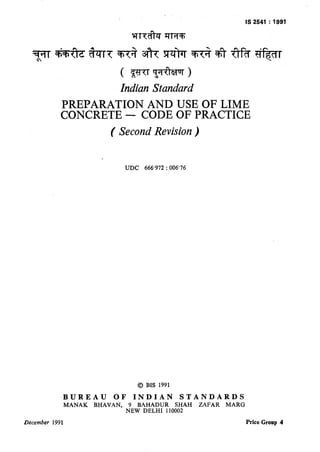
- 8. IS 2541: 1991 The dimensions of the specimens to the nearest 0’2 mm and their mass shall be noted before testing. B-11.2 Placing the Specimen in the Testing Machine The bearing surfaces of the testing machine shall be wiped clean and any loose sand or other material removed from the surfaces of the specimen which are to be in contact with the compression platens. In the case of cubes, the specimen shall be placed in the machine in such a manner that the load shall be applied to opposite vertical sides of the cubes as cast, that is, not to the top and bottom. The axis of the specimen shall be carefully aligned with the centre of thrust of the spherically seated platen. No packing shall be used between the faces of the test specimen and the steel platen of the testing machine. As the spherically seated block is brought to bear on the sp:cimen, the movable portion shall be rotated gently by hand so that uniform seating may be obtained. The load shall be applied without shock and increased continuously at a rate of approxi- mately 10’5 N/mma/min until the resistance of the specimen to the increasing load breaks down and no greater load can be sustained. The maximum load applied to the specimen shall then be recorded and the appearance of the concrete and any unusual features in the type of failure shall be noted. B-12 CALCULATION The measured compressive strength of the specimen shall be calculated by dividing thg maximum load applied to the specimen, durine the test by the cross-sectional area, calculated from the mean dimensions of the section and shall be expressed to the nearest 0.1 N/mm2. Average to three values shall be taken as the repres&tative of the batch provided individual variation is not more than percent of the average. shall be made. Otherwise repeat the f 15 tests ANNEX C ( Clause 5.6.2 ) METHOD OF TEST FOR DETERMINATION OF TRANSVERSE STRENGTH C-l PREPARATION OF SPECIMENS Preparation of materials, proportions, weighing, mixing of concrete, preparation and curing of specimen shall be done in the same way as in the case of compression test specimens given in B-l to B-7. C-2 SIZE OF SPECIMEN The size of specimen shall be 150 mm X 150 mm X 700 mm. C-3 APPARATUS The testing machine may be of any reliable type of sufficient capacity for the tests and capable of applying the load at the rate specified in C-4.2. The permissible errors shall be not greater than -+ 2 percent of the applied load. The bed of the testing machine shall be provided with two steel rollers, 38 mm in diameter, on which the specimen is to be supported, and these rollers shall be so mounted that the distance from centre to centre is 600 mm for 150 mm specimen. The load shall be applied through two similar rollers mounted at the third point of the supporting span, that is spaced at the 200 mm -entre to centre. The load shall be divided equally between the two loading rollers, and all rollers shall be mounted in such a manner that the load is applied axially and without subjecting the specimen to any torsional stresses or restraints. One suitable arrangement which complies with these requirements is indicated in Fig. 1. 6 C-4 PROCEDURE C-4.1 Test specimens stored in water at a temperature of 27” f 2°C before testing, shall be tested immediately on removal from the water whilst they are still in a wet condition. Specimens when received dry shall be kept in water for 22 h before they are taken for testing. The dimensions of each specimen shall be noted before testing. No preparation of the surfaces is required. C-4.2 Placing the Specimen in the Testiag Machine The bearing surfaces of supporting and loading rollers shall be wiped clean, and any loose sand or other material removed from the surfaces of the specimen where they are to make contact with the rollers. The specimen shall then be placed in the machine in such a manner that the load shall be applied to the uppermost surface as cast in the mould, along two lines spaced 200 mm apart. The axis of the specimen shall be carefully aligned with the axis of I:;B device. No packing shall be used loading _wee;l a.he bearing surfaces of the specimen rqd the rc’lers. The load shall be applied without shock, increasing continuously at a rate such that tbm extreme fibre stress increases at approximate’ 0’7 N/mm’/min, that is at 2 rate of loading o1 4 000 N/min. The load shall be increased until the specimen fails, and the maximum load applied to the sp-cimen during the test shall be recorded. The appearance of the fractured
- 9. IS 2541 : 1991 ATING BARS REMOVE0 LOADING IS COMMENC SECTION XX SECTION YV FIG. 1 ARRANGEMENTFORDETERMINATIONOF TRANSVERSESTRENGTH faces of concrete and any unusual features in the type of failure shall be noted. C-5 CAI&ULATION The flexural strength of the specimen shall be expressed as the modulus of rupture fb which, if ‘u’ equals the distance between the line of fracture and the nearer support, measured on the centre line of the tensile side of the specimen, in mm, shall be calculated to the nearest 0’05 N/mma as follows: PXl fb= bxd2 when ‘u’ is greater than 200 mm for 150 mm specimen or 3P X a fb= bxd2 When ‘u’ is less than the 200 mm but greater than 170 mm for 150 mm specimen where b = measured width, in mm, of the specimen; d = measured depth, in mm, of the specimen at the point of failure; I = length, in mm, of the span on which the specimen was supported; and P = maximum load in N applied to the specimen. If ‘a’ is less than 170 mm for a 150 mm specimen, the results of the test shall be discarded.
- 10. Standard Mark The use of the Standard Mark is governed by the provisions of the Bureau of Indian Standards Act, 1986 and the Rules and Regulations made thereunder. The Standard Mark on products covered by an Indian Standard conveys the assurance that they have been produced to comply with the requirements of that standard under a well defined system of inspection, testing and quality control which is devised and supervised by BIS and operated by the pro- ducer. Standard marked products are also continuously checked by BIS for conformity to that standard as a further safeguard. Details of conditions under which a licence for the use of the Standard Mark may be granted to manufacturers or producers may be obtained from the Bureau of Irdian Standards. i
- 11. Bureau of Indian Standards BIS is a statutory institution established under the Bureau of Indian Standavds Act, I986 to promoto harmonious development of the activities of standardization, morklng and quality certification of goods and attending to connected matters in the country. Copyright BIS has the copyright of all its publications. No part of these publications may be reproduced in any form without the prior permission in writing of BIS. This does not preclude the free use, in the course of implementing the standard, of necessary details, such as symbols and sizes, type or grade designations. Enquiries relating to copyright be addressed to the Director ( Publication ), BIS. Revision of Indian Standards Indian Standards are reviewed periodically and revised, when necessary and amendments, if any, are issued from time to time. Users of Indian Standards should ascertain that they are in possession of the latest amendments or edition. Comments on this Indian Standard may be sent to BIS giving the following reference : Dot : No. CED 4 ( 4877 ) Amendments Issued Since Publication 7. Amend No. Date of Issue Text Affected BUREAU OF INDIAN STANDARDS Headquarters : Manak Bhavan, 9 Bahadur Shah Zafar Marg, New Delhi 110002 Telephones : 331 01 31, 331 13 75 Telegrams : Manaksanstha ( Common to all Offices ) Regional 05ces : Telephones Central : Manak Bhavan, 9 Babadur Shah Zafar Marg, 331 01 31 NEW Delhi-l 10002 331 13 75 Eastern : l/14 C.I.T. Scheme VfI M, V.I.P. Road, Maniktola CALCUTTA 700054 37 86 62 Northern : SC0 445-446, Sector 35-C, CHANDIGARH 160’036 53 38 43 ’ Southern : C.I.T. Campus, IV Cross Road, MADRAS 600113 412916, Western : Manakalaya, E9 MlDC, Marol, Andheri ( East > BOMBAY 400093 6 32 92 95 Branches : AHMADABAD, BANGALORE, BHOPAL, BHUBANESHWAR, COIMBATORE, FARIDABAD, GHAZIABAD, GUWAHATI, HYDERABAD, JAIPUR, KANPUR, PATNA, THIRUVANANTHAPURAM. Printed at Swatantra l3harat Press, Delhi, India