Más contenido relacionado
La actualidad más candente (19)
Similar a 40220140504005 (20)
Más de IAEME Publication (20)
40220140504005
- 1. International Journal of Electrical Engineering and Technology (IJEET), ISSN 0976 – 6545(Print),
ISSN 0976 – 6553(Online) Volume 5, Issue 4, April (2014), pp. 39-48 © IAEME
39
MOVEMENT OF METALLIC PARTICLE CONTAMINANTS OF VARIOUS
DIMENSIONS IN 1-Ø DIELECTRIC COATED GAS INSULATED BUSDUCT
P. Nagarjuna Reddy
Department of Electrical and Electronics Engineering, Kakatiya Institute of Technology & Science
Warangal, AP, INDIA
J. Amarnath
Department of Electrical and Electronics Engineering, JNTUH College of Engineering
Hyderabad, AP, INDIA
ABSTRACT
Metallic particles in Gas Insulated Substation (GIS) have their origin mainly from the
manufacturing process or they may originate from moving parts of the system, such as breakers and
disconnectors. Depending on the shape of the particles, as well as the geometry and voltage levels of
the system, the particles get more or less influenced by the electric field which, in turn, makes them
hazardous to the electrical system, in terms of partial discharges and breakdown. Coating with thin
layer of epoxy type dielectric material on inner surface of outer enclosure of Gas Insulated Busduct
can increase the breakdown voltage of Gas Insulated System
In the present work, the Metallic contaminations of Cu and Al of various dimensions have
been considered. The simulation has been carried out for various power frequency voltages. The
electric field effect on the particle movement requires the calculation of the electric field which is
calculated by using analytical method and Charge simulation method. Typically a GIB of inner and
outer diameter 55/152mm has been considered. Wire like particles of radii varying from 0.01 to
0.04mm and length from 8mm to 15mm have been used for simulation. Co-efficient of restitution
and pressure have been held constant at 0.9 and 0.4 Mpa respectively.
Keywords: Particle Contamination, CSM, Analytical Method.
I. INTRODUCTION
Gas Insulated Substation (GIS) is a compact, multi-component assembly enclosed in a
ground metallic housing which the primary insulating medium is compressed sulphur hexafluoride
INTERNATIONAL JOURNAL OF ELECTRICAL ENGINEERING &
TECHNOLOGY (IJEET)
ISSN 0976 – 6545(Print)
ISSN 0976 – 6553(Online)
Volume 5, Issue 4, April (2014), pp. 39-48
© IAEME: www.iaeme.com/ijeet.asp
Journal Impact Factor (2014): 6.8310 (Calculated by GISI)
www.jifactor.com
IJEET
© I A E M E
- 2. International Journal of Electrical Engineering and Technology (IJEET), ISSN 0976 – 6545(Print),
ISSN 0976 – 6553(Online) Volume 5, Issue 4, April (2014), pp. 39-48 © IAEME
40
(SF6) gas. It generally consists of the components like Bus bars, Circuit Breakers, Disconnecting
switches, Earthing switches, Current transformers, Voltage transformers etc. Gas insulated
Substations have found a broad range applications in power systems over the last three decades
because of their high reliability, Easy maintenance, small ground space requirements etc. Although
GIS has been in operation in several years, some of the problems are needful attention. These
problems include VFTO during switching operations or earth faults and transient enclosure voltages
and particle contamination. A study of CIGRE group suggests that 20% of failure in GIS is due to
the existence of various metallic contaminations in the form of loose particles. Under the influence
of high voltage, they can acquire sufficient charge and randomly move in the gap due to the variable
electric field.
A) The necessity of this study
Extremely high dielectric properties of SF6 have long been recognized. Compressed SF6 has
been used as an insulating medium as well as arc quenching medium in electrical apparatus in a wide
range of voltages. Gas Insulated Substations (GIS) can be used for longer times without any
periodical inspections. Conducting contamination (i.e. aluminum, copper and silver particles) could,
however, seriously reduce the dielectric strength of gas-insulated system
B) The origin of these particles
Metallic particles in GIS have their origin mainly from the manufacturing process or they
may originate from moving parts of the system, such as breakers and disconnectors. Metallic
particles can be either free to move in the GIS or they may be stuck either to an energized electrode
or to an insulator surface (spacer, bushing etc. A metallic particle stuck on an insulator surface in a
GIS will also cause a significant reduction of the breakdown voltage
Depending on the shape of the particles, as well as the geometry and voltage levels of the
system, the particles get more or less influenced by the electric field which, in turn, makes them
hazardous to the electrical system, in terms of partial discharges and breakdown.
Conductors in a GIS/GITL system may be coated with a dielectric material to restore some
of the dielectric strength of the compressed gas, which is lost due to surface roughness and
contamination by conducting particles. The improvement in the dielectric strength of the system due
to coating can be attributed to several effects. Coating reduces the degree of surface roughness on
conductors. Also, the high resistance of the coating impedes the development of predischarges in
the gas, thus increasing the breakdown voltage (Morcos et al., 2000). The electric field necessary
to lift a particle resting on the inside surface of a GIB enclosure is much increased due to the
coating. With coated conductors the particle will acquire a drastically reduced charge, thus the risk
of breakdown initiated by a discharge is reduced significantly. Coating thickness has been varied
from a few microns to several millimeters and the influence of coated electrodes on the insulation
performance has been studied under ac voltages.
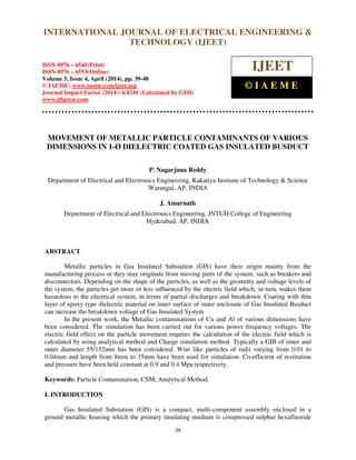
Fig. 1: Schematic diagram of a typical gas Insulated busduct
- 3. International Journal of Electrical Engineering and Technology (IJEET), ISSN 0976 – 6545(Print),
ISSN 0976 – 6553(Online) Volume 5, Issue 4, April (2014), pp. 39-48 © IAEME
41
In the present simulation work for the motion of metallic particles (Al, Cu and Ag wires)
busduct of 55mm / 152mm inner and outer diameter is considered. Also, the particle is on the surface
of the enclosure and the enclosure is earthed. The schematic diagram of a typical compressed Gas
insulated busduct is shown in Fig. (1).
II. METALLIC PARTICLES IN DIELECTRIC COATED GAS INSULATED BUSDUCT
Free conducting particles resting on dielectric coated inner surface of GIB enclosure gets
charged because of two different mechanisms
• Conduction through the dielectric coating
• Partial discharges initiated at particle surface.
The equivalent circuit of the model is shown in fig. 2.
Fig.2: Equivalent circuit model of charging particle in dielectric coated 1-Ф Gas Insulated Busduct
The charging current through metallic particle can be written as:
… (1)
The charge acquired by particle is obtained by integrating equation
… (2)
The lift off field of the particle is given by the equation:
… (3)
III. SIMULATION OF THE WIRE PARTICLE MOTION
The forces acting on the metallic particle contaminants are added and the movement of the
particle in the gas insulated busduct is simulated using the following equations.
- 4. International Journal of Electrical Engineering and Technology (IJEET), ISSN 0976 – 6545(Print),
ISSN 0976 – 6553(Online) Volume 5, Issue 4, April (2014), pp. 39-48 © IAEME
42
Theory of Particle motion
A conducting particle in motion in an external electrical field will be subjected to a collective
influence of several forces. The forces may be divided into:
- Electrostatic force (Fe)
- Gravitational force (mg)
- Drag force (Fd)
Electrostatic Force
The charge acquired by a vertical wire particle in contact with naked enclosure can be
expressed as:
1-
r
2l
ln
)(tEl
Qnet 0
2
0
∈π
= ... (4)
Where l is the particle length,
r is the particle radius,
E(t0) is the ambient electrical field at t = t0.
Analytical Method:
Disregarding the effect of charges on the particle, the electric field in a coaxial electrode system at
position of the particle can be written as:
[ ]
ω
=
i
0
0
r
r
lny(t)-r
tSinV
)t(E ... (5)
Where V is the voltage on the inner electrode
ro is the enclosure radius,
ri is the inner conductor radius
y(t) is the position of the particle which is the vertical distance from the surface of the
enclosure towards the inner electrode.
Charge Simulation Method:
Fig. 3: Basic Concept of Charge Simulation Method without image charges
- 5. International Journal of Electrical Engineering and Technology (IJEET), ISSN 0976 – 6545(Print),
ISSN 0976 – 6553(Online) Volume 5, Issue 4, April (2014), pp. 39-48 © IAEME
43
The Electrostatic field at point ‘p(x,y)’ is calculated by using the following equations:
−+−
−
= ∑=
3 22
1 )()(2
)(
ii
i
n
i
i
x
yyxx
xx
tE
πε
λ … (6)
−+−
−
= ∑=
3 22
1 )()(2
)(
ii
i
n
i
i
y
yyxx
yy
tE
πε
λ
… (7)
Where Ex(t), Ey(t) are Electrostatic field components at time instant ‘t’ along X(Horizontal) and
Y(Vertical)-axes respectively, x,y are coordinates of point ‘p’ where Electric field is to be calculated,
xi,yi are coordinates of ith
fictitious charge, n is the number of fictitious charges per phase, λi is line
charge density of ith
fictitious charge.
Fictitious charges with assignment factor are considered inside of each conductor of GIB for
calculating electric field in Charge Simulation Method.
The electrostatic force relating charge and electric field E(t) is given by :
E(t)QKF nete = ... (8)
Where K is a correction factor smaller than unity.
Gravitational Force:
The gravitational force is given by
glrmg 2
ρπ= ... (9)
Where r is the radius of the particle
L is the length of the particle
g is the acceleration due to gravity
ρ is the density of the particle
Drag force:
Drag is a result of energy dissipation in the shock wave near the particle and skin friction
along the surface of the particle. In spherical particles shock wave energy dissipation and in wire
particles skin friction is more significant. The direction of the drag force is always opposed to the
direction of motion of particle.
By considering all the forces the equation of motion can be written as
de2
2
F-mg-F
dt
yd
m = ... (10)
Where Fd is drag force.
The above equation is solved by Runge-Kutta method to obtain radial movement with time,
for various values of parameters.
- 6. International Journal of Electrical Engineering and Technology (IJEET), ISSN 0976 – 6545(Print),
ISSN 0976 – 6553(Online) Volume 5, Issue 4, April (2014), pp. 39-48 © IAEME
44
IV. RESULTS AND DISCUSSIONS
The radial movement of the particle contaminants is obtained by solving the motion equation
of metallic particle using RK 4th
Order method. The Electric fields are calculated by using Charge
Simulation Method as per the equations (6) and (7) and with Analytical Method using equation (5).
Table I: Maximum Radial Movements of Al particle of r=0.25mm
Sl.No. l(mm)
Applied Voltage
75KV 100KV 132KV 145KV 175KV 220KV
Analytical
method
CSM
Analytical
method
CSM
Analytical
method
CSM
Analytical
method
CSM
Analytical
method
CSM
Analytical
method
CSM
1. 8 3.0493 3.0472 4.6600 4.6552 7.4875 7.4816 8.5927 8.5863 11.0476 11.0403 14.4476 14.4393
2. 10 3.0653 3.0634 4.7522 4.7478 7.6446 7.6390 8.7797 8.7737 11.3019 11.2949 14.8104 14.8025
3. 12 3.0771 3.0751 4.8210 4.7939 7.7622 7.7565 8.9199 8.8828 11.4946 11.4522 15.0842 15.0353
4. 15 3.0902 3.0881 4.8975 4.8929 7.8937 7.8879 9.0768 9.0705 11.7111 11.7038 15.3936 15.3852
Table II: Maximum Radial Movements of Cu particle of r=0.25mm
Sl.No. l(mm)
Applied Voltage
75KV 100KV 132KV 145KV 175KV 220KV
Analytical
method
CSM
Analytical
method
CSM
Analytical
method
CSM
Analytical
method
CSM
Analytical
method
CSM
Analytical
method
CSM
1. 8 1.2719 1.2708 2.0256 2.0240 3.0213 3.0193 3.4297 3.4275 4.8987 4.8939 7.4507 7.4447
2. 10 1.2732 1.2722 2.0282 2.0268 3.0261 3.0241 3.4355 3.4333 4.9292 4.9243 7.5001 6.3565
3. 12 1.2742 1.2731 2.0302 2.0213 3.0297 3.0277 3.4399 3.4267 4.9517 4.9225 7.5364 7.5000
4. 15 1.2752 1.2741 2.0323 2.0308 3.0336 3.0316 3.4447 3.4425 4.9764 4.9715 7.5763 7.5702
Table III: Maximum Radial Movements of Al particle of l=12mm
Sl.No.
Radius
of
particle
(mm)
Applied Voltage
75KV 100KV 132KV 145KV 175KV 220KV
Analytical
method
CSM
Analytical
method
CSM
Analytical
method
CSM
Analytical
method
CSM
Analytical
method
CSM
Analytical
method
CSM
1. 0.01 3.0771 3.0751 4.8210 4.7939 7.7622 7.7565 8.9199 8.8828 11.4946 11.4522 15.0842 15.0353
2. 0.02 1.9043 1.9029 2.8926 2.8907 4.4970 4.4924 5.4291 5.4241 7.5580 7.5520 10.6726 10.6654
3. 0.03 1.3798 1.3787 2.1764 2.1748 3.2253 3.2232 3.6559 3.6536 5.4078 5.4027 8.0925 8.08620
4. 0.04 1.0734 1.0724 1.7501 1.7487 2.6507 2.6489 3.0231 3.0211 4.0480 4.0435 6.4188 6.4132
Table IV: Maximum Radial Movements of Cu particle of l=12mm
Sl.No.
Radius of
particle(mm)
Applied Voltage
75KV 100KV 132KV 145KV 175KV 220KV
Analytical
method
CSM
Analytical
method
CSM
Analytical
method
CSM
Analytical
method
CSM
Analytical
method
CSM
Analytical
method
CSM
1. 0.01 1.2742 1.2731 2.0302 2.0213 3.0297 3.0277 3.4399 3.4267 4.9517 4.9225 7.5364 7.5000
2. 0.02 0.6534 0.6527 1.1523 1.1513 1.8335 1.8322 2.1180 2.1165 2.7844 2.7825 3.9158 3.9113
3. 0.03 0.4029 0.8215 0.7823 0.7815 1.3160 1.3149 1.5420 1.5408 2.0750 2.0734 2.8942 2.8923
4. 0.04 0.2674 0.2670 0.5735 0.5728 1.0171 1.0161 1.2070 1.2060 1.6585 1.6572 2.3575 2.3559
- 7. International Journal of Electrical Engineering and Technology (IJEET), ISSN 0976 – 6545(Print),
ISSN 0976 – 6553(Online) Volume 5, Issue 4, April (2014), pp. 39-48 © IAEME
45
Fig 4: Al particle radial movement for 75kV with analytically calculated field for r=0.01mm
Fig.5: Cu particle radial movement for 100kV with analytically calculated field for r=0.25mm
Fig.6: Al particle radial movement for 145kV with CSM calculated field for r=0.01mm
Fig.7: Cu particle radial movement for 132kV with CSM calculated field for r=0.01mm
3.018
3.02
3.022
3.024
3.026
3.028
3.03
3.032
3.034
6 11 16
Max.Movement(mm)
Length of the particle(mm)
8.5
8.6
8.7
8.8
8.9
9
9.1
6 8 10 12 14 16
Max.Movement(mm)
Length of the particle(mm)
2.024
2.026
2.028
2.03
2.032
2.034
6 11 16
Max.
movement(mm)
Length of the particle(mm)
3.04
3.05
3.06
3.07
3.08
3.09
3.1
6 11 16
Max.movement(mm)
Length of particle(mm)
- 8. International Journal of Electrical Engineering and Technology (IJEET), ISSN 0976 – 6545(Print),
ISSN 0976 – 6553(Online) Volume 5, Issue 4, April (2014), pp. 39-48 © IAEME
46
Fig.8: Al particle radial movement for 75kV with analytically calculated field for l=12mm
Fig.9: Cu particle radial movement for 100kV with analytically calculated field for l=12mm
Fig.10: Al particle radial movement for 145kV with CSM calculated field for l=12mm
Fig.11: Cu particle radial movement for 132kV with CSM calculated field for r=0.25mm
0
0.5
1
1.5
2
2.5
3
3.5
0 0.02 0.04
Max.
movmement(mm)
Radius of the particle(mm)
0
2
4
6
8
10
0 0.02 0.04
Max.movement(mm)
Radius of the particle(mm)
0
0.5
1
1.5
2
2.5
0 0.02 0.04
Max.movement(mm)
Radius of the particel(mm)
0
0.5
1
1.5
2
2.5
3
3.5
0 0.02 0.04
Max.movement(mm)
Radius of the particle(mm)
- 9. International Journal of Electrical Engineering and Technology (IJEET), ISSN 0976 – 6545(Print),
ISSN 0976 – 6553(Online) Volume 5, Issue 4, April (2014), pp. 39-48 © IAEME
47
Computer simulations of motion for the metallic wire particles were carried out using
Advanced C Language Program in GIB of inner and outer diameter of 55/152mm for 75KV, 100KV,
132KV, 145KV,175 KV and 220 KV applied voltages. Aluminum and copper wire like particles
were considered to be present on the surface of enclosure. Monte-Carlo simulation is carried out to
determine the axial movement of the aluminum and copper particles for the random angle of 20
for
voltages ranging from 75kV to 400kV. The other parameters assumed for the simulation of Al and
Cu particles in dielectric coated single phase GIB are dielectric coating thickness 200micrometers,
pressure 0.4MPa and Restitution Coefficient 0.9.
Table I and Table II show the maximum movement patterns of aluminium and copper
particles of different lengths with radius 0.01mm at different power frequency voltages. The
movement of the Aluminium particle for fixed radius of 0.01mm at 75KV was observed to be
3.0493mm for a length of 8mm while it was 3.0902mm for a length of 15mm.The movements of the
same particles when Charge simulation method is employed for field calculations were found to be
3.0472mm and 3.0881mm respectively.
Table III and Table IV show the maximum movement patterns of various aluminium and
copper particles of different radii with length 12mm at different power frequency voltages. The
movement of the Aluminium particle for fixed length of 12mm at 75KV was observed to be
3.0771mm for a radius of 0.01mm while it was 1.0734 mm for a radius of 0.04mm.The movements
of the same particles when Charge simulation method is employed for field calculations were found
to be 3.0751mm and 1.0724mm respectively.
The Maximum movement for aluminium and copper particles with variation of lengths of the
particle for various voltages is shown in the Figs. 4 & 5 for field calculated using analytical method.
Fig 6 & 7 show the movement pattern of the aluminium and copper particles for different lengths
when the field is calculated using charge simulation method. The Maximum movement for
aluminium and copper particles with variation of radius of the particle for various voltages is shown
in the Figs. 8 & 9 for fields calculated using analytical method. Fig 10 & 11 show the movement
pattern of the aluminium and copper particles for different radii when the field is calculated using
charge simulation method.
V. CONCLUSION
The movement pattern of metallic particles with various dimensions in a 1-Ø dielectric
coated gas insulated busduct has been simulated by formulating a mathematical model. The electric
field is calculated using analytical method and charge simulation method. The maximum movement
of the both the aluminium and the copper particles was found to be less when the field is calculated
using charge simulation method when compared to that of the field calculated using analytical
method.
From the observations, of the investigations carried out on various power frequency voltages,
it is clear that as the radius increases, maximum movement for any type of particle decreases while
the maximum movement increases with the length of the particle.
VI. ACKNOWLEDGEMENTS
The authors are thankful to the managements Kakatiya Institute of Technology & Science,
Warangal, and JNTUH University, Hyderabad, for providing facilities and to publish this work.
- 10. International Journal of Electrical Engineering and Technology (IJEET), ISSN 0976 – 6545(Print),
ISSN 0976 – 6553(Online) Volume 5, Issue 4, April (2014), pp. 39-48 © IAEME
48
REFERENCES
1. H. Anis and K.D. Srivastava; “Movement of charged conducting particles under Impulse
Voltages in Compressed Gases”; IEEE Int. Conf. On industrial Applications ; 1980.
2. J. Amarnath, B.P. Singh, S. Kamakshaiah and C. Radhakrishna : “Determination of Particle
Trajectory in Gas Insulated Busduct by Monte-carlo technique” : CEIDP-99 (IEEE) during
Oct. 17-21, 1999, Austin, Texas, U.S.A.
3. J. Amarnath, B.P. Singh, S. Kamakshaiah and C. Radhakrishna : “Monte-Carlo Simulation of
Particle movement in a coated gas insulated substation for power frequency and switching
transients”: International High Voltage Workshop (IEEE) during April 10-12, 2000,
California, USA.
4. J. Amarnath, B.P. Singh, S. Kamakshaiah, C. Radhakrishna and K. Raghunath; “Movement of
metallic particles in gas insulated substations under the influence of various types of voltages”
: National Power System Conference (NPSC-2000) IISc, Bangalore 20th - 22nd Dec., 2000
accepted for publication.
5. M.M. Morcos, K.D. Srivastava and H. Anis: “Dynamies of Metallic Contaminants in
Compressed Gas Insulated Power Apparatus”; Fourth Int. Symposium on High Voltage
Engineering: Athens, 1983.
6. H. Anis and K.D. Srivastava : “Breakdown Characteristics of Dielectric coated electrodes in
Sulphur Hexafluoride Gas with Particle Contamination” ; Sixth International Symposium on
High Voltage Engineering , No. 32. 06, New Orleans, LA, USA, 1989.
7. H.Anis and K.D. Srivastava: “Free Conducting particles in Compressed Gas Insulation”:
IEEE Trans on Electrical Insulation, Vol EI-16, pp. 327-338, August, 1981.
8. H. Parekh, K.D. Srivastava and R.G. Van Heeswijk; “Lifting Field of Free Conducting
Particles in Compressed SF6 with Dielectric Coated Electrodes”; IEEE Transactions on Power
Apparatus and Systems, Vol. PAS-98, No. 3, May/June 1979.
9. Ahmed Thabet, “Experimental Investigation on Thermal Electric and Dielectric
Characterization for Polypropylene Nanocomposites using Cost-Fewer Nanoparticles”,
International Journal of Electrical Engineering & Technology (IJEET), Volume 4, Issue 2,
2013, pp. 1 - 12, ISSN Print : 0976-6545, ISSN Online: 0976-6553.
10. Ahmed Thabet, “Influence of Cost-Less Nanoparticles on Electric and Dielectric
Characteristics of Polyethylene Industrial Materials”, International Journal of Electrical
Engineering & Technology (IJEET), Volume 4, Issue 1, 2013, pp. 58 - 67, ISSN Print:
0976-6545, ISSN Online: 0976-6553.
11. Sandeep Dhariwal, Vijay K. Lamba and Ritu Vijay, “Analyzing the Transport Properties of
Metallic Swcnt Interconnects between Gold Electrodes”, International Journal of Electronics
and Communication Engineering & Technology (IJECET), Volume 3, Issue 2, 2012,
pp. 451 - 460, ISSN Print: 0976- 6464, ISSN Online: 0976 –6472.