Bj34385389
•
1 recomendación•295 vistas

International Journal of Engineering Research and Applications (IJERA) is an open access online peer reviewed international journal that publishes research and review articles in the fields of Computer Science, Neural Networks, Electrical Engineering, Software Engineering, Information Technology, Mechanical Engineering, Chemical Engineering, Plastic Engineering, Food Technology, Textile Engineering, Nano Technology & science, Power Electronics, Electronics & Communication Engineering, Computational mathematics, Image processing, Civil Engineering, Structural Engineering, Environmental Engineering, VLSI Testing & Low Power VLSI Design etc.

Recomendados
Recomendados
Más contenido relacionado
La actualidad más candente
La actualidad más candente (17)
Destacado
Destacado (20)
Similar a Bj34385389
Similar a Bj34385389 (20)
Último
Último (20)
Bj34385389
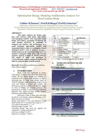
- 1. VaibhavR.Pannase, Prof.H.R.Bhagat, Prof.R.S.Sakarkar/ International Journal of Engineering Research and Applications (IJERA) ISSN: 2248-9622 www.ijera.com Vol. 3, Issue 4, Jul-Aug 2013, pp. 385-389 385 | P a g e Optimization Design, Modeling AndDynamic Analysis For Wind Turbine Blade Vaibhav R.Pannase1 , Prof.H.R.Bhagat2 ,Prof.R.S.Sakarkar3 1 (Department of Mechanical Engineering, BabasahebNaik College of Engineering.,Pusad 2 (H.O.D.,Department of Mechanical Enginering, Jagadambha College of Engg.& Technology.,Yavatmal 3 (Department of Mechanical Enginering, Jagadambha College of Engg.& Technology.,Yavatmal ABSTRACT This paper explores the design space that exists between multi blade, high-solidity water-pumping turbines with trapezoidal blade design and modern rectangular horizontal axis wind turbines (HAWTs). In particular, it compares the features and performance of a small 18-bladed, high-solidity HAWT with trapezoidal blade to that of a rectangular bladed 18-bladed HAWT. This is achieved through a Modal analysis on the exist trapezoidal blade and optimize rectangular blade along with dynamic response analysis of blade in ANSYS software. The model of blade was developed in CATIA.Dynamic analysis was performed for the blade by using the finite element method. Keywords–Blade Design,optimization; modeling; finite element analysis I. INTRODUCTION Blade is the key component to capture wind energy. It plays a vital role in the whole wind turbine. In this paper, design and analysis are conducted with layered shell elements to treat a horizontal axis 18- blade wind turbine based on ANSYS. The paper studied about the design of exist wind mill located at Pusad and compare the performance and life of blade with optimize design on basis of Modal and dynamic analysis. The optimization of blade is carried out by considering parameter like shapes of blade profile, stresses, deflection and buckling on blade. Referring to data of exist wind mill blade provide by wind turbine company, parameters of the blade were given as follows: Design wind speed V=7m/s, rotor diameter D=3m, blade number B=18. Tip speed ratio range of Low-speed wind turbines, λ = 1.6 Optimum angle of attack = 300 According Design data book the applied Lift coefficient=1.3,Drag coefficient=0.1. Lift Force on Blade=14.82 N Drag Force on Blade=1.1403 N Table: 1Technical Specification of Blade II. MODELING OF EXIST BLADE DESIGN (Rectangular Shape) Fig: 2.1 Model of Blade Fig: 2.2Models of Blade& Rotor Sr. No. Parameters Specification 1 No. of Blade 18 Nos. 2 Blade Materials Galvanized Iron 3 Size of Blade (Trapezoidal Shape) 920×440×195mm 4 Area of Blade 0.291 m2 5 Thickness of Blade 1mm 6 Angle ofAttackof Blade 300 7 Rotor Diameter 3 meter
- 2. VaibhavR.Pannase, Prof.H.R.Bhagat, Prof.R.S.Sakarkar/ International Journal of Engineering Research and Applications (IJERA) ISSN: 2248-9622 www.ijera.com Vol. 3, Issue 4, Jul-Aug 2013, pp. 385-389 386 | P a g e III. DYNAMIC FINITE ELEMENT ANALYSIS OF THE EXIST BLADE Dynamic finite element analysis of the blade mainly refers to the vibration modal analysis using the finiteElement theory. Modal analysis is used to identify natural frequencies, especially low- order frequencies and vibration modes of wind turbine blades. From the modal we can learn in which frequency range the blade will be more sensitive to vibrate. Blades should be designed to avoid the resonance region with the tower and other components in order to prevent some destruction of related components. In this paper, the finite model of the blade has been established in ANSYS by importing the blade surface model created previously combined with the actual layer structure of the existing blades. Modal analysis was carried out to check whether the mechanical properties of the blade meet certain safety requirements. a. Finite Element Modeling The finite element analysis of blade is carried out in ANSYS software. The design of blade imported from CATIA software which was analyzed in ANSYS. The shell unit shell 63 was chosen to simulatestructure of blade. Thematerial properties were approximately defined as isotropic, as the blade was made of galvanized iron materials. The material number and properties were defined by the Material Models menu. The corresponding real constants were distributed to every part of the blade and appropriate grid size was set. All the areas were meshed by MASHTOOL in the way of Free Mesh. The created FEM model of the blade consisted of 810elements, 776 nodes (Fig. 3.1) shows the lamination attribute of one selected element. Fig: 3.1FEM blade model b. Modal Analysis of Blade There are many ways for ANSYS modal analysis, of which the Block Lanczos method is most widely used because of its powerful features. Moreover, it is frequently applied with model of solid units or shell units that is why this paper chose Block Lanczos to perform the modal analysis. The vibration modes of the first five orders were extracted with the frequency range of 0~9999Hz. The connections of blades and rotor could beregarded as fixed, so it is only need to restrict all DOFs of the root, for modal analysis does not require applying loads. At last, after solving with the solver, the vibration modes of all the orders (Fig. 3.2) and the result of frequencies (Table 1) could be observed in the post-processor.
- 3. VaibhavR.Pannase, Prof.H.R.Bhagat, Prof.R.S.Sakarkar/ International Journal of Engineering Research and Applications (IJERA) ISSN: 2248-9622 www.ijera.com Vol. 3, Issue 4, Jul-Aug 2013, pp. 385-389 387 | P a g e Fig: 3.2 The first five vibration modes of the blade Table 1. Frequencies of the first five orders Mode orders 1 2 3 4 5 Frequencies 72.40 191.40 454.88 532.95 678.97 IV. OPTIMIZATION OF EXIST BLADE DESIGN The optimization of Exist blade design is carried out on basis of different parameters like shape profile of blade, Maximum Stresses and deflection on blade surface. These parameters are very important for consideration. The design of Wind Mill Rotor is design such that its pumped 1800 Liters of Water per day. a. Annual Energy consumption per Year The energy required to pumped 1800 Liters water from a well of depth about 25 m is about 120 Watts per Day approximately. Total annual energy consumption = Energy consumption per hour × Total annual hours Total annual energy consumption = 120×8760 =1051.200 kwh But this is the energy when wind will flow at rated wind speed throughout the year, which is never a case. Therefore in order to get realistic energy output, we have to multiply the above numbers by the capacity factor. For wind energy capacity factor is assumed to be 30 %.) [11] Annual Energy Production = 120× 8760 × 0.3 = 315.360 kwh Estimation of the annual energy output of a wind machine using capacity factor is an approximate method for finding annual output. For more accurate analysis, one should know long term wind distribution. b. Estimation of Required Windmill Power Rating The total energy annual requirement is 1100 kwh. Then what should be the size of wind turbine that is required to be installed to meet the energy requirement. Annual Energy Requirement =1100kwh Coefficient of Performance = 0.40 Wind Speed at Height of 15 meter = 7m/s Density of air = 1.22 kg/m3 Capacity Factor = 0.30 (30% of the time, wind machine is producing energy at rated power) No. of Hours in Year = 8760 Hours c. Calculation of Power Density of Wind (Power per unit Area) Ideal Power density of air = 1 2 × 𝜌 × 𝑉3 = 0.5×1.22× (7×7×7) = 171.5 w/m2 Actual power density that will be converted to useful energy = coefficient of performance× other losses By considering Other losses = 0.324 Actual power density = 171.5×0.324 = 55.55 w/m2 Annual energy density (useful) = power density× no of hours per Year = 55.55×8760 = 486.75 kwh/m2 By considering the capacity factor (30%) Real annual energy density = Annual energy density (useful) × capacity factor = 486.75×0.30 =146.02 kwh/m2 d. Calculation of Rotor (Blade) Size Area of the rotor = Total annual energy required / Real annual energy density = 1051.200 / 146.02 = 7.199 m2 e. Radius of Rotor (R) 𝐴 = 𝜋𝑅2 7.199 = 𝜋𝑅2 𝑅 = 1.514 𝑚 Diameter of Rotor =3 m f. Power Rating of Windmill = Actual power density × Area of Rotor = 55.55 × 7.199 =399.904 watts V. MODELING OF OPTIMIZE BLADE DESIGN In this section the modeling of optimizes blade design is carried out on basis of calculated data in CATIA modeling software. The blade is having size of 920×400mm with optimum incident angle of 300 . Fig: 4.1 Modal of Blade
- 4. VaibhavR.Pannase, Prof.H.R.Bhagat, Prof.R.S.Sakarkar/ International Journal of Engineering Research and Applications (IJERA) ISSN: 2248-9622 www.ijera.com Vol. 3, Issue 4, Jul-Aug 2013, pp. 385-389 388 | P a g e Fig:4.2 Modal of Blade with rotor assembly VI. DYNAMIC FINITE ELEMENT ANALYSIS OF THE OPTIMZE BLADE The modal which has been created in CATIA modeling software imported in ANSYS and treated that blade shape as SHELL 63 element and the dynamics analysis was carried out. Modal analysis was carried out to check whether the mechanical properties of the new blade design meet certain safety requirements. The created FEM model of the blade consisted of 710 elements, 715 nodes (Fig.5 (a)) shows the lamination attribute of one selected element. Fig: 4.3 Meshing of Optimize Blade design a. Finite Element Analysis The vibration modes of the first five orders were extracted with the frequency range of 0~9999Hz. The connections of blades and rotor could beregarded as fixed, so it is only need to restrict all DOFs of the root, for modal analysis does not require applying loads. At last, after solving with the solver, the vibration modes of all the orders (Fig. 6) and the result of frequencies (Table 2) could be observed in the post-processor. Fig: 4.4 First Five modes of Vibrations Table 2. Frequencies of the first five orders Mode orders 1 2 3 4 5 Frequencies 117.9 279.09 555.36 675.36 728.14 VII. RESULTS & DISCUSSION From Modal analysis carried out on exist and optimize blade it is found that the dynamic response for new rectangular blade is improved rather than exist design. The maximum resonance frequency of exist blade(Trapezoidal Shape) design is about 650Hz,whichhas to be improved up to 720Hz in new blade design (Rectangular Shape). VIII. CONCLUSION
- 5. VaibhavR.Pannase, Prof.H.R.Bhagat, Prof.R.S.Sakarkar/ International Journal of Engineering Research and Applications (IJERA) ISSN: 2248-9622 www.ijera.com Vol. 3, Issue 4, Jul-Aug 2013, pp. 385-389 389 | P a g e This paper applied to realize the aerodynamic contour optimization design of wind turbine blade. The way of combining CATIA and ANSYS was adopted to establish the blade model so as to describe actual shape and layer structure of the blade precisely. The dynamic performance of the exist blade (Trapezoidal Shape) and new blade (Rectangular Shape)was checked by modal analysis, providing a reference for structure design and other analyses. REFERANCES [1] NitinTenguriaet.al.“Design and Finite Element Analysis of Horizontal Axis Wind Turbine blade” International Journal of Applied Engineering Research, Dindigul Volume 1, No 3, 2010 ISSN 09764259. [2] Mr. Jesus Vega Fuentes,et.al. “Design of wind turbine blades of a power of 1000 watts for domestic use.” 978-1-61284- 1325-5/12, 2012 IEEE. [3] Mr.V. DíazCasás, et.al. “Automatic Design and Optimization of Wind Turbine Blades” International Conference on Computational Intelligence for Modeling Control and Automation, and International Conference on Intelligent Agents, Web Technologies and Internet Commerce 0-7695-2731- 0/06,IEEE. [4] Arvind Singh Rathore et al., “Design and Analysis of Horizontal Axis Wind Turbine Rotor”., International Journal of Engineering Science and Technology (IJEST) Vol. 3 No.11 November 2011 ISSN : 0975-5462. [5] Jialin Zhang, et.al. “Design and Research of High-Performance Low-Speed Wind Turbine Blades. “November 2011.IEEE. [6] Damien Castaignet, et.al., “Model Predictive Control of Trailing Edge Flaps on a Wind Turbine Blade”., 2011 American Control Conference on O'Farrell Street, San Francisco, CA, USA June 29 - July 01, 2011., 978-1-4577-0081-1/11 2011 AACC. [7] Jui-Sheng Chou , Chien-Kuo Chiu , I-Kui Huang, Kai-Ning Chi., “Failure analysis of wind turbine blade under critical wind loads Engineering Failure Analysis”., 27 (2013) 99–118 Available online 13 September 2012 Published by Elsevier Ltd. [8] Fangfang Song, Yihua Ni, ,Zhiqiang Tan “Optimization Design, Modeling and Dynamic Analysis for Composite Wind Turbine Blade." International Workshop of Automobile, Power and Energy Engineering ProcediaEngineering 2011 369 – 375 1877-7058 © 2011 Published by Elsevier Ltd. [9] RachidYounsi,et.al..,“Dynamic study of a wind turbine blade with horizontal axis”. Eur. J. Mech. A/Solids 20 (2001) 241–252 29 September 2000)2001 Éditions scientifiques et médicales Elsevier. [10] Karam Y. Maalawi, Hani M. Negm.,“Optimal frequency design of wind turbine Blades”. Journal of Wind Engineering and Industrial Aerodynamics 90 (2002) 961–986 9 April 2002. Elsevier Science.