Ce35461464
•
0 recomendaciones•234 vistas

International Journal of Engineering Research and Applications (IJERA) is an open access online peer reviewed international journal that publishes research and review articles in the fields of Computer Science, Neural Networks, Electrical Engineering, Software Engineering, Information Technology, Mechanical Engineering, Chemical Engineering, Plastic Engineering, Food Technology, Textile Engineering, Nano Technology & science, Power Electronics, Electronics & Communication Engineering, Computational mathematics, Image processing, Civil Engineering, Structural Engineering, Environmental Engineering, VLSI Testing & Low Power VLSI Design etc.

Recomendados
Recomendados
Más contenido relacionado
La actualidad más candente
La actualidad más candente (19)
Destacado
Similar a Ce35461464
Similar a Ce35461464 (20)
Último
Último (20)
Ce35461464
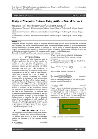
- 1. Syed Saleem Uddin et al. Int. Journal of Engineering Research and Application www.ijera.com Vol. 3, Issue 5, Sep-Oct 2013, pp.461-464 www.ijera.com 461 | P a g e Design of Microstrip Antenna Using Artificial Neural Network Shivendra Rai1 , Syed Saleem Uddin2 , Tanveer Singh Kler3 1 (Department of Electronics & Communication Lakshmi Narain College of Technology & Science, Bhopal, India) 2 (Department of Electronics & Communication Lakshmi Narain College of Technology & Science, Bhopal, India) 3 (Department of Electronics & Communication Lakshmi Narain College of Technology & Science, Bhopal, India) ABSTRACT: This paper presents the general design of microstrip antennas using artificial neural networks for rectangular patch geometry. The design consists of synthesis in the forward side and then analyzed as the reverse side of the problem. In this work, the neural network is employed as a tool in design of microstrip antennas. The neural network training algorithms are used in simulation of results for training the samples to minimize the error and to obtain the geometric dimensions with high accuracy for selective band of frequencies. Keyword: Artificial Neural Network, Microstrip antennas, Patch antennas. I. INTRODUCTION Microstrip antennas are being frequently used in Wireless application due to its light weight, low profile, low cost and ease of integration with microwave circuit. However standard rectangular microstrip antenna has the drawback of narrow bandwidth and low gain. The bandwidth of microstrip antenna may be increased using several techniques such as use of a thick or foam substrate , cutting slots or notches like U slot , E shaped , H shaped patch antenna, introducing the parasitic elements either in coplanar or stack configuration, and modifying the shape of the radiator patch by introducing the slots. In the present work an Artificial Neural Network (ANN) model is developed to analyze the bandwidth of the microstrip antenna. The Method of Moments (MOM) based IE3D software has been used to generate training and test data for the ANN. It is a computational EM simulator based on method of moment numerical method. It analyses 3D and multilayer structures of general shapes. The feed point must be located at that point on the patch, where the input impedance of patch matched with feed for the specified resonating frequency. The return loss is recorded and that feed point is selected as the optimum one where the RL is most negative i.e. less than or equal to -10Db II. ANTENNA DESIGN LAYOUT For designing a rectangular microstrip patch antenna, the length and the width are calculated as below: (1) Where c is the velocity of light, is the dielectric constant of substrate, f is the antenna working frequency ----------(1) Where c is the velocity of light, is the dielectric constant of substrate, f is the antenna working frequency, W is the patch non resonant width, and the effective dielectric constant is given as, eff -------(2) The extension length is calculated as, - ---------(3) using the mentioned equation we can find the value of actual length of the patch as, --------(4) Figure 1 shows the designed antenna geometry. The antenna is designed using air dielectric of height 10 mm. The length and width of the patch is 52 mm and 71 mm. On this patch a C slot is digged of dimensions 39 mm by 4 mm. The slot cutting is done to improve the bandwidth of the microstrip antenna. Fig 1. Geometry of proposed microstrip antenna RESEARCH ARTICLE OPEN ACCESS
- 2. Syed Saleem Uddin et al. Int. Journal of Engineering Research and Application www.ijera.com Vol. 3, Issue 5, Sep-Oct 2013, pp.461-464 www.ijera.com 462 | P a g e III. NETWORK ARCHITECTURE AND TRAINING: RADIAL BASIS FUNCTION NETWORK Fig 2. neural network approach In this paper, radial basis function (RBF) neural network is used to design and analyze C Shape microstrip patch antenna. Radial basis function network is a feed forward neural network with a single hidden layer that use radial basis activation functions for hidden neurons. RBF networks are applied for various microwave modeling purposes. The RBF neural network has both a supervised and unsupervised component to its learning. It consists of three layers of neurons – input, hidden and output. The hidden layer neurons represent a series of centers in the input data space. Each of these centers has an activation function, typically Gaussian. The activation depends on the distance between the presented input vector and the centre. The further the vector is from the centre, the lower is the activation and vice versa. The generation of the centers and their widths is done using an unsupervised k-means clustering algorithm. The centers and widths created by this algorithm then form the weights and biases of the hidden layer, which remain unchanged once the clustering has been done. A typical RBF network structure is given in figure 2 and model of ANN is shown Fig 3. ANN model . The parameters cij and λij are centers and standard deviations of radial basis activation functions. Commonly used radial basis activation functions are Gaussian and multiquadratic. Given the inputs x, the total input to the ith hidden neuron γi . Where N is the number of hidden neurons, The output value of the ith hidden neuron iszij = σ(γi), Where (γ) is a radial basis function. Finally, the outputs of the RBF network are computed from hidden neurons wki is the weight of the link between the ith neuron of the hidden layer and the kth neuron of the output layer.Training parameters w of the RBF network include wk0, wki , cij , λij, k = 1 ,2, . . . , m, i = 1,2, . . . .,N, j = 1,2, . . . n Fig 4. Training performance Fig 5. Radiation pattern TABLE 1: Outputs SLOT LENGTH (L1) SLOT WIDTH (W1) PROBE (X1,Y1) BW IE3D (GHz) BW RBF (GHz) BW WITH OUT SLOT (GHz) 39 4.2 8,14 0.370, 0. 519 0.368, 0.515 0.330, 0.452 39 4.2 9, 14 0.389, 0. 551 0.385, 0.553 0.330, 0.452 39 4.2 10, 14 0.253, 0.518 0.250, 0.514 0.330, 0.452 39 4.2 11, 14 0.392, 0. 507 0.396 0.509 0.330, 0.452 39 4.2 12, 14 0.355, 0. 471 0.355, 0.472 0.330, 0.452 39 4.2 13, 14 0.296, 0.343 0.299, 0.340 0.330, 0.452
- 3. Syed Saleem Uddin et al. Int. Journal of Engineering Research and Application www.ijera.com Vol. 3, Issue 5, Sep-Oct 2013, pp.461-464 www.ijera.com 463 | P a g e IV. RESULTS AND DISCUSSIONS Figure 7 shows the return loss graph of microstrip antenna for different positions of probe feed. The results are also depicted in Table 1. From the table it is evident that the result obtained from IE3D and ANN tool is very close by and hence giving accurate results after several trainings. The Length and width of the patch is kept constant and probe position is changed and the network is trained for the same adjustment. Further it is seen that the network analyzes the almost same bandwidth as obtained from the simulator. The ANN tool is just used to study the bandwidth of microstrip antenna which is in good agreement with the results obtained from Zeland IE3D software. Figure 6 shows the return loss graph of microstrip antenna which is about -38db. The proposed antenna gives a bandwidth of 17.78% covering the range of 1.90 to 2.27 GHz and 15.67% covering the range of 3.052 to 3.570 GHZ making it suitable broadband applications. Figure 5 & 7 shows the 2D radiation pattern and the 3D radiation pattern. The radiation pattern at 3.11 GHz frequency is shown in the figure. The component E theta at phi = 0 is shown giving a power gain of 1.56117dB.Figure 6 shows the 3D structure of proposed antenna. Figure 8 shows the Smith chart Vs Frequency plot which shows the input impedance and S11 parameter. The structure is simulated using IE3D simulation software. Fig 6. Return loss vs frequency plot Fig 7. Return loss vs. frequency plot Fig 8. 3D structure of the antenna Fig 9. Smith chart of proposed antenna V. FUTURE ENHANCEMENT The explosive growth in the demand for wireless communication and information transfer using handsets and personal communications (PCS) devices has created the need for major advancements of antenna designs as a fundamental part of any wireless system. One type of antennas that fulfills most of the wireles systems requirements is the microstrip antennas. These antennas are widely used on base stations as well as handheld devices. Microstrip antennas have a variety of configurations and are currently the most active field in antenna research and development. The microstrip antennas, due to their great advantages, have increasingly wide range of applications in wireless communication systems as handheld mobile devices, satellite communication systems, and biomedical applications. In most PCS, the handheld antenna is placed on a small plastic/shielding box that is in close proximity to biological tissue of user body hence its radiation may cause health hazardous effects. Added to the operational requirements, the users and service providers usually demand wireless units with
- 4. Syed Saleem Uddin et al. Int. Journal of Engineering Research and Application www.ijera.com Vol. 3, Issue 5, Sep-Oct 2013, pp.461-464 www.ijera.com 464 | P a g e antennas that are small and compact, cost effective for manufacturability, low profile, and easy to integrate with other wireless communication system components. The antenna designer must consider all these issues besides the electrical characteristics of the antenna performance which include antenna tuning (operating frequency), VSWR and return loss (input impedance), bandwidth, gain and directivity, radiation pattern, diversity, and size of the chassis and specific absorption rate (SAR) of the antenna. These design considerations have led antenna designers to consider a wide variety of structures to meet the often conflicting needs for different applications. New designs are investigated for several wireless communication applications. We hope the readers and researches of microstrip antenna systems will find in this special issue not only new designs about different microstrip antenna characteristics but also valuable information about numerical analysis and fabrications. VI. CONCLUSION In this work ANN is used as a tool to study the bandwidth of Microstrip Antenna. The results obtained from IE3D and those obtained from ANN are in good agreement and shows almost 99% accuracy. The training and test set has been designed with the data obtained from IE3D simulator. VII. ACKNOWLEDGMENT Every work started and carried out with systematic approach turns out to be successful. Any accomplished requires the effort of many people and this work is no different. The timely guidance of them has seen us through all these odds. We are very grateful to them for their inspiration, encouragement and guidance in all phases of the endeavor. It is my great pleasure to thank Mr. Mayank Mishra & Mr. Sayed Tazen Ali, assistant professors, department of electronics and communication, for his constant encouragement and valuable advice during the course of our project. We also wish to express our gratitude towards all other staff members for their kind help. Regardless of source we wish to express our gratitude to those who may contributed to this work, even though anonymously. REFERENCES [1] V.V. Thakre, P.K. Singhal “ Bandwidth analysis by introducing slots in Microstrip antennas design using ANN”. [2] K. Guney, N. Sarikaya “Comparison of adaptive-network-based fuzzy inference systems for bandwidth calculation and rectangular microstrip antennas”. [3] Narayana, J.L.” Design of Microstrip antennas using artificial neural networks” [4] W.Silabut, V.Kesornpatumanun, W.Wongtrairat “Improvement of antenna return loss using binary particl swarm optimization”. [5] A. Patnaik, R. K. Mishra, G. K. Patra, and S. K. Dash, “An Artificial Neural Network Model for Effective DielectricConstant of Microstrip Line”. [6] A. Patnaik and R. K. Mishra, “ANN Techniques in Microwave Engineering”.