

Recomendados
Recomendados
Más contenido relacionado
La actualidad más candente
La actualidad más candente (17)
Destacado
Destacado (20)
Similar a Nb2421482152
Similar a Nb2421482152 (20)
Nb2421482152
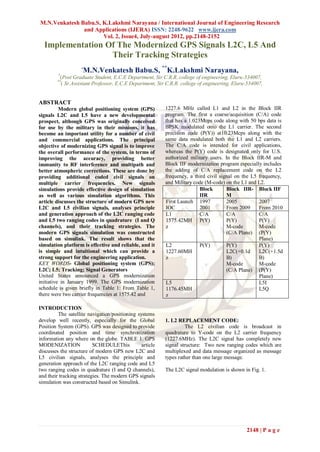
- 1. M.N.Venkatesh Babu.S, K.Lakshmi Narayana / International Journal of Engineering Research and Applications (IJERA) ISSN: 2248-9622 www.ijera.com Vol. 2, Issue4, July-august 2012, pp.2148-2152 Implementation Of The Modernized GPS Signals L2C, L5 And Their Tracking Strategies M.N.Venkatesh Babu.S, **K.Lakshmi Narayana, * * (Post Graduate Student, E.C.E Department, Sir C.R.R. college of engineering, Eluru-534007, ** ( Sr.Assistant Professor, E.C.E Department, Sir C.R.R. college of engineering, Eluru-534007, ABSTRACT Modern global positioning system (GPS) 1227.6 MHz called L1 and L2 in the Block IIR signals L2C and L5 have a new developmental program. The first a coarse/acquisition (C/A) code prospect, although GPS was originally conceived that has a 1.023Mcps code along with 50 bps data is for use by the military in their missions, it has BPSK modulated onto the L1 carrier. The second become an important utility for a number of civil precision code (P(Y)) at10.23Mcps along with the and commercial applications. The principal same data modulated both the L1 and L2 carriers. objective of modernizing GPS signal is to improve The C/A code is intended for civil applications, the overall performance of the system, in terms of whereas the P(Y) code is designated only for U.S. improving the accuracy, providing better authorized military users. In the Block IIR-M and immunity to RF interference and multipath and Block IIF modernization program especially includes better atmospheric corrections. These are done by the adding of C/A replacement code on the L2 providing additional coded civil signals on frequency, a third civil signal on the L5 frequency, multiple carrier frequencies. New signals and Military code (M-code) on the L1 and L2. simulations provide effective design of simulation Block Block IIR- Block IIF as well as various simulation algorithms. This IIR M article discusses the structure of modern GPS new First Launch 1997 2005 2007 L2C and L5 civilian signals, analyses principle IOC 2001 From 2009 From 2010 and generation approach of the L2C ranging code L1 C/A C/A C/A and L5 two ranging codes in quadrature (I and Q 1575.42MH P(Y) P(Y) P(Y) channels), and their tracking strategies. The z M-code M-code modern GPS signals simulation was constructed (C/A Plane) (P(Y) based on simulink. The result shows that the Plane) simulation platform is effective and reliable, and it L2 P(Y) P(Y) P(Y) is simple and intuitional which can provide a 1227.60MH L2C(+0.1d L2C(+1.5d strong support for the engineering application. z B) B) KEY WORDS- Global positioning system (GPS); M-code M-code L2C; L5; Tracking; Signal Generators (C/A Plane) (P(Y) United States announced a GPS modernization Plane) initiative in January 1999. The GPS modernization L5 L5I schedule is given briefly in Table 1: From Table 1, 1176.45MH L5Q there were two carrier frequencies at 1575.42 and z INTRODUCTION The satellite navigation/positioning systems develop well recently, especially for the Global 1. L2 REPLACEMENT CODE: Position System (GPS). GPS was designed to provide The L2 civilian code is broadcast in coordinated position and time synchronization quadrature to Y-code on the L2 carrier frequency information any where on the globe. TABLE 1. GPS (1227.6MHz). The L2C signal has completely new MODENIZATION SCHEDULEThis article signal structure: Two new ranging codes which are discusses the structure of modern GPS new L2C and multiplexed and data message organized as message L5 civilian signals, analyses the principle and types rather than one large message. generation approach of the L2C ranging code and L5 two ranging codes in quadrature (I and Q channels), The L2C signal modulation is shown in Fig. 1. and their tracking strategies. The modern GPS signals simulation was constructed based on Simulink. 2148 | P a g e
- 2. M.N.Venkatesh Babu.S, K.Lakshmi Narayana / International Journal of Engineering Research and Applications (IJERA) ISSN: 2248-9622 www.ijera.com Vol. 2, Issue4, July-august 2012, pp.2148-2152 This article does not deal with the position calculation, so data message is binary system random code here, which does not have any practicality meanings. 2. THE NEW CIVILIAN SIGNAL-L5: L5 is a new third civilian code that is broadcast in the ARNS band on a carrier frequency of 1176.45MHz. L5 is only available on Block IIF satellites. Independent operation from GPS L1/L2 means L5 is suited to Safety-of-Life applications. It has 24MHz signal bandwidth, and brands new signal structure. The L5 signal modulation is shown in Fig. 2. As see in Fig. 2, L5 has two components, an in-phase component (I5) and a quadrature component (Q5). The inphase code (I) has data and a ranging Figure 1. GPS L2C code signal modulation diagram code that are both modulated via BPSK onto the carrier. The data rate is 50 bps, but since it is coded The L2C signal consists of two codes: CM with a rate 1/2, K=7 convolutional code the symbol code (medium length code) and CL code (long length rate is 100sps. The I5 code is multiplied by an code). Neumann-Hoffman (NH) code to extend the code period to 10ms from 1ms. 1.a. CM (medium length code) The CM code is modulated with data at 25 bps, convolutionally encoded with parameters K=7 and rate 1/2, to produce 50sps data. The CM code is short cycled to 10230 chips and repeats every 20msecs. The chip rate is 0.5115Mcps. 1.b. CL (long length code) The CL code has no data modulation; the spreading is due to the spreading code. The CL code is short cycled to 767250 chips, so it repeats every 1.5secs and is synchronous with legacy. The chip rate is also 0.5115Mcps. Since there is no data on the CL code it can be carrier tracked by a phase locked loop (PLL), and a Costas or Squaring loop is not required. This is an important characteristic of the modern GPS Figure 2. GPS L5 signal modulation diagram. signals. The quadrature code (Q) has no data Both codes are disjoint segments of a long- message, but does have a ranging code which runs at period maximal length code derived from a 27 stage 10.23Mcps with a period of 1ms. In a similar manner linear shift register that is short cycled to get the the Q5 code is multiplied by a 20 bit NH code to appropriate period. One chip from each code extend the period of that code to 20ms. broadcast alternately giving an effective rate of 1.023Mcps (same as C/A code). 2.a. I5/Q5 code In actuality there are three selectable options The L5 I5 code and the L5 Q5 code are the for the replacement for the C/A code: (1)The chip- modulo 2 sum of two extended codes clocked at by-chip ranging code with data message or without 10.23Mcps (XA and XBIi or XBQi) which generated date message, (2) The C/A code without a data using 13-bit linear shift registers. Maximal length XA message, (3) The C/A code with the data message, is short cycled by 1 and truncated at 10230 bits. At a see Figure 1 for the details. 10.23MHz clock rate, the code period is 1 millisecond. The code polynomial for XA is as C. L2C Navigation data (CNAV) follows: The L2C Navigation data stream includes the same data as normal GPS. The CNAV data rate is XA = 1+ x9 + x10 + x12 + x13 (1) 25bps, and symbol rate is 50sps with 1/2 rate The registers are initialized with all 1’s. The Forward Error Correction (FEC) encoding. The generator is reset to all 1’s after every 8190 bits. CNAV modulo 2 added to CM code only. 2149 | P a g e
- 3. M.N.Venkatesh Babu.S, K.Lakshmi Narayana / International Journal of Engineering Research and Applications (IJERA) ISSN: 2248-9622 www.ijera.com Vol. 2, Issue4, July-august 2012, pp.2148-2152 The XBIi and XBQi are 8191 chip length communication modules, and it provides effective codes that are not “short cycled”. They are restarted help to the FPGA design of signals simulation. at the end of their period and run over a period of 1ms and are synchronized with the XA code Based on GPS L2C code signal’ structure, producing total of 10230 chips. The code polynomial Fig. 4 shows the L2C signal Simulink modulation for XBIi and XBQi is as follows diagram. XB = 1+ x + x3 + x4 + x6 + x7 + x8 + x12 + x13 (2) The XB register is initialized with appropriate bits Corresponding to the PRN numbers. L5 code generation is shown in Fig. 3. 2.b. NH code The NH codes are included to help reduce the cross correlation minor peaks, aid in resolving bit timing clock, and improve noise rejection. A 10- symbol Neumann-Hoffman (NH) code is used to further encode the symbols at 100sps. Symbol 1 is encoded as 1111001010, and symbol 0 is encoded as 0000110101. The 10 bits of NH code are modulo 2 added to the symbols at the PRN epoch rate of 1 kHz. The resulting symbol is used to modulate the L5 in- Figure 4. GPSL2C code signal Simulink modulation phase carrier at 1176.45MHz. The Q5 carrier has no diagram. data. But each of the 1ms Q5 code blocks are encoded with a 20-bit NH code. The 20 bits are The block of CM/CL code generator in Fig. 4 is as modulo 2 added to the code chips at the PRN code follows: rate of 1 kHz. The 20-bit NH code is given by 00000100110101001110. Figure 5. GPSL2C code generator in Simulink. It is shown as Fig. 5 that the code generator Figure 3. L5 Code Generation Block Diagram. consists of three major blocks, namely LFSR, Reset control, and Code clock. The CM/CL codes are 2.c. L5 navigation data (NAV) generated from a linearity feedback shift register The navigation data rate is 50bps. This which is of size 27 bits. At every reset, the linearity article also used binary system random code as the feedback shift registers are loaded with initial values navigation data. as per satellite. The codes for every satellite are independent. The reset control is used for generating 3. THE SIMULINK SIMULATION OF GPS the reset signals to CM LFSR every 10230 chips and SIGNALS: CL LFSR every 767250 chips. The modern GPS signals simulation was And Fig. 6 illustrates the product of the L2C code constructed based on Matlab/Simulink. The major and the C/A code. The spectra of the BPSK (L2C) used tool boxes and module libraries are Simulink and BPSK (C/A) signals are plotted in Fig. 7. sources, communication blockset and DSP blockset. Those module libraries offered the familiar 2150 | P a g e
- 4. M.N.Venkatesh Babu.S, K.Lakshmi Narayana / International Journal of Engineering Research and Applications (IJERA) ISSN: 2248-9622 www.ijera.com Vol. 2, Issue4, July-august 2012, pp.2148-2152 Figure 6. The Simulink emulation of the L2C code and C/A code. Figure 9(a) L5 code generator Figure 7. Power Spectral Density of BPSK (L2C) and BPSK (C/A). The L2C signal consists of two codes: CM Figure 9(b). L5 code. code and CL code. Both codes are chip by chip time- multiplexed at 1.023MHz to modulate the L2 carrier. The spectra of the L5 signal is plotted in Fig. 10, From the Fig. 7, the simulation of the L2C code and the center frequency is 1176.45MHz. C/A code matched the theory. As a time division multiplexed (TDM) signal, L2C has unique features that make it very different from C/A-code on L1 and I5/Q5 code on L5. Indeed, the CM code and CL code are significantly longer, thus having better correlation (as shown in Fig. 8) and spectral properties. The L5 code generator is shown in Fig. 9(a). The L5 code generator used the module of the D Flip- Flop as the linear shift register, connected 13 D Flip- Flops as tapped feedback shift register based on the code polynomials. Fig. 9(b) shows the L5 code. Figure 10. Power Spectral Density of L5 signal. 4.CONCLUSIONS: This article discusses the structure of modern GPS new L2C and L5 civilian signals, analyses the principle and generation approach of the L2C ranging code and L5 two ranging codes in quadrature (I and Q channels), and then the modern GPS signals simulation was constructed based on Simulink. The modernized GPS signals, especially the L2C and L5 signals, will have wider civilian Figure 8. Autocorrelation diagram of CL. market. Although the new modernization of GPS has been declared, the most GPS receivers do not have ability of the receiving new signals. The research and 2151 | P a g e
- 5. M.N.Venkatesh Babu.S, K.Lakshmi Narayana / International Journal of Engineering Research and Applications (IJERA) ISSN: 2248-9622 www.ijera.com Vol. 2, Issue4, July-august 2012, pp.2148-2152 implementation of the modernized GPS signals have [3] Dr.Srini H.Raghavan, Mr.Mark Shane, and an extensive applications prospect, which can provide Mr.Robert Yowell. Spread Spectrum Codes a strong support for the engineering application. for GPS L5[J]. IEEE, 2006. As a result, Based on Simulink the [4] Xie wei, Cai delin, Sun kairong, Jia modernized GPS L2C and L5 signals simulation can xiangdong. Study on the creation theory of well reflect the building process of the modernized PRN code in GPS[J]. Information GPS. The structure of the GPS signals can be Technology, 2007, 5:113- 119(in Chinese) observed intuitionally from the Simulink simulation [5] Zhang yuce, Liang kailong. The modern platform, which provides effective help to the design blueprint of GPS and the 3rd signal-L5[J]. of simulation as well as various simulation Engineering of surveying and mapping, algorithms. Besides, using Simulink to simulate GPS 2002, 3:22-31(in Chinese) signals is simple and reliable. [6] Wang moran. Modeling and dynamic simulation of Simulink 4[M]. Beijing: REFERENCES Publishing House of Electronics Industry, [1] Liu jiyu. Principles and Methods of GPS 2002(in Chinese) satellitenavigation/positioning[M]. Beijing: [7] Xue dingyu, Chen yangquan. Based on Science Press,2006(in Chinese) MATLAB/Simulink simulation systems [2] Jack K.Holmes, Srini Raghavan. A technology and application [M]. Beijing: Summary of the New GPS IIR-M and IIF Tsinghua University Press, 2002(in Chinese) Modernization Signals[J]. IEEE, 2004. 415 2152 | P a g e