
Recomendados
Recomendados
Más contenido relacionado
La actualidad más candente
La actualidad más candente (20)
Destacado
Destacado (20)
Similar a Project
Similar a Project (20)
Último
Último (20)
Project
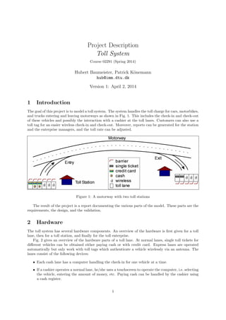
- 1. Project Description Toll System Course 02291 (Spring 2014) Hubert Baumeister, Patrick K¨onemann hub@imm.dtu.dk Version 1: April 2, 2014 1 Introduction The goal of this project is to model a toll system. The system handles the toll charge for cars, motorbikes, and trucks entering and leaving motorways as shown in Fig. 1. This includes the check-in and check-out of these vehicles and possibly the interaction with a cashier at the toll lanes. Customers can also use a toll tag for an easier wireless check-in and check-out. Moreover, reports can be generated for the station and the enterprise managers, and the toll rate can be adjusted. Figure 1: A motorway with two toll stations The result of the project is a report documenting the various parts of the model. These parts are the requirements, the design, and the validation. 2 Hardware The toll system has several hardware components. An overview of the hardware is first given for a toll lane, then for a toll station, and finally for the toll enterprise. Fig. 2 gives an overview of the hardware parts of a toll lane. At normal lanes, single toll tickets for different vehicles can be obtained either paying cash or with credit card. Express lanes are operated automatically but only work with toll tags which authenticate a vehicle wirelessly via an antenna. The lanes consist of the following devices: • Each cash lane has a computer handling the check-in for one vehicle at a time. • If a cashier operates a normal lane, he/she uses a touchscreen to operate the computer, i.e. selecting the vehicle, entering the amount of money, etc. Paying cash can be handled by the cashier using a cash register. 1
- 2. Toll Lane Cash Register Credit Card Reader Printer Single Ticket Reader Toll Lane ComputerTouchscreen Bank ))) ((( Antenna 1) 1) 1) 1) 3) 2) 1) Only normal check-in lane 2) Only normal check-out lane 3) Only express lane (check-in and check-out) Barrier 1,2,3) 1) Figure 2: The hardware of the toll lanes • An indicator showing whether a normal toll lane accepts cash (i.e. a cashier operates the lane). • Every normal lane accepts credit cards, independent of whether a cashier operates the lane or not. To this end, a credit card reader is installed for handling credit card payment. • In addition there is a printer on normal lanes for printing the bill which is handed out to the customer at the end of the check-in. • At express lanes, an antenna is used at check-in and check-out to authenticate vehicles wirelessly by their toll tags. The toll is payed monthly. • The software on the computer of each toll lane is, among other things, responsible for handling the check-in and the communication with the bank. This means, it integrates all devices at the toll lane. For checking the validity of a toll tag, it needs to connect to the enterprise server. • Check-out lanes register vehicles when leaving the motorway; the single ticket must be inserted into the single ticket reader, toll tags are registered automatically. • Barriers only open after a vehicle was registered successfully for check-in and check-out respectively. Each station consists of several toll lanes and a station client for the station manager. Fig. 3 shows such a station. Using the station client, the manager can view reports, and access and modify customer data. Each station is connected to an enterprise server which in turn is connected to an enterprise client as shown in Fig 4. There, the manager can access the system, e.g. in order to generate several kind of reports or to change the toll rate. Furthermore, the enterprise server is connected to the Internet via a Web server. 3 Functionality of the system This section introduces the functionality of the toll system. Users of the system are the cashier, the station manager, the enterprise manager, and the customer. The basic functionalities are: check-in (single ticket or toll tag), check-out, buy toll tag, show reports (station and enterprise), change rate, and administration. Note that the bank and the Web server are not part of the modelling task; however, their interfaces need to be modelled. 2
- 3. Toll Lane Toll Station Toll Lane Toll Lane Toll Lane : : Station Server Station Client Figure 3: A station consists of several lanes, a station server, and a station client Toll Station Enterprise Toll Station Toll Station Toll Station : : Enterprise Server Enterprise Client Webserver Figure 4: The enterprise consists of several toll stations, an enterprise server, and an enterprise client 3.1 Check-in The principle of a check-in depends on whether one buys a single ticket or has a toll tag. With a single ticket, the toll is payed on entering the motorway. With a toll tag, the distance travelled on the motorway is used to compute the toll on leaving the motorway. In addition, the amount to be payed depends on the type of vehicle, which can either be a motorbike, a car, or a truck. The two different kinds of check-ins are now described closer: • A single ticket is valid for one trip only (max. 24h) and has a fixed price. Single tickets are available only at normal lanes and can be payed for either with cash or with credit card. Cash payment is only available at lanes which are operated by a cashier; at lanes without a cashier, only credit card payments are possible. • A toll tag is an RFID transponder with a range of a few meters which is used to wirelessly identify the vehicle. A toll tag is bound to one vehicle only. The price is not fixed but depends on the distance travelled on the motorway, i.e. by calculating the distance between the check-in and check-out. Toll tags need to be bought in advanced (cf. Sect. 3.3). 3
- 4. 3.2 Check-out Similar to the check-in, vehicles must pass a toll lane for exiting the motorway. In case of a single ticket, it must be inserted into the single ticket card reader to validate it. If the single ticket is not valid (see below) then a cashier needs to check that case. For a toll tag, the distance between the check-in and check-out in km is taken and multiplied by the price for one km. The sum of tolls incurred in one month is then charged to the owners bank account at the end of each month. A check-out fails in the following cases: • The single ticket is older than 24h or it was already used in a previous check-out. • The toll tag cannot be recognised by the antenna. In case the check-out fails, a cashier decides how to check-out the vehicle, i.e. charging the owner correctly. 3.3 Buy toll tag A toll tag provides an easier and much cheaper way for paying for using the motorway than a single ticket. It can be ordered from the toll system either in the Internet or at any toll station and has a fixed initial price. The toll will then be charged at the end of each month from a bank account. To buy a toll tag, one needs to fill out a form with some personal, vehicle, and bank account infor- mation. The toll tag is then sent via mail to the vehicle owner (this does not need to be modelled). 3.4 Show reports The station manager can query statistical reports for the station from the station client. It should contain information about how many and which type of vehicles performed a check-in/check-out in a freely definable time period. Furthermore, the statistics should include how many single tickets were used and how often toll tags were used. The enterprise manager has to be able to generate reports with the same information for all stations. 3.5 Change rate The enterprise manager should be able to change the toll rate for single tickets as well as for toll tags. Single tickets have a fixed price for a trip, the rate for toll tags is a fixed price per km. The price changes for all stations at once. 3.6 Notifiy Customers The enterprise manager must be able to send notifications (e.g. about planned rate changes) to all costumers via email or mail. 3.7 Administration Cashiers must identify themselves with the system as a cashier (there is no distinction between different cashiers) using the touchscreen. This activates the toll lanes for cash payments. This is of course not necessary for express lanes. Each station has one station manager. The enterprise has just one enterprise manager. Both, station and enterprise managers, need to register with their respective clients (i.e. station managers with the station client and the enterprise manager with the enterprise client). Again, just the two roles are distinguished, an individual user authentication is not required. Remote logins are also not required. 4 Task The task of the project is to create a requirements and design document containing sufficient information for a programmer to implement the system. To make the task more manageable, you should select, after an initial phase of identifying the basic workflows and use cases, 4–6 use cases (4 for a four person group, 4
- 5. 5 for a five person group, and 6 for a six person group). The selection of the use cases should be done according to the priority of the customer (i.e. the owner of the toll system) and should give raise to the basicxs architecture. The component–, detailed class–, and behaviour–design should then be done in a way that these use cases can be realised, which is to be documented with use case realisations. In addition there need to be acceptance tests for each of the selected use cases. The model does not need to take any physical implementation into account. For example that cash register, printer, etc. are actually realised as embedded systems. One should assume that each software component can talk to another component via a standard component protocol, e.g. RMI (Java), .NET, IIOP (CORBA) etc. That is, the programmer chooses the right implementation language for each device and the communication technology between devices. Furthermore, you should abstract away from any concrete user interface representation. Thus the user interface and its implementation is not part of the design. The focus should be on the application layer functionality, that is, the representation of any user interaction as messages to objects. However, it may be helpful to draw sketches of the user interface to get a feeling for the functionality needed in the application layer. The structure of the document shall be: 1. Title page containing the group number and the names and study numbers of the participants 2. Introduction (a) Methodology Used 3. Requirements (a) Domain Analysis (b) Functional Requirements (c) Non-Functional Requirements 4. Acceptance Tests 5. Design (a) Component Design (b) Class Design (c) Behaviour Design 6. Validation (a) Use Case Realisation 7. Conclusion (a) Experience with the project Note that there should not be any appendicies! It is important that I can find the diagrams and texts where I expect them. The report should be uploaded CampusNet using the assignment module; one upload for each project group. The report should be a PDF file with name report xx.pdf, where xx is the group number, e.g. report 01.pdf. It is important that you stick to the naming convention and that you make sure that the filename is all lowercase. 4.1 Section Introduction The introduction should describe the steps actually used to solve the modelling task and why these steps were chosen. For example, were techniques from agile modelling used (which?), were CRC cards used, domain-driven design, explorative modelling, etc.? 5
- 6. 4.2 Section Domain Analysis Create a glossary explaining the notions and terminologies discovered when analysing the domain of the toll system. Create a class diagram of the domain. 4.3 Functional Requirements Describe the basic workflows of the toll system as activity diagrams. Based on the basic workflows and on the problem description, identify the functional requirements using use cases. Create a use case diagram showing all identified use cases. Out of the use cases identified and shown in the use case diagram, select 4–6 use cases (cf. Sect. 4) according to their priority for the customer (who is the owner of the toll system). The selected use cases form the basis of the remaining sections, e.g. the design and the validation sections. For the selected use cases create detailed use case descriptions according to the following template: 1. Use Case Name 2. Summary 3. Actors 4. Preconditions 5. Basic course of events 6. Alternative paths 7. Postconditions 8. Notes 9. Author 4.4 Section Acceptance Tests Define for each use case selected in Sect. 4.3 sufficient Fit1 tests to test the implementation of the design. 4.5 Section Design This section contains the design of the system. It is only necessary to create a design realizing the use cases identified in Sect. 4.3. Explain any non-trivial design decision that you make, and state any assumptions that you make.2 4.6 Section Component Design Define the components of the system with their ports (i.e., a port is a set of required and provided interfaces). For each provided interface of a port provide the protocol state machine. For hardware components that one would buy off the shelf, like antenna, ticket reader, barrier, . . . , it is sufficient to provide the ports with their protocol state machines without going into the details of their possible implementation. 4.7 Section Class Design Define the classes used to implement the components. Some components can be implemented as a single classes; other components can be implemented by a set of classes. Provide any necessary class invariants using OCL constraints. Specify the contracts of non-trivial operations using OCL constraints (pre:/post:). Describe each class, their interaction, and the contract of operations also using informal text. Note that for hardware components that one would buy off the shelf, like antenna, ticket reader, barrier, . . . , it is not necessary to detail their implementation (cf. Sect. 4.6). 1fit.c2.com 2You may want to check these assumption with me first before assuming them. 6
- 7. 4.8 Section Behaviour Design Describe the behaviour of each non-trivial class using object life cycle state machines. 4.9 Section Use Case Realisation Show how the system realizes the use cases selected in Sect. 4.3 using interaction diagrams. Show that each of the scenarios defined by the use cases is executed using the design of the system by providing sequence- or communication diagrams for each scenario. Choose the appropriate type of interaction diagram for a scenario. 4.10 Experience with the project This section should cotain the experiences with the project. For example, what was learned, what are the things you can improve next time, and what you did make good this time. (This will not be graded!) 4.11 Who did what in the project It is important that with each section / subsection it is marked who is responsible for that part of the text. There can be at most two persons responsible for each part of the text. Make sure that each member of the group does something of each task! Everybody should have read the project and be able to explain each part of the model in the project presentation. 4.12 Use of other material than your own Please make sure that you correctly cite text and ideas from other sources, i.e. by using quotes and providing a reference to the source. More details can be found in section 3.9 in the study handbook (http://shb.dtu.dk/Default.aspx?documentid=3086&Language=en-GB&lg=&version=2013/2014). 4.13 What needs to be delivered? The project report is to be uploaded before as PDF using the assingment module on CampusNet. It is not necessary to deliver a printed copy of the report. Look in Sect. 4 for details of the naming convention. 5 Criteria for Evaluation 1. Correct use of UML diagrams and OCL constraints 2. Understandability of the design. Could a programmer take the design and implement it without many further inquiries? 3. Are the use case realisations correct? That is, (a) all messages in the interaction diagrams appear in the respective interfaces of the class (b) all message sequences are admissible according to the behaviour specification (c) all messages are admissible according to the protocol state machines (PSM) 4. Is the detailed class diagram an implementation of the component diagram (with ports and protocol state machines)? That is, (a) all provided interfaces are implemented by a class (b) the PSM only uses messages belonging to the provided interface as events (e.g. [pre] op / [post]) (c) The interactions defined by the PSM must be possible in the implementation 7
- 8. • if the implementation is a state machine, then it must be a refinement of the PSM, that is, it must be able to receive an event when the PSM is able to receive an event (it can of course receive more events) and it must only send messages defined by the PSM (through the port of the PSM) (it can be less, but not more) 5. Object life cycle state machines are correct, i.e. (a) The events in the transition of the state machine, i.e. event [guard] / effect, are operations of corresponding class. (b) Transitions have an effect, e.g. assignments to attributes e.t.c. and sending messages to other objects 6. Are all design decisions documented? Are all assumptions documented? 7. Appropriate abstraction level of the design. Does the design contain any implementation specific details that could be expressed using UML models in a different way? For example, the elements of an enumeration are expressed using constants instead of using the enumeration datatype provided by the UML. Another example is using an attribute with an accessor operation that should be better expressed as an association. For example, a company could have an attribute employees of type Vector and an operation getEmployees(), returning all its employees, or an association from class Company to class Person representing the employees of the company (cf. Fig. 5). Figure 5: Discouraged and encourage representation of the employee relationship between company and person. 8