SlideShare una empresa de Scribd logo
1 de 12
Descargar para leer sin conexión
Shackles.fm Page 25 Wednesday, February 1, 2006 11:43 AM


                                                           Shackles
                                         s e l k c a h S


                                                                           Shackles


          Copyright © 2006 The Crosby Group, Inc.                     57
          All Rights Reserved
Shackles_C&E.fm Page 58 Tuesday, January 31, 2006 5:12 PM


                                                                           Shackles
                                                                  What It Takes To Be
                                                                                                                                                          G-2130
        G-209
                                    “Crosby Or Equal”
    DESIGN                                                                         COMPETITION                                            CROSBY
    The theoretical reserve capability of carbon shackles
    should be as a minimum 5 to 1, and alloy shackles a               Ask: What is Working Load Limit and design Crosby carbon shackles have the highest
    minimum of 5 to 1*. Known as the DESIGN FACTOR, it                factor for shackles?                          design factor (6 to 1) in the industry.
    is usually computed by dividing the catalog ultimate                                                            All of Crosby’s design factors are
    load by the working load limit. The ultimate load is the          Ask: Is deformation upon overloading a criti- documented. Crosby purchases only
    average load or force at which the product fails or no            cal consideration in their design?            special bar forging quality steel with
    longer supports the load. The working load limit is                                                             special cleanliness and guaranteed
    the maximum mass or force which the product is                    Ask: Do they jeopardize other properties by   hardenability. All material chemistry is
    authorized to support in general service. The design              having hardness high in order to increase     independently verified prior to
    factor is generally expressed as a ratio such as 5 to 1.          working load or design factor?                manufacturing. The design of Crosby
    Also important to the design of shackles is the selection                                                       shackles assure that strength,
    of proper steel to support fatigue, ductility and impact                                                        ductility and fatigue
    properties.                                                                                                     properties are met.


    CLOSED DIE FORGED                                                 Ask: Are their shackles closed die forged with  Each shackle is closed die forged.
    The proper performance of premium shackles depends                close tolerance pin holes?                      Closed die forging produces consistent
    on good manufacturing techniques that include proper                                                              dimensions. Close tolerance holes and
    forging and accurate machining. Closed die forging of             Ask: Do their shackles have good fatigue life? concentric pins with good surface finishes
    shackles assures clear lettering, superior grain flow, and                                                        are provided by Crosby and are proven to
    consistent dimensional accuracy. A closed die forged              Ask: Do their shackles have a fatigue life that provide improved fatigue life in actual
    bow allows for an increased cross section that, when              meets the new world standards?                  use. Crosby shackles are fatigue rated as
    coupled with quench and tempering, enhances strength                                                              well as load rated.
    and ductility. Closed die bow forgings combined with              Many forge bows, utilizing an open
    close tolerance pin holes assures good fatigue life. Close        die forging process which allows for
    pin to hole tolerance has been proven to be critical for          inconsistent dimensional accuracy and
    good fatigue life, particularly with screw pin shackles.          increased pin hole clearance, thus
                                                                      jeopardizing the fatigue life of the shackle
                                                                      in actual use.

    QUENCHED AND TEMPERED                                             Ask: Are their bows and pins quenched and    All Crosby shackle bows and pins are
    Quench and tempering assures the uniformity of                    tempered?                                    quenched and tempered, which enhances
    performance and maximizes the properties of the steel.                                                         their performance under cold tempera-
    This means that each shackle meets its rated strength             Ask: If not, are they willing to accept the  tures and adverse field conditions.
    and has required ductility, toughness, impact and                 increased risk of inconsistency?             Crosby’s Quenched and Tempered carbon
    fatigue properties. The requirements of your job                                                               shackles are recommended for all critical
    demand this reliability and consistency. This quench              Ask: If not, why are they willing to accept  applications including overhead lifting.
    and tempering process develops a tough material that              inferior impact, toughness, and product      Alloy shackles are recommended when
    reduces the risk of brittle, catastrophic failure. The            deformation?                                 specific dimensional requirements dictate
    shackle bow will deform if overloading occurs,                                                                 a size that requires higher working load
                                                                      Ask: Why do many manufacturers not           limits. Crosby’s Quenched and Tempered
    giving warning before ultimate failure.                           recommend non-heat treated shackles for      shackles provide the tensile strength,
                                                                      overhead lifting?                            ductility, impact and fatigue properties
                                                                      Ask: Why do some recommend Quench and        that are essential if they are to perform
                                                                      Tempering for alloy but not carbon grades?   time after time in adverse conditions.
                                                                                                                   These properties assure that the inspection
                                                                      Many normalize the shackle bows. As a        criteria set forth by ANSI will
                                                                      result, desired properties are not achieved. effectively monitor the ability
                                                                      A few even provide bows in an “as            of the shackles to
                                                                      forged” condition, resulting in the          continue in service.
                                                                      possibility of brittle failure.

    IDENTIFICATION AND APPLICATION                                    Ask: Do they have an active traceability            Crosby forges “Crosby” or “CG”, the
    INFORMATION                                                       system used in manufacturing?                       Working Load Limit, and the Product
    The proper application of shackles requires that the                                                                  Identification Code (PIC) into each bow
    correct type and size of shackle be used. The shackle’s           Ask: Is the material chemistry independently        and pin of its full line of screw pin, round
    working load limit, its size, a traceability code and the         verified?                                           pin, and bolt type anchor and chain
    manufacturer’s name should be clearly and boldly                                                                      shackles.
    marked in the bow. Traceability of the material                   Ask: What training support is provided?             Seminars conducted by Crosby provide
    chemistry and properties is essential for total                                                                       training on the proper use of shackles.
    confidence in the product. Material chemistry                                                                         Crosby training packets, supplied free to
    should be independently verified prior to                                                                             attendees of Crosby seminars, provide
    manufacturing.                                                                                                        training materials needed
                                                                                                                          to explain the proper
                                                                                                                          use of shackles.

   * G-2160 Wide Body Shackles are metric rated at 5 to 1. G-2140 shackles, 200 ton and above, are rated at 4 to 1 in short tons.


                              Remember, “When buying Crosby, you’re buying more than product, you’re buying Quality.”
   58                                                                                              Copyright © 2006 The Crosby Group, Inc.
                                                                                                                        All Rights Reserved
Shackles_C&E.fm Page 59 Tuesday, January 31, 2006 5:13 PM


                                                            Crosby Value Added

           • Charpy impact properties: Crosby’s Quenched and Tempered shackles have enhanced impact properties for greater
             toughness at all temperatures. If requested at the time of order, Crosby can provide Charpy impact properties.
           • Fatigue properties: Fatigue properties are available for 1/3 to 55 metric ton shackles. These Crosby shackles are fatigue rated
             to 20,000 cycles at 1-1/2 times the Working Load Limit.
           • Ductility properties: Typical ductility properties are available for all sizes upon special request.


                                                                                                                                                   Shackles
           • Hardness levels and material tensile strengths: Typical values are available for all sizes of shackles, and actual values can


                                                                                                                                                   Shackles
             be furnished if requested at the time of order.
           • Proof Testing: If requested at the time of order, shackles can be furnished proof tested with certificates.
           • Mag Certification: If requested at the time of order, shackles can be Mag inspected with certificates.
           • Certification: Certification to World Class Standards is available upon special request at the time of order; American Bureau
             of Shipping, Lloyds Register of Shipping, Det Norske Veritas, American Petroleum Institute, RINA, Nuclear Regulatory
             Commission, and several other world wide standards.
           • Applications: Round Pin Shackles can be used in tie down, towing, suspension or lifting applications where the load is strictly
             applied in-line. Screw Pin Shackles can be used in any application where a round pin shackle is used. In addition, screw pin
             shackles can be used for applications involving side-loading circumstances. Reduced working load limits are required for
             side-loading applications. Bolt-Type Shackles can be used in any application where round pin or screw pin shackles are used.
             In addition, they are recommended for permanent or long-term installations and where the load may slide on the shackle
             pin causing the pin to rotate.
           • Material analysis: Crosby can provide certified material (mill) analysis for each production lot, traceable by the Product
             Identification Code (PIC). Crosby, through its own laboratory, verifies the analysis of each heat of steel. Crosby purchases
             only special bar forging quality steel with specific cleanliness requirements and guaranteed hardenability.
           • Field inspection: Written instructions for visual, magnaflux, and dye penetrant inspection of shackles are available from
             Crosby. In addition, acceptance criteria and repair procedures for shackles are available.
           • QUIC-CHECK®: Shackles incorporate two marking indicators forged into the shackle bow at 45° angles from vertical. These
             are utilized to quickly check the approximate angle of a two-legged hitch or quickly check the angle of a single leg hitch when
             the shackle pin is secured and the pull of the load is off vertical or side loaded, thus requiring a reduction in the working load
             limit of the shackle.


          G-209 S-209                                       G-213 S-213                              G-2130 S-2130
          Screw pin anchor                                  Round pin anchor                         Bolt-type anchor
          shackles meet the                                 shackles meet the                        shackles meet the
          performance                                       performance                              performance
          requirements of                                   requirements of                          requirements of
          Federal Specification                             Federal Specification                    Federal Specification
          RR-C-271D Type IVA,                               RR-C-271D Type IVA,                      RR-C-271D Type IVA,
          Grade A, Class 2,                                 Grade A, Class 1,                        Grade A, Grade A,
          except for those                                  except for those                         Class 3, except for
          provisions required of                            provisions required of                   those provisions
          the contractor.                                   the contractor.                          required of the
                                                                                                     contractor.


          G-210 S-210                                       G-215 S-215                              G-2150 S-2150
          Screw pin chain                                   Round pin chain                          Bolt-type chain
          shackles meet the                                 shackles meet the                         shackles meet the
          performance                                       performance                              performance
          requirements of                                   requirements of                          requirements of
          Federal Specification                             Federal Specification                    Federal Specification
          RR-C-271D Type IVB,                               RR-C-271D Type IVB,                      RR-C-271D Type IVB,
          Grade A, Class 2,                                 Grade A, Class 1,                        Grade A, Class 3,
          except for those                                  except for those                         except for those
          provisions required of                            provisions required of                   provisions required of
          the contractor.                                   the contractor.                          the contractor.


          Copyright © 2006 The Crosby Group, Inc.                                                                                             59
          All Rights Reserved
Crosby® Round Pin Shackles

         ROUND PIN                                                          • Capacities 1/2 thru 35 metric tons.                                                                                           ROUND PIN
          ANCHOR                                                            • Forged - Quenched and Tempered, with alloy pins.                                                                                CHAIN
         SHACKLES                                                           • Working Load Limit permanently shown on every shackle.                                                                        SHACKLES
                                                                            • Hot Dip galvanized or Self Colored.
                                                                            • Fatigue rated.
                                                                            • Shackles can be furnished proof tested with certificates to designated
                                                                              standards, such as ABS, DNV, Lloyds, or other certification. Charges
                                                                              for proof testing and certification available when requested at the time
                                                                              of order.
                                                                            • Shackles are Quenched and Tempered and can meet DNV impact
                                                                              requirements of 42 joules at -20 degree C.
           G-213 S-213                                                      • Look for the Red Pin® . . . the mark of genuine Crosby quality.
                        s e l k c a h S   n i P   d n u o R   ®   y b s o r C                                                                                                                                   G-215 S-215
Round pin anchor shackles meet the
performance requirements of Federal                                                                                                                                                                Round pin chain shackles meet the
                                                                                                                                                                                                   performance requirements of Federal
Specification RR-C-271D Type IVA,
Grade A, Class 1, except for those provi-                                                                                                                                                          Specification RR-C-271D Type IVB,
                                                                                                                                                                                                   Grade A, Class 1, except for those provi-
sions required of the contractor. For
additional information, see page 361.                                                                                                                                                              sions required of the contractor. For
                                                                                                                                                                                                   additional information, see page 361.


                                                                                          Working                                                                                   Dimensions                                   Tolerance
                                                                                Nominal    Load                  Stock No.
                                                                                                       SN213Header                            Weight                                   (mm)                                         +/-
                                                                                  Size     Limit                                               Each
                                                                                  (in.)     (t) *    G-213                          S-213      (kg.)     A      B      C      D       E      F       G      H       N      P      C      A
                                                                                   1/4      1/2     1018017                        1018026      .06     11.9   7.85   28.7   6.35    19.8   15.5    32.5   46.7    34.0   6.35   1.50   1.50
                                                                                 5/16       3/4     1018035                        1018044      .08     13.5   9.65   31.0   7.85    21.3   19.1    37.3   53.0    40.4   7.85   1.50   1.50
                                                                                   3/8        1     1018053                        1018062      .13     16.8   11.2   36.6   9.65    26.2   23.1    45.2   63.0    47.2   9.65   3.30   1.50
                                                                                 7/16      1-1/2    1018071                        1018080      .17     19.1   12.7   42.9   11.2    29.5   26.9    51.5   74.0    54.0   11.2   3.30   1.50
                                                                                   1/2        2     1018099                        1018106      .32     20.6   16.0   47.8   12.7    33.3   30.2    58.5   83.5    60.5   12.7   3.30   1.50
                                                                                   5/8     3-1/4    1018115                        1018124      .68     26.9   19.1   60.5   16.0    42.9   38.1    74.5   106     74.0   17.5   3.30   1.50
                                                                                   3/4     4-3/4    1018133                        1018142     1.05     31.8   22.4   71.5   19.1    51.0   46.0    89.0   126     87.0   20.6   6.35   1.50
                                                                                   7/8     6-1/2    1018151                        1018160     1.58     36.6   25.4   84.0   22.4    58.0   53.0    102    148     96.5   24.6   6.35   1.50
                                                                                    1      8-1/2    1018179                        1018188     2.27     42.9   28.7   95.5   25.4    68.5   60.5    119    167     115    26.9   6.35   1.50
                                                                                 1-1/8     9-1/2    1018197                        1018204     3.16     46.0   31.8   108    28.7    74.0   68.5    131    190     130    31.8   6.35   1.50
                                                                                 1-1/4       12     1018213                        1018222     4.42     51.5   35.1   119    32.8    82.5   76.0    146    210     140    35.1   6.35   1.50
                                                                                 1-3/8     13-1/2   1018231                        1018240     6.01     57.0   38.1   133    36.1    92.0   84.0    162    233     156    38.1   6.35   3.30
                                                                                 1-1/2       17     1018259                        1018268     7.82     60.5   41.4   146    39.1    98.5   92.0    175    254     165    41.1   6.35   3.30
                                                                                 1-3/4       25     1018277                        1018286     13.4     73.0   51.0   178    46.7    127    106     225    313     197    57.0   6.35   3.30
                                                                                    2        35     1018295                        1018302     20.8     82.5   57.0   197    53.0    146    122     253    348     222    61.0   6.35   3.30


         G-213 S-213
                                                                                          Working                                                                                   Dimensions                                   Tolerance
                                                                                Nominal    Load                                Stock No.
                                                                                                                     SN215Header               Weight                                  (mm)                                         +/-
                                                                                 Size      Limit                                                Each
                                                                                  (in.)      (t)*    G-215                           S-215      (kg)      A       B      C      D        E      F         G        K       N      G      A
                                                                                   1/4       1/2    1018810                         1018829      .05     11.9    7.85   6.35   6.35     24.6   15.5      22.4     40.4    34.0   1.50   1.50
                                                                                 5/16        3/4    1018838                         1018847      .08     13.5    9.65   7.85   7.85     29.5   19.1      26.2     48.5    40.4   1.50   1.50
                                                                                   3/8        1     1018856                         1018865      .11     16.8    11.2   9.65   9.65     35.8   23.1      31.8     58.5    47.2   3.30   1.50
                                                                                 7/16       1-1/2   1018874                         1018883      .18     19.1    12.7   11.2   11.2     41.4   26.9      36.6     67.5    54.0   3.30   1.50
                                                                                   1/2        2     1018892                         1018909      .23     20.6    16.0   12.7   12.7     46.0   30.2      41.4     77.0    60.5   3.30   1.50
                                                                                   5/8      3-1/4   1018918                         1018927      .55     26.9    19.1   15.7   16.0     58.5   38.1      51.0     95.5    74.0   3.30   1.50
                                                                                   3/4      4-3/4   1018936                         1018945      .91     31.8    22.4   20.6   19.1     70.0   46.0      60.5     115     87.0   6.35   1.50
                                                                                   7/8      6-1/2   1018954                         1018963     1.49     36.6    25.4   24.6   22.4     81.0   53.0      71.5     135     96.5   6.35   1.50
                                                                                    1       8-1/2   1018972                         1018981     2.15     42.9    28.7   25.4   25.4     93.5   60.5      81.0     151     115    6.35   1.50
                                                                                 1-1/8      9-1/2   1018990                         1019007     2.86     46.0    31.8   31.8   28.7     103    68.5      91.0     172     130    6.35   1.50
                                                                                 1-1/4       12     1019016                         1019025     4.08     51.5    35.1   35.1   31.8     115    76.0      100      191     140    6.35   3.30
                                                                                 1-3/8     13-1/2   1019034                         1019043     5.44     57.0    38.1   38.1   35.1     127    84.0      111      210     156    6.35   3.30
                                                                                 1-1/2       17     1019052                         1019061     7.33     60.5    41.4   41.1   38.1     137    92.0      122      230     165    6.35   3.30
                                                                                 1-3/4       25     1019070                         1019089     13.6     73.0    51.0   54.0   44.5     162    106       146      279     197    6.35   3.30
                                                                                    2        35     1019098                         1019105     19.6     82.5    57.0   51.0   53.3     184    122       172      312     222    6.35   3.30
                                                                            * NOTE: Maximum Proof Load is 2.0 times the Working Load Limit. Minimum Ultimate Strength is 6 times the
                                                                              Working Load Limit. For Working Load Limit reduction due to side loading applications, see page 68.


         G-215 S-215

60                                                                                                                                                                                  Copyright © 2006 The Crosby Group, Inc.
                                                                                                                                                                                                         All Rights Reserved
Crosby® Screw Pin Shackles

         SCREW PIN                                                         •    Capacities 1/3 thru 55 metric tons.                                                SCREW PIN
          ANCHOR                                                           •    Forged - Quenched and Tempered, with alloy pins.                                       CHAIN
         SHACKLES                                                          •    Working Load Limit permanently shown on every shackle.                             SHACKLES


                                                                                                                                                                                                                                                      Shackles
                                                                           •    Hot Dip galvanized or Self Colored.
                                                                           •    Fatigue rated.
                                                                           •    Shackles can be furnished proof tested with certificates to designated
                                                                                standards, such as ABS, DNV, Lloyds, or other certification. Charges
                                                                                for proof testing and certification available when requested at the time
                                                                                of order.
                                                                           •    Shackles are Quenched and Tempered and can meet DNV impact
                                                                                requirements of 42 joules at -20 C.
                                                                           •    Sizes 1/2t - 25t meet the performance requirements of EN13889:2003
                                                                           •    Crosby products meet or exceed all requirements of ASME B30.26                       G-210 S-210
           G-209 S-209                                                          including identification, ductility, design factor, proof load and       Screw pin chain shackles meet the
Screw pin anchor shackles meet the                                              temperature requirements. Importantly, Crosby products meet other performance requirements of Federal
performance requirements of Federal                                             critical performance requirements including fatigue life, impact         Specification RR-C-271D, Type IVB,
Specification RR-C-271D Type IVA,
Grade A, Class 2, except for those provi-
                                                                                properties and material traceability, not addressed by ASME B30.26. Grade A, Class 2, except for those provi-
                                                                                                                                                         sions required of the contractor. For
sions required of the contractor. For     •                                     Look for the Red Pin® . . . the mark of genuine Crosby quality.          additional information, see page 361.
additional information, see page 361.
                       s e l k c a h S   n i P   w e r c S   ®   y b s o r C


                                                                                         Working                                                                                  Dimensions                                       Tolerance
                                                                               Nominal    Load                  Stock No.
                                                                                                      SN209Header                           Weight                                   (mm)                                             +/-
                                                                                Size      Limit                                              Each
                                                                                 (in.)     (t) *    G-209                          S-209     (kg)     A      B      C      D      E      F      G      H       L      M      P      C      A
                                                                                3/16       1/3     1018357                           -        .03    9.65   6.35   22.4   4.85   15.2   14.2   24.9   37.3    4.06   28.4   4.85   1.50   1.50
                                                                                  1/4      1/2     1018375                        1018384     .05    11.9   7.85   28.7   6.35   19.8   15.5   32.5   46.7    4.85   35.1   6.35   1.50   1.50
                                                                                5/16       3/4     1018393                        1018400     .09    13.5   9.65   31.0   7.85   21.3   19.1   37.3   53.0    5.60   42.2   7.85   3.30   1.50
                                                                                  3/8        1     1018419                        1018428     .14    16.8   11.2   36.6   9.65   26.2   23.1   45.2   63.0    6.35   51.5   9.65   3.30   1.50
                                                                                7/16      1-1/2    1018437                        1018446     .17    19.1   12.7   42.9   11.2   29.5   26.9   51.5   74.0    7.85   60.5   11.2   3.30   1.50
                                                                                  1/2        2     1018455                        1018464     .33    20.6   16.0   47.8   12.7   33.3   30.2   58.5   83.5    9.65   68.5   12.7   3.30   1.50
                                                                                  5/8     3-1/4    1018473                        1018482     .62    26.9   19.1   60.5   16.0   42.9   38.1   74.5   106     11.2   85.0   17.5   6.35   1.50
                                                                                  3/4     4-3/4    1018491                        1018507    1.07    31.8   22.4   71.5   19.1   51.0   46.0   89.0   126     12.7   101    20.6   6.35   1.50
                                                                                  7/8     6-1/2    1018516                        1018525    1.64    36.6   25.4   84.0   22.4   58.0   53.0   102    148     12.7   114    24.6   6.35   1.50
                                                                                   1      8-1/2    1018534                        1018543    2.28    42.9   28.7   95.5   25.4   68.5   60.5   119    167     14.2   129    26.9   6.35   1.50
                                                                                1-1/8     9-1/2    1018552                        1018561    3.36    46.0   31.8   108    29.5   74.0   68.5   131    190     16.0   142    31.8   6.35   1.50
                                                                                1-1/4       12     1018570                        1018589    4.31    51.5   35.1   119    32.8   82.5   76.0   146    210     17.5   156    35.1   6.35   1.50
                                                                                1-3/8     13-1/2   1018598                        1018605    6.14    57.0   38.1   133    36.1   92.0   84.0   162    233     19.1   174    38.1   6.35   3.30
                                                                                1-1/2       17     1018614                        1018623    7.80    60.5   41.4   146    39.1   98.5   92.0   175    254     20.6   187    41.1   6.35   3.30
                                                                                1-3/4       25     1018632                        1018641    12.6    73.0   51.0   178    46.7   127    106    225    313     25.4   231    57.0   6.35   3.30
                                                                                   2        35     1018650                        1018669    20.4    82.5   57.0   197    53.0   146    122    253    348     31.0   263    61.0   6.35   3.30
                                                                                2-1/2       55     1018678                        1018687    38.9    105    70.0   267    69.0   184    145    327    453     35.1   330    79.5   6.35   6.35


         G-209 S-209
                                                                                         Working                                                                                    Dimensions                                     Tolerance
                                                                               Nominal    Load                                Stock No.
                                                                                                                    SN210Header              Weight                                    (mm)                                            +/-
                                                                                Size      Limit                                               Each
                                                                                 (in.)     (t)*      G-210                          S-210     (kg)      A      B      C       D      E      F      G          K       L      M      G      A
                                                                                  1/4      1/2      1019150                        1019169     .05     11.9   7.85   6.35    6.35   24.6   15.5   22.4       40.4    4.85   35.1   1.50   1.50
                                                                                5/16       3/4      1019178                        1019187     .08     13.5   9.65   7.85    7.85   29.5   19.1   26.2       48.5    5.60   42.2   1.50   1.50
                                                                                  3/8       1       1019196                        1019203     .13     16.8   11.2   9.65    9.65   35.8   23.1   31.8       58.5    6.35   51.5   3.30   1.50
                                                                                7/16      1-1/2     1019212                        1019221     .20     19.1   12.7   11.2    11.2   41.4   26.9   36.6       67.5    7.85   60.5   3.30   1.50
                                                                                  1/2       2       1019230                        1019249     .27     20.6   16.0   12.7    12.7   46.0   30.2   41.4       77.0    9.65   68.5   3.30   1.50
                                                                                  5/8     3-1/4     1019258                        1019267     .57     26.9   19.1   15.7    16.0   58.5   38.1   51.0       95.5    11.2   85.0   3.30   1.50
                                                                                  3/4     4-3/4     1019276                        1019285    1.20     31.8   22.4   20.6    19.1   70.0   46.0   60.5       115     12.7   101    6.35   1.50
                                                                                  7/8     6-1/2     1019294                        1019301    1.43     36.6   25.4   24.6    22.4   81.0   53.0   71.5       135     12.7   114    6.35   1.50
                                                                                   1      8-1/2     1019310                        1019329    2.15     42.9   28.7   25.4    25.4   93.5   60.5   81.0       151     14.2   129    6.35   1.50
                                                                                1-1/8     9-1/2     1019338                        1019347    3.06     46.0   31.8   31.8    28.7   103    68.5   91.0       172     16.0   142    6.35   1.50
                                                                                1-1/4       12      1019356                        1019365    4.11     51.5   35.1   35.1    31.8   115    76.0   100        191     17.5   156    6.35   3.30
                                                                                1-3/8     13-1/2    1019374                        1019383    5.28     57.0   38.1   38.1    35.1   127    84.0   111        210     19.1   174    6.35   3.30
                                                                                1-1/2       17      1019392                        1019409    7.23     60.5   41.4   41.1    38.1   137    92.0   122        230     20.6   187    6.35   3.30
                                                                                1-3/4       25      1019418                        1019427    12.1     73.0   51.0   54.0    44.5   162    106    146        279     25.4   231    6.35   3.30
                                                                                   2        35      1019436                        1019445    19.2     82.5   57.0   60.0    51.0   184    122    172        312     31.0   263    6.35   3.30
                                                                                2-1/2       55      1019454                        1019463    32.5     105    70.0   66.5    66.5   238    145    203        377     35.1   330    6.35   6.35
                                                                           * NOTE: Maximum Proof Load is 2.0 times the Working Load Limit. Minimum Ultimate Strength is 6 times the
                                                                             Working Load Limit. For Working Load Limit reduction due to side loading applications, see page 68.

         G-210 S-210
Copyright © 2006 The Crosby Group, Inc.                                                                                                                                                                                                          61
All Rights Reserved
Crosby® Alloy Screw Pin Shackles

              G-209A                                                                        • Capacities 2 thru 21 metric tons.
                                                                                            • Forged Alloy Steel - Quenched and Tempered, with alloy pins.
                                                                                            • Working Load Limit permanently shown on every shackle.
                                                                                            • Hot Dip Galvanized.
                                                                                            • Crosby products meet or exceed all requirements of ASME B30.26
                                                                                              including identification, ductility, design factor, proof load and
                                                                                              temperature requirements. Importantly, Crosby products meet
                                                                                              other critical performance requirements including fatigue life, impact
                                                                                              properties and material traceability, not addressed by ASME B30.26.
                                                                                            • Shackles can be furnished proof tested with certificates to
                                                                                              designated standards, such as ABS, DNV, Lloyds, or other
Screw pin anchor shackles meet the                                                            certification. Charges for proof testing and certification available
performance requirements of Federal                                                           when requested at the time of order.
Specification RR-C-271D Type IVA,
                    s e l k c a h S   n i P   w e r c S   y o l l A   ®   y b s o r C


Grade B, Class 2, except for those provi-
sions required of the contractor. For
additional information, see page 361.


G-209A
Crosby® Alloy Screw Pin Shackles
  Nominal        Working                                                     SN209AHeader         Weight                                    Dimensions                                    Tolerance
   Size         Load Limit                                 G-209-A                                 Each                                        (mm)                                           +/-
    (in.)           (t)*                                  Stock No.                                (kg)      A      B      C      D      E       F     G      H      L      M      P      C        A
     3/8             2                                     1017450                                  .14     16.8   11.2   36.6   9.65   26.2    23.1  45.2   63.5   6.35   51.5   9.65   3.30     1.50
   7/16            2-2/3                                   1017472                                  .17     19.1   12.7   42.9   11.2   29.5    26.9  51.5   74.0   7.85   60.5   11.2   3.30     1.50
     1/2           3-1/3                                   1017494                                  .29     20.6   16.0   47.8   12.7   23.3    30.2  58.5   83.5   9.65   68.5   12.7   3.30     1.50
     5/8             5                                     1017516                                  .63     26.9   19.1   60.5   16.0   42.9    38.1  74.5   106    11.2   85.0   17.5   3.30     1.50
     3/4             7                                     1017538                                 1.02     31.8   22.4   71.5   19.1   51.0    46.0  89.0   126    12.7   101    20.6   6.35     1.50
     7/8           9-1/2                                   1017560                                 1.53     36.6   25.4   84.0   22.4   58.0    53.0  102    148    12.7   114    24.6   6.35     1.50
      1           12-1/2                                   1017582                                 2.41     42.9   28.7   95.5   25.4   68.5    60.5  119    167    14.2   129    26.9   6.35     1.50
   1-1/8            15                                     1017604                                 3.09     46.0   31.8   108    29.5   74.0    68.5  131    190    16.0   142    31.8   6.35     1.50
   1-1/4            18                                     1017626                                 4.31     51.5   35.1   119    32.8   82.5    76.0  146    210    17.5   156    35.1   6.35     1.50
   1-3/8            21                                     1017648                                 6.01     57.0   38.1   133    36.1   92.0    84.0  162    233    19.1   174    38.1   6.35     3.30
* Maximum Proof Load is 2 times the Working Load Limit (metric tons).
  Minimum Ultimate Load is 4.5 times Working Load Limit based on Metric tons.
  For Working Load Limit reduction due to side loading applications, see page 68.


62                                                                                                                                                           Copyright © 2006 The Crosby Group, Inc.
                                                                                                                                                                                  All Rights Reserved
Crosby® Bolt Type Shackles

         BOLT TYPE                         • Working Load Limit permanently shown on every shackle.                           BOLT TYPE
                                             Capacities 1/3 thru 150 metrics tons.
          ANCHOR                                                                                                                   CHAIN
                                           • Forged — Quenched and Tempered, with alloy pins.
         SHACKLES                                                                                                              SHACKLES


                                                                                                                                                                                                              Shackles
                                           • Hot Dip galvanized or Self Colored.
                                           • Fatigue rated.
                                           • Crosby products meet or exceed all requirements of ASME B30.26
                                             including identification, ductility, design factor, proof load and
                                             temperature requirements. Importantly, Crosby products meet other
                                             critical performance requirements including fatigue life, impact
                                             properties and material traceability, not addressed by ASME B30.26.
                                           • Sizes 1/2t - 25t meet the performance requirements of EN13889:2003
                                           • Shackles 55 metric tons and smaller can be furnished proof tested with
          G-2130 S-2130                      certificates to designated standards, such as ABS, DNV, Lloyds, or                G-2150 S-2150
Bolt Type Anchor shackles with thin          other certification when requested at time of order.                   Bolt Type Chain shackles. Thin hex head
head bolt - nut with cotter pin. Meets the                                                                          bolt - nut with cotter pin. Meets the
performance requirements of Federal • Shackles 85 metric tons and larger can be provided as follows.                performance requirements of Federal
Specification RR-C-271D Type IVA,                                                                                                                                   Specification RR-C271D Type IVB, Grade
                                                                                      • Non Destructive Tested
Grade A, Class 3, except for those provi-                                                                                                                           A, Class 3, except for those provisions
                                                                                      • Serialized Pin and Bow
sions required of the contractor. For                                                                                                                               required of the contractors. For
                                                                                      • Material Certification (Chemical) Certification must be
additional information, see page 361.                                                                                                                               additional information, see page 361.
                                                                                        requested at time of order.
                                                                            • Look for the Red Pin® . . . the mark of genuine Crosby quality.
                        s e l k c a h S   e p y T   t l o B   ®   y b s o r C


                                                                                Nominal    Working                         Weight                          Dimensions                          Tolerance
                                                                                 Size     Load Limit       Stock No.
                                                                                                          SN2130Header
                                                                                                                            Each                              (mm)                                 +/-
                                                                                  (in.)       (t) *    G-2130    S-2130     (kg)     A      B      C      D     E   F      H      L      N      C      A
                                                                                 3/16        1/3‡      1019464      -        .03    9.65   6.35   22.4   4.85 15.2 14.2   37.3   24.9   4.85   1.50 1.50
                                                                                   1/4        1/2      1019466      -        .05    11.9   7.85   28.7   6.35 19.8 15.5   46.7   32.5   6.35   1.50 1.50
                                                                                 5/16         3/4      1019468      -        .10    13.5   9.65   31.0   7.85 21.3 19.1   53.0   37.3   7.85   3.30 1.50
                                                                                   3/8          1      1019470      -        .15    16.8   11.2   36.6   9.65 26.2 23.1   63.0   45.2   9.65   3.30 1.50
                                                                                 7/16        1-1/2     1019471      -        .22    19.1   12.7   42.9   11.2 29.5 26.9   74.0   51.5   11.2   3.30 1.50
                                                                                   1/2          2      1019472 1019481       .36    20.6   16.0   47.8   12.7 33.3 30.2   83.5   58.5   12.7   3.30 1.50
                                                                                   5/8       3-1/4     1019490 1019506       .62    26.9   19.1   60.5   16.0 42.9 38.1   106    74.5   17.5   6.35 1.50
                                                                                   3/4       4-3/4     1019515 1019524      1.23    31.8   22.4   71.5   19.1 51.0 46.0   126    89.0   20.6   6.35 1.50
                                                                                   7/8       6-1/2     1019533 1019542      1.79    36.6   25.4   84.0   22.4 58.0 53.0   148    102    24.6   6.35 1.50
                                                                                    1        8-1/2     1019551 1019560      2.28    42.9   28.7   95.5   25.4 68.5 60.5   167    119    26.9   6.35 1.50
                                                                                 1-1/8       9-1/2     1019579 1019588      3.75    46.0   31.8   108    28.7 74.0 68.5   190    131    31.8   6.35 1.50
                                                                                 1-1/4         12      1019597 1019604      5.31    51.5   35.1   119    31.8 82.5 76.0   210    146    35.1   6.35 1.50
                                                                                 1-3/8      13-1/2     1019613 1019622      7.18    57.0   38.1   133    35.1 92.0 84.0   233    162    38.1   6.35 3.30
                                                                                 1-1/2         17      1019631 1019640      9.43    60.5   41.4   146    38.1 98.5 92.0   254    175    41.1   6.35 3.30
                                                                                 1-3/4         25      1019659 1019668      15.4    73.0   51.0   178    44.5 127 106     313    225    57.0   6.35 3.30
                                                                                    2          35      1019677 1019686      23.7    82.5   57.0   197    51.0 146 122     348    253    61.0   6.35 3.30
                                                                                 2-1/2         55      1019695 1019702      44.6    105    70.0   267    66.5 184 145     453    327    79.5   6.35 6.35
                                                                                    3       † 85       1019711      -         70    127    82.5   330    76.0 200 165     546    365    92.0   6.35 6.35
       G-2130 S-2130                                                             3-1/2     † 120 ‡     1019739      -        120    133    95.5   372    92.0 229 203     626    419    105    6.35 6.35
                                                                                    4      † 150 ‡     1019757      -        153    140    108    368    104 254 229      653    468    116    6.35 6.35

                                                                             Nominal       Working                           Weight                       Dimensions                         Tolerance
                                                                               Size       Load Limit        Stock No.
                                                                                                          SN2150Header        Each                           (mm)                                +/-
                                                                               (in.)          (t)*     G-2150     S-2150       (kg)     A    B     D     F     G     K     M      P     R      G     A
                                                                                1/4           1/2      1019768       -          .06   11.9 7.85 6.35 15.5 19.1 40.4 24.6 39.6 6.35 1.50 1.50
                                                                               5/16           3/4      1019770       -          .10   13.5 9.65 7.85 19.1 25.4 48.5 29.5 46.2 7.85 1.50 1.50
                                                                                3/8            1       1019772       -          .15   16.8 11.2 9.65 23.1 31.0 58.5 35.8 55.0 9.65 3.30 1.50
                                                                               7/16          1-1/2     1019774       -          .22   19.1 12.7 11.2 26.9 36.1 67.5 41.1 63.5 11.2 3.30 1.50
                                                                                1/2            2       1019775 1019784          .34   20.6 16.0 12.7 30.2 41.4 77.0 46.0 71.0 12.7 3.30 1.50
                                                                                5/8          3-1/4     1019793 1019800          .67   26.9 19.1 16.0 38.1 51.0 95.5 58.5 89.5 16.0 3.30 1.50
                                                                                3/4          4-3/4     1019819 1019828         1.14   31.8 22.4 19.1 46.0 60.5 115 70.0 103 20.6 6.35 1.50
                                                                                7/8          6-1/2     1019837 1019846         1.74   36.6 25.4 22.4 53.0 71.5 135 81.0 120 24.6 6.35 1.50
                                                                                 1           8-1/2     1019855 1019864         2.52   42.9 28.7 25.4 60.5 81.0 151 93.5 135 25.4 6.35 1.50
                                                                              1-1/8          9-1/2     1019873 1019882         3.45   46.0 31.8 28.7 68.5 91.0 172 103 150 31.8 6.35 1.50
                                                                              1-1/4           12       1019891 1019908         4.90   51.5 35.1 31.8 76.0 100 191 115 165 35.1 6.35 1.50
                                                                              1-3/8         13-1/2     1019917 1019926         6.24   57.0 38.1 35.1 84.0 111 210 127 183 38.1 6.35 3.30
                                                                              1-1/2           17       1019935 1019944         8.39   60.5 41.4 38.1 92.0 122 230 137 196 41.1 6.35 3.30
                                                                              1-3/4           25       1019953 1019962         14.2   73.0 51.0 44.5 106 146 279 162 230 54.0 6.35 3.30
                                                                                 2            35       1019971 1019980         21.2   82.5 57.0 51.0 122 172 312 184 264 60.0 6.35 3.30
                                                                              2-1/2           55       1019999 1020004         38.6   105 70.0 66.5 145 203 377 238 344 66.5 6.35 6.35
                                                                                 3          † 85       1020013       -           56   127 82.5 76.0 165 216 429 279 419 89.0 6.35 6.35
                                                                            * NOTE: Maximum Proof Load is 2.0 times the Working Load Limit. Minimum Ultimate Strength is 6 times the Working Load
                                                                              Limit. For Working Load Limit reduction due to side loading applications, see page 68. † Individually Proof Tested with
       G-2150 S-2150                                                          certification. ‡ Furnished in Anchor style only and furnished with Round Head Bolts with welded handles.

Copyright © 2006 The Crosby Group, Inc.                                                                                                                                                                 63
All Rights Reserved
Crosby® Alloy Bolt Type Shackles

  G-2140 / S-2140 • Quenched and Tempered.
     ALLOY        • Alloy bows, Alloy bolts.
   BOLT TYPE      • Forged Alloy Steel 30 thru 175 metric tons.
                    Cast Alloy Steel 200 thru 400 metric tons.
ANCHOR SHACKLES
                                         • Working Load Limit is permanently shown on every shackle.
                                         • All sizes are individually proof tested to 2.0 times the Working
                                           Load Limit.
                                         • Pins are galvanized and painted red.
                                         • Shackles are Quenched and Tempered and can meet DNV
                                           impact requirements of 42 joules at -20 C.
                                         • Crosby products meet or exceed all requirements of ASME
                                           B30.26 including identification, ductility, design factor, proof
                                           load and temperature requirements. Importantly, Crosby
                                           products meet other critical performance requirements including
                                           fatigue life, impact properties and material traceability, not
G-2140 meets the performance require-      addressed by ASME B30.26.
ments of Federal Specification RR-C-     • Shackles 200 metric tons and larger are provided as follows.
271D, Type IVA, Grade B, Class 3, except
for those provisions required of the             • Non Destructive Tested
contractor. For additional information,          • Serialized Pin and Bow
see page 361.                                    • Material Certification (Chemical)
                                                 • Magnetic Particle Inspected.
                                                 • Certification must be requested at time of order.
               s e l k c a h S   e p y T   t l o B   y o l l A    ®             y b s o r C


 Nominal    Working                                                                                                                            Dimensions                                     Tolerance
 Shackle     Load                                                           Stock No.
                                                                 SN2140Header                           Weight                                    (mm)                                           +/-
   Size      Limit                                                                                       Each
   (in.)      (t)*                           G-2140                                            S-2140    (kg)     A      B      C      D      E     F      G       H      J     K      L      A      E
   1-1/2      30                             1021110                                          1021129    8.52    60.5   92.0   41.1   41.4   146   35.3   175     197   254    98.5   39.1   3.30   6.35
   1-3/4      40                             1021138                                          1021147    15.4    73.0   106    57.0   51.0   178   44.5   225     230   313    127    46.7   3.30   6.35
     2        55                             1021156                                          1021165    23.6    82.5   122    61.0   57.0   197   51.0   253     264   348    146    53.0   3.30   6.35
   2-1/2      85                             1021174                                          1021183    43.5    105    145    79.0   71.0   267   66.5   327     344   453    184    69.0   6.35   6.35
     3        120                            1021192                                              -       81     127    165    92.0   82.5   330   76.0   365     419    546   200    79.0   6.35   6.35
   3-1/2     † 150                           1021218                                              -       120    133    203    105    95.5   372   95.5   419     483   625    229    92.0   6.35   6.35
     4       † 175                           1021236                                              -       153    140    229    116    108    368   102    468     502    626   254    104    6.35   6.35
  4-3/4**    † 200                           1021414                                              -       204    184    267    152    121    397   95.5   533     521   743    279    114    6.35   6.35
    5 **     † 250                           1021432                                              -       272    216    305    165    127    508   98.5   622     558   889    330    114    6.35   6.35
    6 **     † 300                           1021450                                              -       352    213    305    172    152    495   121    635     618   895    330    127    6.35   6.35
    7 **     † 400                           1021478                                              -       500    210    356    184    178    572   165    660     710   1022   330    152    6.35   6.35
* Note: Maximum Proof Load is 2.0 times the Working Load Limit. Minimum Ultimate Load is 4 times the Working Load Limit on 200 thru 400
  metric Tons. For sizes 30 thru 175 metric Tons, Minimum Ultimate Load is 5.4 times the Working Load Limit.
  ** Cast Alloy Steel.
  † Furnished with Round Head Bolts with welded handle.
  For Working Load Limit reduction due to side loading applications, see page 68.


64                                                                                                                                                              Copyright © 2006 The Crosby Group, Inc.
                                                                                                                                                                                     All Rights Reserved
Crosby® Wide Body Shackles

        G-2160                                                            •   All sizes Quenched and Tempered for maximum strength.
     "WIDE BODY"                                                          •   Forged alloy steel from 30 through 300 metric tons.
      SHACKLES                                                            •   Cast alloy steel from 400 through 1000 metric tons.


                                                                                                                                                                             Shackles
                                                                          •   Sizes 300 tons and smaller are proof tested to 2 times the Working
                                                                              Load Limit.
                                                                          •   Sizes 400 tons and larger are tested to 1.33 times Working Load Limit.
                                                                          •   All ratings are in metric tons, embossed on side of bow.
                                                                          •   Bows and pins are furnished Dimetcoted. All Pins are Dimetcoted
                                                                              then painted red.
                                                                          •   Greatly improves wearability of wire rope slings.
                                                                          •   Can be used to connect HIGH STRENGTH Synthetic Web Slings,
                                                                              HIGH STRENGTH Synthetic Round Slings or Wire Rope Slings.
                                                                          •   Increase in shackle bow radius provides minimum 58% gain in
                                                                              sling bearing surface and eliminates need for a thimble.
                                                                          •   Increases usable sling strength minimum of 15%.
                                                                          •   Pin is non-rotating, with weld on handles for easier use
                                                                              (300t and larger).
Patented                                                                  •   All 2160 shackles are individually proof tested and magnetic
                                                                              particle inspected. Crosby certification available at time of order.
                                                                          •   Crosby products meet or exceed all requirements of ASME
                                                                              B30.26 including identification, ductility, design factor, proof load
                                                                              and temperature requirements. Importantly, Crosby products
                                                                              meet other critical performance requirements including fatigue life,
                                                                              impact properties and material traceability, not addressed by
                                                                              ASME B30.26.
                                                                          •   Shackles requiring ABS, DNV, Lloyds and other certifications are
                                                                              available upon special request and must be specified at time of order.
                                                                          •   Shackles are produced in accordance with certified lifting appliance
                                                                              requirements.
                                                                                    • Non Destructive Testing
                                                                                    • Serialization / Identification
                                                                                    • Material Testing (Physical / Chemical / Charpy)
                                                                                    • Proof Testing
                  s e l k c a h S       y d o B   e d i W   ®   y b s o r C


                                                                                                                             Dimensions
                                                                                                                                (mm)
   Working      G-2160                                      Weight                           B                D
  Load Limit     Stock                                       Each                            +/-              +/-
      (t)*        No.          G-2160                        (kg)                   A       6.35     C        .5       E         G         H     J      K       P     R
     † 30       1021575                                      11.3                 197       60.5    35.1     41.4     90.4      51.0      165   79.5   63.5    232   279
     † 40       1021584                                      15.9                 230       73.2    44.5     51.0     102       58.7      205   95.3   76.2   270    346
     † 55       1021593                                      32.2                 264       82.5    51.0     57.4     118       66.8      238   114    88.9   327    394
     † 75       1021290                                       45                  346       105     54.0     70.0     121       64.0      290   120    92.5   313    465
    † 125       1021307                                       73                   400      130     65.0     80.0     145       80.0      365   150    110     380   576
    † 200       1021316                                       227                  508      150     85.0     105      185       110       480   205    137     495   757
    † 300       1021325                                       368                  591      185     102      133      235       140       600   265    160     601   950
    †† 400      1021334                                       472                 715       220     131      160      280       160       575   320    185     690   985
    †† 500      1021343                                       625                 809       250     142      180      318       170       630   340    225     790   1085
    †† 600      1021352                                       831                 913       275     153      200      350       185       700   370    247     865   1200
    †† 700      1021361                                      1109                  992      300     167      215      376       200       735   400    270     940   1275
    †† 800      1021254                                      1368                  986      325     183      230      400       210       750   420    277     975   1323
    †† 900      1021389                                      1559                 1050      350     198      250      430       220       757   440    293    1025   1373
   ††1000       1021370                                      1824                 1176      380     212      270      450       230       760   460    308    1075   1405
* Ultimate Load is 5 times the Working Load Limit.
  † Forged Alloy Steel. Proof Load is 2 times the Working Load Limit.
  †† Cast Alloy Steel. Proof Load is 1.33 times the Working Load Limit.


Copyright © 2006 The Crosby Group, Inc.                                                                                                                                 65
All Rights Reserved
Crosby® COLD TUFF® Shackles

           G-2130CT                                                                                • Forged - Quenched and Tempered, with alloy bolt.
              &                                                                                          • G-2130CT - Carbon Steel
                                                                                                         • G-2140CT - Alloy Steel
           G-2140CT
                                                                                                   •   Working Load Limit permanently shown on every shackle.
                                                                                                   •   Individually Serialized with Certification.
                                                                                                   •   Fatigue Rated (G-2130CT only).
                                                                                                   •   All sizes are individually proof tested to 2.0 times the
                                                                                                       Working Load Limit.
                                                                                                   •   Finish is Inorganic Zinc Primer or Hot Dipped Galvanized.
                                                                                                   •   Bow and Bolt are Certified to meet charpy impact testing of
                                                                                                       31 ft-lbs. min. ave. at -4° F.
                                                                                                   •   Individually Mag Inspected with certification.
                                                                                                   •   Type Approval and certification in accordance with DNV
                                                                                                       Specification 2.7-1 Offshore Containers and DNV rules for
                                                                                                       Lifting Appliances - Loose Gear.
                                                                                                   •   COLD TUFF® shackles are suitable for use to -50° F.
                   s e l k c a h S   ®   F F U T   D L O C    ®               y b s o r C


G-2130CT
• Bolt Type Anchor shackle with thin head bolt - nut with cotter pin. Meets the performance requirements of Federal Specification RR-C271D
  Type IVA, Grade A, Class 3, except for those provisions required of the contractor. For additional information, see page 361.
 Nominal       Working                                       SN2130CTHeader                                                                           Dimensions                                      Tolerance
 Shackle        Load                       G-2130 CT                                                     Weight                                          (mm)                                            +/-
  Size          Limit                        Stock                                                        Each
   (in.)          (t)*                        No.                                                         (kg)       A        B        C       D       E       F       H        L      N      P      A       C
    3/4          4-3/4                      1260568                                                       1.23      31.8     22.4     71.5    19.1    51.0    46.0    126      89.0   20.6   108    1.50    6.35
    7/8          6-1/2                      1260577                                                       1.76      36.6     25.4     84.0    22.4    58.0    53.0    148      102    24.6   120    1.50    6.35
     1           8-1/2                      1260586                                                       2.57      42.9     28.7     95.5    26.2    68.5    60.5    167      119    26.9   137    1.50    6.35
  1-1/8          9-1/2                      1260595                                                       3.75      46.0     31.8     108     28.7    74.0    68.5    190      131    31.8   150    1.50    6.35
  1-1/4           12                        1260604                                                       5.31      51.5     35.1     119     32.8    82.5    76.0    210      146    35.1   168    1.50    6.35
  1-3/8         13-1/2                      1260613                                                       6.85      57.0     38.1     133     35.1    92.0    84.0    233      162    38.1   183    3.30    6.35
  1-1/2           17                        1260622                                                       9.43      60.5     41.4     146     39.1    98.5    92.0    254      175    41.1   195    3.30    6.35
  1-3/4           25                        1260633                                                       15.4      73.0     51.0     178     46.7    127     106     313      225    57.0   233    3.30    6.35
* NOTE:For Working Load Limit reduction due to side loading applications, see page 68.


G-2140CT
• G-2140 meets the performance requirements of Federal Specifications RR-C-271D, Type IVA, Grade B, Class 3 except for those provisions
  required of the contractor. For additional information, see page 361.
     Nominal   Working                                                            SN2140CTHeader                                                       Dimensions                                     Tolerance
     Shackle    Load                               G-2140 CT                                               Weight                                         (mm)                                           +/-
      Size      Limit                                Stock                                                 Each
       (in.)     (t)*                                 No.                                                   (kg)       A        B        C      D       E       F       H       L      N      P      A       C
      1-1/2       30                                1260801                                                 9.43      60.5     41.4     146    39.1    98.5    92.0    254     175    41.1   195    3.30    6.35
      1-3/4       40                                1260812                                                 15.4      73.0     51.0     178    46.7    127     106     313     225    57.0   233    3.30    6.35
         2        55                                1260823                                                 23.6      82.5     57.0     197    53.0    146     122     348     253    61.0   258    3.30    6.35
      2-1/2       85                                1260834                                                 43.5      105      70.0     267    69.0    184     145     453     327    79.0   329    6.35    6.35
         3       120                                1260843                                                  81       127      82.5     330    79.0    200     165     546     365    92.0   419    6.35    6.35
      3-1/2     † 150                               1260852                                                 120       133      95.5     372    92.0    229     203     625     419    105    483    6.35    6.35
         4      † 175                               1260861                                                 153       140      108      368    104     254     229     626     468    116    502    6.35    6.35
      4 3/4     † 200                               1260870                                                 204       184      121      397    114     279     267     743     533    152    521    6.35    6.35
         5      † 250                               1260889                                                 272       216      127      508    114     330     305     889     622    165    558    6.35    6.35
* NOTE: Maximum Proof Load is 2.0 times the Working Load Limit.
  4-3/4t - 175 t, Minimum Ultimate Load is 5.4 times the Working Load Limit.
  200t and larger, Minimum Ultimate Load is 4 times the Working Load Limit.
  † Furnished with Round Head Bolts with welded handle.


66                                                                                                                                                                          Copyright © 2006 The Crosby Group, Inc.
                                                                                                                                                                                                 All Rights Reserved
Shackle_67.fm Page 25 Tuesday, January 31, 2006 5:24 PM


                                                            Crosby® Shackles
                                                      APPLICATION INFORMATION


                                                                                                                                                        Shackles
                                                                                   Round Pin Shackles can be used in tie down, towing,
                                                                                   suspension or lifting applications where the load is
                                                                                   strictly applied in-line.


                                 G/S-213                           G/S-215


                                  G-209 A                                         G/S-209                                 G/S-210

           Screw Pin Shackles can be used in any application where a round pin shackle is used. In addition, screw pin shackles can
           be used for applications involving side-loading circumstances. Reduced working load limits are required for side-loading
           applications. While in service, do not allow the screw pin to be rotated by a live line, such as a choker application.


                 G/S-2130                                  G/S-2150                                    G/S-2140                           G-2160

           Bolt-Type Shackles can be used in any applications where round pin or screw pin shackles are used. In addition, they are
           recommended for permanent or long term installations and where the load may slide on the shackle pin causing the pin to rotate.


                                                              QUIC-CHECK® INFORMATION
                                                          All Crosby Shackles, except for G-2160’s incorporate markings
                                                          forged into the product which address an easy QUIC-CHECK®
                                                          feature. Angle indicators are forged into the shackle bow at 45°
                                                          angles from vertical. These are utilized to quickly check the
                                                          approximate angle of a two-legged hitch or quickly check the
                                                          angle of a single leg hitch when the shackle pin is secured and
                                                          the pull of the load is off vertical or side loaded, thus requiring a
                                                          reduction in the working load limit of the shackle.


                             G-2130


          Copyright © 2006 The Crosby Group, Inc.                                                                                                  67
          All Rights Reserved
Shackle_67.fm Page 26 Tuesday, January 31, 2006 5:27 PM


                                                    Crosby® Shackles
     Angle loads must be
     applied in the plane of                                                              Side Loading Reduction Chart
     the bow.                           IN-LINE                                   For Screw Pin and Bolt Type Shackles Only +
                                                                           Angle of Side Load
                                                                     from Vertical In-Line of Shackle        Adjusted Working Load Limit
                                                                                0° In-Line*                 100% of Rated Working Load Limit
                                                    45                      45° from In-Line*               70% of Rated Working Load Limit
                                                    DEGREES                 90° from In-Line*               50% of Rated Working Load Limit

                                                                * In-Line load is applied perpendicular to pin.
                                                                + DO NOT SIDE LOAD ROUND PIN SHACKLE

                                                      90
                                                      DEGREES


                                                                                                     Shackles symmetrically loaded with
          Never Exceed 120° included angle.                                                          two leg slings having a maximum
          Use Bolt Type and Screw Pin Shackles ONLY.                                                 included angle of 120° can be utilized
                                                                                                     to full Working Load Limit.


                                                                                                     L   L


   68                                                                                                  Copyright © 2006 The Crosby Group, Inc.
                                                                                                                            All Rights Reserved

Más contenido relacionado

La actualidad más candente

King cobra-bro-03
King cobra-bro-03King cobra-bro-03
King cobra-bro-03
Pankaj Jain
 
Concrete cable cover products
Concrete cable cover productsConcrete cable cover products
Concrete cable cover products
Venet Dheer
 

La actualidad más candente (20)

Windsor feedscrews
Windsor feedscrewsWindsor feedscrews
Windsor feedscrews
 
Nsk
NskNsk
Nsk
 
King cobra-bro-03
King cobra-bro-03King cobra-bro-03
King cobra-bro-03
 
Dodge USAF Bearings Brochure
Dodge USAF Bearings BrochureDodge USAF Bearings Brochure
Dodge USAF Bearings Brochure
 
R stud - wall assembly cost comparison
R stud - wall assembly cost comparisonR stud - wall assembly cost comparison
R stud - wall assembly cost comparison
 
R stud - wall assembly cost comparison
R stud - wall assembly cost comparisonR stud - wall assembly cost comparison
R stud - wall assembly cost comparison
 
Kurt D Series Vise
Kurt  D  Series  ViseKurt  D  Series  Vise
Kurt D Series Vise
 
Informational and Analytical Report Sample
Informational and Analytical Report SampleInformational and Analytical Report Sample
Informational and Analytical Report Sample
 
Armorweave Brochure
Armorweave BrochureArmorweave Brochure
Armorweave Brochure
 
Steel Brochure
Steel BrochureSteel Brochure
Steel Brochure
 
DuPont Vespel CR-6100 Application Guide K16392 4
DuPont Vespel CR-6100 Application Guide  K16392 4DuPont Vespel CR-6100 Application Guide  K16392 4
DuPont Vespel CR-6100 Application Guide K16392 4
 
Bayou advancedweaponsystems 2019_catalog_baw_cbj_lml_rev2.0_
Bayou advancedweaponsystems 2019_catalog_baw_cbj_lml_rev2.0_Bayou advancedweaponsystems 2019_catalog_baw_cbj_lml_rev2.0_
Bayou advancedweaponsystems 2019_catalog_baw_cbj_lml_rev2.0_
 
Lost foam cast process
Lost foam cast processLost foam cast process
Lost foam cast process
 
Concrete cable cover products
Concrete cable cover productsConcrete cable cover products
Concrete cable cover products
 
Kevlar
KevlarKevlar
Kevlar
 
CS Unitec Portable Pipe Sander Case Study
CS Unitec Portable Pipe Sander Case StudyCS Unitec Portable Pipe Sander Case Study
CS Unitec Portable Pipe Sander Case Study
 
kevlar
kevlarkevlar
kevlar
 
Kevlar fiber
Kevlar fiberKevlar fiber
Kevlar fiber
 
2011 Structural & Corrosion Cpd Pdf Version
2011 Structural & Corrosion Cpd Pdf Version2011 Structural & Corrosion Cpd Pdf Version
2011 Structural & Corrosion Cpd Pdf Version
 
Kevlar
KevlarKevlar
Kevlar
 

Destacado (7)

Download
DownloadDownload
Download
 
Download
DownloadDownload
Download
 
Download
DownloadDownload
Download
 
Download
DownloadDownload
Download
 
Container info
Container infoContainer info
Container info
 
Sap
SapSap
Sap
 
Stay Up To Date on the Latest Happenings in the Boardroom: Recommended Summer...
Stay Up To Date on the Latest Happenings in the Boardroom: Recommended Summer...Stay Up To Date on the Latest Happenings in the Boardroom: Recommended Summer...
Stay Up To Date on the Latest Happenings in the Boardroom: Recommended Summer...
 

Similar a Download

STEEL_REINFORCEMENT_An_Overview_A_PRESEN.pdf
STEEL_REINFORCEMENT_An_Overview_A_PRESEN.pdfSTEEL_REINFORCEMENT_An_Overview_A_PRESEN.pdf
STEEL_REINFORCEMENT_An_Overview_A_PRESEN.pdf
Manoj288873
 
ASD Aisc Manual of Steel Construction, Volume I, 9th Edition (2).pdf
ASD Aisc Manual of Steel Construction, Volume I, 9th Edition (2).pdfASD Aisc Manual of Steel Construction, Volume I, 9th Edition (2).pdf
ASD Aisc Manual of Steel Construction, Volume I, 9th Edition (2).pdf
JulioGabrielRomeroSi
 

Similar a Download (20)

TECH TIPS Steel Studs: Thru Thick & Thin
TECH TIPS Steel Studs: Thru Thick & ThinTECH TIPS Steel Studs: Thru Thick & Thin
TECH TIPS Steel Studs: Thru Thick & Thin
 
Steel Reinforcement Facts Every Civil Engineer Must Know
Steel Reinforcement Facts Every Civil Engineer Must KnowSteel Reinforcement Facts Every Civil Engineer Must Know
Steel Reinforcement Facts Every Civil Engineer Must Know
 
Catálogo Buck 2021
Catálogo Buck 2021Catálogo Buck 2021
Catálogo Buck 2021
 
Friction Stir Welding: Consistently Enabling Stronger, More Efficient Structures
Friction Stir Welding: Consistently Enabling Stronger, More Efficient StructuresFriction Stir Welding: Consistently Enabling Stronger, More Efficient Structures
Friction Stir Welding: Consistently Enabling Stronger, More Efficient Structures
 
Test of Off-Shore System Scaffold
Test of Off-Shore System ScaffoldTest of Off-Shore System Scaffold
Test of Off-Shore System Scaffold
 
Keith Millis Symposium - Nashville - TN - 2013
Keith Millis Symposium - Nashville - TN - 2013Keith Millis Symposium - Nashville - TN - 2013
Keith Millis Symposium - Nashville - TN - 2013
 
A Designer's Introduction to the Development, Design and Application of Vinyl...
A Designer's Introduction to the Development, Design and Application of Vinyl...A Designer's Introduction to the Development, Design and Application of Vinyl...
A Designer's Introduction to the Development, Design and Application of Vinyl...
 
A J Wilcock arch wires in orthodontics
A J Wilcock arch wires in orthodonticsA J Wilcock arch wires in orthodontics
A J Wilcock arch wires in orthodontics
 
STEEL_REINFORCEMENT_An_Overview_A_PRESEN.pdf
STEEL_REINFORCEMENT_An_Overview_A_PRESEN.pdfSTEEL_REINFORCEMENT_An_Overview_A_PRESEN.pdf
STEEL_REINFORCEMENT_An_Overview_A_PRESEN.pdf
 
IRJET - Parametric Study of Cold Form Channel Section with and without Stiffe...
IRJET - Parametric Study of Cold Form Channel Section with and without Stiffe...IRJET - Parametric Study of Cold Form Channel Section with and without Stiffe...
IRJET - Parametric Study of Cold Form Channel Section with and without Stiffe...
 
Steel reinforcement
Steel reinforcement Steel reinforcement
Steel reinforcement
 
NEWER ADVANCES IN IMPLANT MATERIALS.pptx
NEWER ADVANCES IN IMPLANT MATERIALS.pptxNEWER ADVANCES IN IMPLANT MATERIALS.pptx
NEWER ADVANCES IN IMPLANT MATERIALS.pptx
 
HARDNESS, FRACTURE TOUGHNESS AND STRENGTH OF CERAMICS
HARDNESS, FRACTURE TOUGHNESS AND STRENGTH OF CERAMICSHARDNESS, FRACTURE TOUGHNESS AND STRENGTH OF CERAMICS
HARDNESS, FRACTURE TOUGHNESS AND STRENGTH OF CERAMICS
 
Better Buildings From Better Fasteners
Better Buildings From Better FastenersBetter Buildings From Better Fasteners
Better Buildings From Better Fasteners
 
Better Buildings from Better Fasteners
Better Buildings from Better FastenersBetter Buildings from Better Fasteners
Better Buildings from Better Fasteners
 
Ajw final /certified fixed orthodontic courses by Indian dental academy
Ajw final /certified fixed orthodontic courses by Indian dental academy Ajw final /certified fixed orthodontic courses by Indian dental academy
Ajw final /certified fixed orthodontic courses by Indian dental academy
 
Arch wires
Arch wiresArch wires
Arch wires
 
ASD Aisc Manual of Steel Construction, Volume I, 9th Edition (2).pdf
ASD Aisc Manual of Steel Construction, Volume I, 9th Edition (2).pdfASD Aisc Manual of Steel Construction, Volume I, 9th Edition (2).pdf
ASD Aisc Manual of Steel Construction, Volume I, 9th Edition (2).pdf
 
Young’s modulus 2
Young’s modulus 2Young’s modulus 2
Young’s modulus 2
 
01-SFRC.pptx
01-SFRC.pptx01-SFRC.pptx
01-SFRC.pptx
 

Último

The Abortion pills for sale in Qatar@Doha [+27737758557] []Deira Dubai Kuwait
The Abortion pills for sale in Qatar@Doha [+27737758557] []Deira Dubai KuwaitThe Abortion pills for sale in Qatar@Doha [+27737758557] []Deira Dubai Kuwait
The Abortion pills for sale in Qatar@Doha [+27737758557] []Deira Dubai Kuwait
daisycvs
 
Call Girls From Pari Chowk Greater Noida ❤️8448577510 ⊹Best Escorts Service I...
Call Girls From Pari Chowk Greater Noida ❤️8448577510 ⊹Best Escorts Service I...Call Girls From Pari Chowk Greater Noida ❤️8448577510 ⊹Best Escorts Service I...
Call Girls From Pari Chowk Greater Noida ❤️8448577510 ⊹Best Escorts Service I...
lizamodels9
 
Call Girls From Raj Nagar Extension Ghaziabad❤️8448577510 ⊹Best Escorts Servi...
Call Girls From Raj Nagar Extension Ghaziabad❤️8448577510 ⊹Best Escorts Servi...Call Girls From Raj Nagar Extension Ghaziabad❤️8448577510 ⊹Best Escorts Servi...
Call Girls From Raj Nagar Extension Ghaziabad❤️8448577510 ⊹Best Escorts Servi...
lizamodels9
 
Call Girls in Delhi, Escort Service Available 24x7 in Delhi 959961-/-3876
Call Girls in Delhi, Escort Service Available 24x7 in Delhi 959961-/-3876Call Girls in Delhi, Escort Service Available 24x7 in Delhi 959961-/-3876
Call Girls in Delhi, Escort Service Available 24x7 in Delhi 959961-/-3876
dlhescort
 
FULL ENJOY Call Girls In Mahipalpur Delhi Contact Us 8377877756
FULL ENJOY Call Girls In Mahipalpur Delhi Contact Us 8377877756FULL ENJOY Call Girls In Mahipalpur Delhi Contact Us 8377877756
FULL ENJOY Call Girls In Mahipalpur Delhi Contact Us 8377877756
dollysharma2066
 
FULL ENJOY Call Girls In Majnu Ka Tilla, Delhi Contact Us 8377877756
FULL ENJOY Call Girls In Majnu Ka Tilla, Delhi Contact Us 8377877756FULL ENJOY Call Girls In Majnu Ka Tilla, Delhi Contact Us 8377877756
FULL ENJOY Call Girls In Majnu Ka Tilla, Delhi Contact Us 8377877756
dollysharma2066
 
Call Girls Jp Nagar Just Call 👗 7737669865 👗 Top Class Call Girl Service Bang...
Call Girls Jp Nagar Just Call 👗 7737669865 👗 Top Class Call Girl Service Bang...Call Girls Jp Nagar Just Call 👗 7737669865 👗 Top Class Call Girl Service Bang...
Call Girls Jp Nagar Just Call 👗 7737669865 👗 Top Class Call Girl Service Bang...
amitlee9823
 
Al Mizhar Dubai Escorts +971561403006 Escorts Service In Al Mizhar
Al Mizhar Dubai Escorts +971561403006 Escorts Service In Al MizharAl Mizhar Dubai Escorts +971561403006 Escorts Service In Al Mizhar
Al Mizhar Dubai Escorts +971561403006 Escorts Service In Al Mizhar
allensay1
 
Call Girls In Nangloi Rly Metro ꧂…….95996 … 13876 Enjoy ꧂Escort
Call Girls In Nangloi Rly Metro ꧂…….95996 … 13876 Enjoy ꧂EscortCall Girls In Nangloi Rly Metro ꧂…….95996 … 13876 Enjoy ꧂Escort
Call Girls In Nangloi Rly Metro ꧂…….95996 … 13876 Enjoy ꧂Escort
dlhescort
 
Nelamangala Call Girls: 🍓 7737669865 🍓 High Profile Model Escorts | Bangalore...
Nelamangala Call Girls: 🍓 7737669865 🍓 High Profile Model Escorts | Bangalore...Nelamangala Call Girls: 🍓 7737669865 🍓 High Profile Model Escorts | Bangalore...
Nelamangala Call Girls: 🍓 7737669865 🍓 High Profile Model Escorts | Bangalore...
amitlee9823
 
unwanted pregnancy Kit [+918133066128] Abortion Pills IN Dubai UAE Abudhabi
unwanted pregnancy Kit [+918133066128] Abortion Pills IN Dubai UAE Abudhabiunwanted pregnancy Kit [+918133066128] Abortion Pills IN Dubai UAE Abudhabi
unwanted pregnancy Kit [+918133066128] Abortion Pills IN Dubai UAE Abudhabi
Abortion pills in Kuwait Cytotec pills in Kuwait
 
Call Girls Kengeri Satellite Town Just Call 👗 7737669865 👗 Top Class Call Gir...
Call Girls Kengeri Satellite Town Just Call 👗 7737669865 👗 Top Class Call Gir...Call Girls Kengeri Satellite Town Just Call 👗 7737669865 👗 Top Class Call Gir...
Call Girls Kengeri Satellite Town Just Call 👗 7737669865 👗 Top Class Call Gir...
amitlee9823
 

Último (20)

Cheap Rate Call Girls In Noida Sector 62 Metro 959961乂3876
Cheap Rate Call Girls In Noida Sector 62 Metro 959961乂3876Cheap Rate Call Girls In Noida Sector 62 Metro 959961乂3876
Cheap Rate Call Girls In Noida Sector 62 Metro 959961乂3876
 
The Abortion pills for sale in Qatar@Doha [+27737758557] []Deira Dubai Kuwait
The Abortion pills for sale in Qatar@Doha [+27737758557] []Deira Dubai KuwaitThe Abortion pills for sale in Qatar@Doha [+27737758557] []Deira Dubai Kuwait
The Abortion pills for sale in Qatar@Doha [+27737758557] []Deira Dubai Kuwait
 
Falcon Invoice Discounting platform in india
Falcon Invoice Discounting platform in indiaFalcon Invoice Discounting platform in india
Falcon Invoice Discounting platform in india
 
Call Girls From Pari Chowk Greater Noida ❤️8448577510 ⊹Best Escorts Service I...
Call Girls From Pari Chowk Greater Noida ❤️8448577510 ⊹Best Escorts Service I...Call Girls From Pari Chowk Greater Noida ❤️8448577510 ⊹Best Escorts Service I...
Call Girls From Pari Chowk Greater Noida ❤️8448577510 ⊹Best Escorts Service I...
 
Call Girls From Raj Nagar Extension Ghaziabad❤️8448577510 ⊹Best Escorts Servi...
Call Girls From Raj Nagar Extension Ghaziabad❤️8448577510 ⊹Best Escorts Servi...Call Girls From Raj Nagar Extension Ghaziabad❤️8448577510 ⊹Best Escorts Servi...
Call Girls From Raj Nagar Extension Ghaziabad❤️8448577510 ⊹Best Escorts Servi...
 
Call Girls in Delhi, Escort Service Available 24x7 in Delhi 959961-/-3876
Call Girls in Delhi, Escort Service Available 24x7 in Delhi 959961-/-3876Call Girls in Delhi, Escort Service Available 24x7 in Delhi 959961-/-3876
Call Girls in Delhi, Escort Service Available 24x7 in Delhi 959961-/-3876
 
Unveiling Falcon Invoice Discounting: Leading the Way as India's Premier Bill...
Unveiling Falcon Invoice Discounting: Leading the Way as India's Premier Bill...Unveiling Falcon Invoice Discounting: Leading the Way as India's Premier Bill...
Unveiling Falcon Invoice Discounting: Leading the Way as India's Premier Bill...
 
Whitefield CALL GIRL IN 98274*61493 ❤CALL GIRLS IN ESCORT SERVICE❤CALL GIRL
Whitefield CALL GIRL IN 98274*61493 ❤CALL GIRLS IN ESCORT SERVICE❤CALL GIRLWhitefield CALL GIRL IN 98274*61493 ❤CALL GIRLS IN ESCORT SERVICE❤CALL GIRL
Whitefield CALL GIRL IN 98274*61493 ❤CALL GIRLS IN ESCORT SERVICE❤CALL GIRL
 
Uneak White's Personal Brand Exploration Presentation
Uneak White's Personal Brand Exploration PresentationUneak White's Personal Brand Exploration Presentation
Uneak White's Personal Brand Exploration Presentation
 
The Path to Product Excellence: Avoiding Common Pitfalls and Enhancing Commun...
The Path to Product Excellence: Avoiding Common Pitfalls and Enhancing Commun...The Path to Product Excellence: Avoiding Common Pitfalls and Enhancing Commun...
The Path to Product Excellence: Avoiding Common Pitfalls and Enhancing Commun...
 
FULL ENJOY Call Girls In Mahipalpur Delhi Contact Us 8377877756
FULL ENJOY Call Girls In Mahipalpur Delhi Contact Us 8377877756FULL ENJOY Call Girls In Mahipalpur Delhi Contact Us 8377877756
FULL ENJOY Call Girls In Mahipalpur Delhi Contact Us 8377877756
 
FULL ENJOY Call Girls In Majnu Ka Tilla, Delhi Contact Us 8377877756
FULL ENJOY Call Girls In Majnu Ka Tilla, Delhi Contact Us 8377877756FULL ENJOY Call Girls In Majnu Ka Tilla, Delhi Contact Us 8377877756
FULL ENJOY Call Girls In Majnu Ka Tilla, Delhi Contact Us 8377877756
 
Call Girls Jp Nagar Just Call 👗 7737669865 👗 Top Class Call Girl Service Bang...
Call Girls Jp Nagar Just Call 👗 7737669865 👗 Top Class Call Girl Service Bang...Call Girls Jp Nagar Just Call 👗 7737669865 👗 Top Class Call Girl Service Bang...
Call Girls Jp Nagar Just Call 👗 7737669865 👗 Top Class Call Girl Service Bang...
 
Call Girls Ludhiana Just Call 98765-12871 Top Class Call Girl Service Available
Call Girls Ludhiana Just Call 98765-12871 Top Class Call Girl Service AvailableCall Girls Ludhiana Just Call 98765-12871 Top Class Call Girl Service Available
Call Girls Ludhiana Just Call 98765-12871 Top Class Call Girl Service Available
 
Al Mizhar Dubai Escorts +971561403006 Escorts Service In Al Mizhar
Al Mizhar Dubai Escorts +971561403006 Escorts Service In Al MizharAl Mizhar Dubai Escorts +971561403006 Escorts Service In Al Mizhar
Al Mizhar Dubai Escorts +971561403006 Escorts Service In Al Mizhar
 
Call Girls In Nangloi Rly Metro ꧂…….95996 … 13876 Enjoy ꧂Escort
Call Girls In Nangloi Rly Metro ꧂…….95996 … 13876 Enjoy ꧂EscortCall Girls In Nangloi Rly Metro ꧂…….95996 … 13876 Enjoy ꧂Escort
Call Girls In Nangloi Rly Metro ꧂…….95996 … 13876 Enjoy ꧂Escort
 
Nelamangala Call Girls: 🍓 7737669865 🍓 High Profile Model Escorts | Bangalore...
Nelamangala Call Girls: 🍓 7737669865 🍓 High Profile Model Escorts | Bangalore...Nelamangala Call Girls: 🍓 7737669865 🍓 High Profile Model Escorts | Bangalore...
Nelamangala Call Girls: 🍓 7737669865 🍓 High Profile Model Escorts | Bangalore...
 
Falcon Invoice Discounting: Unlock Your Business Potential
Falcon Invoice Discounting: Unlock Your Business PotentialFalcon Invoice Discounting: Unlock Your Business Potential
Falcon Invoice Discounting: Unlock Your Business Potential
 
unwanted pregnancy Kit [+918133066128] Abortion Pills IN Dubai UAE Abudhabi
unwanted pregnancy Kit [+918133066128] Abortion Pills IN Dubai UAE Abudhabiunwanted pregnancy Kit [+918133066128] Abortion Pills IN Dubai UAE Abudhabi
unwanted pregnancy Kit [+918133066128] Abortion Pills IN Dubai UAE Abudhabi
 
Call Girls Kengeri Satellite Town Just Call 👗 7737669865 👗 Top Class Call Gir...
Call Girls Kengeri Satellite Town Just Call 👗 7737669865 👗 Top Class Call Gir...Call Girls Kengeri Satellite Town Just Call 👗 7737669865 👗 Top Class Call Gir...
Call Girls Kengeri Satellite Town Just Call 👗 7737669865 👗 Top Class Call Gir...
 

Download

  • 1. Shackles.fm Page 25 Wednesday, February 1, 2006 11:43 AM
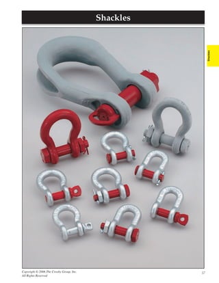
 Shackles s e l k c a h S Shackles Copyright © 2006 The Crosby Group, Inc. 57 All Rights Reserved
  • 2. Shackles_C&E.fm Page 58 Tuesday, January 31, 2006 5:12 PM Shackles What It Takes To Be G-2130 G-209 “Crosby Or Equal” DESIGN COMPETITION CROSBY The theoretical reserve capability of carbon shackles should be as a minimum 5 to 1, and alloy shackles a Ask: What is Working Load Limit and design Crosby carbon shackles have the highest minimum of 5 to 1*. Known as the DESIGN FACTOR, it factor for shackles? design factor (6 to 1) in the industry. is usually computed by dividing the catalog ultimate All of Crosby’s design factors are load by the working load limit. The ultimate load is the Ask: Is deformation upon overloading a criti- documented. Crosby purchases only average load or force at which the product fails or no cal consideration in their design? special bar forging quality steel with longer supports the load. The working load limit is special cleanliness and guaranteed the maximum mass or force which the product is Ask: Do they jeopardize other properties by hardenability. All material chemistry is authorized to support in general service. The design having hardness high in order to increase independently verified prior to factor is generally expressed as a ratio such as 5 to 1. working load or design factor? manufacturing. The design of Crosby Also important to the design of shackles is the selection shackles assure that strength, of proper steel to support fatigue, ductility and impact ductility and fatigue properties. properties are met. CLOSED DIE FORGED Ask: Are their shackles closed die forged with Each shackle is closed die forged. The proper performance of premium shackles depends close tolerance pin holes? Closed die forging produces consistent on good manufacturing techniques that include proper dimensions. Close tolerance holes and forging and accurate machining. Closed die forging of Ask: Do their shackles have good fatigue life? concentric pins with good surface finishes shackles assures clear lettering, superior grain flow, and are provided by Crosby and are proven to consistent dimensional accuracy. A closed die forged Ask: Do their shackles have a fatigue life that provide improved fatigue life in actual bow allows for an increased cross section that, when meets the new world standards? use. Crosby shackles are fatigue rated as coupled with quench and tempering, enhances strength well as load rated. and ductility. Closed die bow forgings combined with Many forge bows, utilizing an open close tolerance pin holes assures good fatigue life. Close die forging process which allows for pin to hole tolerance has been proven to be critical for inconsistent dimensional accuracy and good fatigue life, particularly with screw pin shackles. increased pin hole clearance, thus jeopardizing the fatigue life of the shackle in actual use. QUENCHED AND TEMPERED Ask: Are their bows and pins quenched and All Crosby shackle bows and pins are Quench and tempering assures the uniformity of tempered? quenched and tempered, which enhances performance and maximizes the properties of the steel. their performance under cold tempera- This means that each shackle meets its rated strength Ask: If not, are they willing to accept the tures and adverse field conditions. and has required ductility, toughness, impact and increased risk of inconsistency? Crosby’s Quenched and Tempered carbon fatigue properties. The requirements of your job shackles are recommended for all critical demand this reliability and consistency. This quench Ask: If not, why are they willing to accept applications including overhead lifting. and tempering process develops a tough material that inferior impact, toughness, and product Alloy shackles are recommended when reduces the risk of brittle, catastrophic failure. The deformation? specific dimensional requirements dictate shackle bow will deform if overloading occurs, a size that requires higher working load Ask: Why do many manufacturers not limits. Crosby’s Quenched and Tempered giving warning before ultimate failure. recommend non-heat treated shackles for shackles provide the tensile strength, overhead lifting? ductility, impact and fatigue properties Ask: Why do some recommend Quench and that are essential if they are to perform Tempering for alloy but not carbon grades? time after time in adverse conditions. These properties assure that the inspection Many normalize the shackle bows. As a criteria set forth by ANSI will result, desired properties are not achieved. effectively monitor the ability A few even provide bows in an “as of the shackles to forged” condition, resulting in the continue in service. possibility of brittle failure. IDENTIFICATION AND APPLICATION Ask: Do they have an active traceability Crosby forges “Crosby” or “CG”, the INFORMATION system used in manufacturing? Working Load Limit, and the Product The proper application of shackles requires that the Identification Code (PIC) into each bow correct type and size of shackle be used. The shackle’s Ask: Is the material chemistry independently and pin of its full line of screw pin, round working load limit, its size, a traceability code and the verified? pin, and bolt type anchor and chain manufacturer’s name should be clearly and boldly shackles. marked in the bow. Traceability of the material Ask: What training support is provided? Seminars conducted by Crosby provide chemistry and properties is essential for total training on the proper use of shackles. confidence in the product. Material chemistry Crosby training packets, supplied free to should be independently verified prior to attendees of Crosby seminars, provide manufacturing. training materials needed to explain the proper use of shackles. * G-2160 Wide Body Shackles are metric rated at 5 to 1. G-2140 shackles, 200 ton and above, are rated at 4 to 1 in short tons. Remember, “When buying Crosby, you’re buying more than product, you’re buying Quality.” 58 Copyright © 2006 The Crosby Group, Inc. All Rights Reserved
  • 3. Shackles_C&E.fm Page 59 Tuesday, January 31, 2006 5:13 PM Crosby Value Added • Charpy impact properties: Crosby’s Quenched and Tempered shackles have enhanced impact properties for greater toughness at all temperatures. If requested at the time of order, Crosby can provide Charpy impact properties. • Fatigue properties: Fatigue properties are available for 1/3 to 55 metric ton shackles. These Crosby shackles are fatigue rated to 20,000 cycles at 1-1/2 times the Working Load Limit. • Ductility properties: Typical ductility properties are available for all sizes upon special request. Shackles • Hardness levels and material tensile strengths: Typical values are available for all sizes of shackles, and actual values can Shackles be furnished if requested at the time of order. • Proof Testing: If requested at the time of order, shackles can be furnished proof tested with certificates. • Mag Certification: If requested at the time of order, shackles can be Mag inspected with certificates. • Certification: Certification to World Class Standards is available upon special request at the time of order; American Bureau of Shipping, Lloyds Register of Shipping, Det Norske Veritas, American Petroleum Institute, RINA, Nuclear Regulatory Commission, and several other world wide standards. • Applications: Round Pin Shackles can be used in tie down, towing, suspension or lifting applications where the load is strictly applied in-line. Screw Pin Shackles can be used in any application where a round pin shackle is used. In addition, screw pin shackles can be used for applications involving side-loading circumstances. Reduced working load limits are required for side-loading applications. Bolt-Type Shackles can be used in any application where round pin or screw pin shackles are used. In addition, they are recommended for permanent or long-term installations and where the load may slide on the shackle pin causing the pin to rotate. • Material analysis: Crosby can provide certified material (mill) analysis for each production lot, traceable by the Product Identification Code (PIC). Crosby, through its own laboratory, verifies the analysis of each heat of steel. Crosby purchases only special bar forging quality steel with specific cleanliness requirements and guaranteed hardenability. • Field inspection: Written instructions for visual, magnaflux, and dye penetrant inspection of shackles are available from Crosby. In addition, acceptance criteria and repair procedures for shackles are available. • QUIC-CHECK®: Shackles incorporate two marking indicators forged into the shackle bow at 45° angles from vertical. These are utilized to quickly check the approximate angle of a two-legged hitch or quickly check the angle of a single leg hitch when the shackle pin is secured and the pull of the load is off vertical or side loaded, thus requiring a reduction in the working load limit of the shackle. G-209 S-209 G-213 S-213 G-2130 S-2130 Screw pin anchor Round pin anchor Bolt-type anchor shackles meet the shackles meet the shackles meet the performance performance performance requirements of requirements of requirements of Federal Specification Federal Specification Federal Specification RR-C-271D Type IVA, RR-C-271D Type IVA, RR-C-271D Type IVA, Grade A, Class 2, Grade A, Class 1, Grade A, Grade A, except for those except for those Class 3, except for provisions required of provisions required of those provisions the contractor. the contractor. required of the contractor. G-210 S-210 G-215 S-215 G-2150 S-2150 Screw pin chain Round pin chain Bolt-type chain shackles meet the shackles meet the shackles meet the performance performance performance requirements of requirements of requirements of Federal Specification Federal Specification Federal Specification RR-C-271D Type IVB, RR-C-271D Type IVB, RR-C-271D Type IVB, Grade A, Class 2, Grade A, Class 1, Grade A, Class 3, except for those except for those except for those provisions required of provisions required of provisions required of the contractor. the contractor. the contractor. Copyright © 2006 The Crosby Group, Inc. 59 All Rights Reserved
  • 4. Crosby® Round Pin Shackles ROUND PIN • Capacities 1/2 thru 35 metric tons. ROUND PIN ANCHOR • Forged - Quenched and Tempered, with alloy pins. CHAIN SHACKLES • Working Load Limit permanently shown on every shackle. SHACKLES • Hot Dip galvanized or Self Colored. • Fatigue rated. • Shackles can be furnished proof tested with certificates to designated standards, such as ABS, DNV, Lloyds, or other certification. Charges for proof testing and certification available when requested at the time of order. • Shackles are Quenched and Tempered and can meet DNV impact requirements of 42 joules at -20 degree C. G-213 S-213 • Look for the Red Pin® . . . the mark of genuine Crosby quality. s e l k c a h S n i P d n u o R ® y b s o r C G-215 S-215 Round pin anchor shackles meet the performance requirements of Federal Round pin chain shackles meet the performance requirements of Federal Specification RR-C-271D Type IVA, Grade A, Class 1, except for those provi- Specification RR-C-271D Type IVB, Grade A, Class 1, except for those provi- sions required of the contractor. For additional information, see page 361. sions required of the contractor. For additional information, see page 361. Working Dimensions Tolerance Nominal Load Stock No. SN213Header Weight (mm) +/- Size Limit Each (in.) (t) * G-213 S-213 (kg.) A B C D E F G H N P C A 1/4 1/2 1018017 1018026 .06 11.9 7.85 28.7 6.35 19.8 15.5 32.5 46.7 34.0 6.35 1.50 1.50 5/16 3/4 1018035 1018044 .08 13.5 9.65 31.0 7.85 21.3 19.1 37.3 53.0 40.4 7.85 1.50 1.50 3/8 1 1018053 1018062 .13 16.8 11.2 36.6 9.65 26.2 23.1 45.2 63.0 47.2 9.65 3.30 1.50 7/16 1-1/2 1018071 1018080 .17 19.1 12.7 42.9 11.2 29.5 26.9 51.5 74.0 54.0 11.2 3.30 1.50 1/2 2 1018099 1018106 .32 20.6 16.0 47.8 12.7 33.3 30.2 58.5 83.5 60.5 12.7 3.30 1.50 5/8 3-1/4 1018115 1018124 .68 26.9 19.1 60.5 16.0 42.9 38.1 74.5 106 74.0 17.5 3.30 1.50 3/4 4-3/4 1018133 1018142 1.05 31.8 22.4 71.5 19.1 51.0 46.0 89.0 126 87.0 20.6 6.35 1.50 7/8 6-1/2 1018151 1018160 1.58 36.6 25.4 84.0 22.4 58.0 53.0 102 148 96.5 24.6 6.35 1.50 1 8-1/2 1018179 1018188 2.27 42.9 28.7 95.5 25.4 68.5 60.5 119 167 115 26.9 6.35 1.50 1-1/8 9-1/2 1018197 1018204 3.16 46.0 31.8 108 28.7 74.0 68.5 131 190 130 31.8 6.35 1.50 1-1/4 12 1018213 1018222 4.42 51.5 35.1 119 32.8 82.5 76.0 146 210 140 35.1 6.35 1.50 1-3/8 13-1/2 1018231 1018240 6.01 57.0 38.1 133 36.1 92.0 84.0 162 233 156 38.1 6.35 3.30 1-1/2 17 1018259 1018268 7.82 60.5 41.4 146 39.1 98.5 92.0 175 254 165 41.1 6.35 3.30 1-3/4 25 1018277 1018286 13.4 73.0 51.0 178 46.7 127 106 225 313 197 57.0 6.35 3.30 2 35 1018295 1018302 20.8 82.5 57.0 197 53.0 146 122 253 348 222 61.0 6.35 3.30 G-213 S-213 Working Dimensions Tolerance Nominal Load Stock No. SN215Header Weight (mm) +/- Size Limit Each (in.) (t)* G-215 S-215 (kg) A B C D E F G K N G A 1/4 1/2 1018810 1018829 .05 11.9 7.85 6.35 6.35 24.6 15.5 22.4 40.4 34.0 1.50 1.50 5/16 3/4 1018838 1018847 .08 13.5 9.65 7.85 7.85 29.5 19.1 26.2 48.5 40.4 1.50 1.50 3/8 1 1018856 1018865 .11 16.8 11.2 9.65 9.65 35.8 23.1 31.8 58.5 47.2 3.30 1.50 7/16 1-1/2 1018874 1018883 .18 19.1 12.7 11.2 11.2 41.4 26.9 36.6 67.5 54.0 3.30 1.50 1/2 2 1018892 1018909 .23 20.6 16.0 12.7 12.7 46.0 30.2 41.4 77.0 60.5 3.30 1.50 5/8 3-1/4 1018918 1018927 .55 26.9 19.1 15.7 16.0 58.5 38.1 51.0 95.5 74.0 3.30 1.50 3/4 4-3/4 1018936 1018945 .91 31.8 22.4 20.6 19.1 70.0 46.0 60.5 115 87.0 6.35 1.50 7/8 6-1/2 1018954 1018963 1.49 36.6 25.4 24.6 22.4 81.0 53.0 71.5 135 96.5 6.35 1.50 1 8-1/2 1018972 1018981 2.15 42.9 28.7 25.4 25.4 93.5 60.5 81.0 151 115 6.35 1.50 1-1/8 9-1/2 1018990 1019007 2.86 46.0 31.8 31.8 28.7 103 68.5 91.0 172 130 6.35 1.50 1-1/4 12 1019016 1019025 4.08 51.5 35.1 35.1 31.8 115 76.0 100 191 140 6.35 3.30 1-3/8 13-1/2 1019034 1019043 5.44 57.0 38.1 38.1 35.1 127 84.0 111 210 156 6.35 3.30 1-1/2 17 1019052 1019061 7.33 60.5 41.4 41.1 38.1 137 92.0 122 230 165 6.35 3.30 1-3/4 25 1019070 1019089 13.6 73.0 51.0 54.0 44.5 162 106 146 279 197 6.35 3.30 2 35 1019098 1019105 19.6 82.5 57.0 51.0 53.3 184 122 172 312 222 6.35 3.30 * NOTE: Maximum Proof Load is 2.0 times the Working Load Limit. Minimum Ultimate Strength is 6 times the Working Load Limit. For Working Load Limit reduction due to side loading applications, see page 68. G-215 S-215 60 Copyright © 2006 The Crosby Group, Inc. All Rights Reserved
  • 5. Crosby® Screw Pin Shackles SCREW PIN • Capacities 1/3 thru 55 metric tons. SCREW PIN ANCHOR • Forged - Quenched and Tempered, with alloy pins. CHAIN SHACKLES • Working Load Limit permanently shown on every shackle. SHACKLES Shackles • Hot Dip galvanized or Self Colored. • Fatigue rated. • Shackles can be furnished proof tested with certificates to designated standards, such as ABS, DNV, Lloyds, or other certification. Charges for proof testing and certification available when requested at the time of order. • Shackles are Quenched and Tempered and can meet DNV impact requirements of 42 joules at -20 C. • Sizes 1/2t - 25t meet the performance requirements of EN13889:2003 • Crosby products meet or exceed all requirements of ASME B30.26 G-210 S-210 G-209 S-209 including identification, ductility, design factor, proof load and Screw pin chain shackles meet the Screw pin anchor shackles meet the temperature requirements. Importantly, Crosby products meet other performance requirements of Federal performance requirements of Federal critical performance requirements including fatigue life, impact Specification RR-C-271D, Type IVB, Specification RR-C-271D Type IVA, Grade A, Class 2, except for those provi- properties and material traceability, not addressed by ASME B30.26. Grade A, Class 2, except for those provi- sions required of the contractor. For sions required of the contractor. For • Look for the Red Pin® . . . the mark of genuine Crosby quality. additional information, see page 361. additional information, see page 361. s e l k c a h S n i P w e r c S ® y b s o r C Working Dimensions Tolerance Nominal Load Stock No. SN209Header Weight (mm) +/- Size Limit Each (in.) (t) * G-209 S-209 (kg) A B C D E F G H L M P C A 3/16 1/3 1018357 - .03 9.65 6.35 22.4 4.85 15.2 14.2 24.9 37.3 4.06 28.4 4.85 1.50 1.50 1/4 1/2 1018375 1018384 .05 11.9 7.85 28.7 6.35 19.8 15.5 32.5 46.7 4.85 35.1 6.35 1.50 1.50 5/16 3/4 1018393 1018400 .09 13.5 9.65 31.0 7.85 21.3 19.1 37.3 53.0 5.60 42.2 7.85 3.30 1.50 3/8 1 1018419 1018428 .14 16.8 11.2 36.6 9.65 26.2 23.1 45.2 63.0 6.35 51.5 9.65 3.30 1.50 7/16 1-1/2 1018437 1018446 .17 19.1 12.7 42.9 11.2 29.5 26.9 51.5 74.0 7.85 60.5 11.2 3.30 1.50 1/2 2 1018455 1018464 .33 20.6 16.0 47.8 12.7 33.3 30.2 58.5 83.5 9.65 68.5 12.7 3.30 1.50 5/8 3-1/4 1018473 1018482 .62 26.9 19.1 60.5 16.0 42.9 38.1 74.5 106 11.2 85.0 17.5 6.35 1.50 3/4 4-3/4 1018491 1018507 1.07 31.8 22.4 71.5 19.1 51.0 46.0 89.0 126 12.7 101 20.6 6.35 1.50 7/8 6-1/2 1018516 1018525 1.64 36.6 25.4 84.0 22.4 58.0 53.0 102 148 12.7 114 24.6 6.35 1.50 1 8-1/2 1018534 1018543 2.28 42.9 28.7 95.5 25.4 68.5 60.5 119 167 14.2 129 26.9 6.35 1.50 1-1/8 9-1/2 1018552 1018561 3.36 46.0 31.8 108 29.5 74.0 68.5 131 190 16.0 142 31.8 6.35 1.50 1-1/4 12 1018570 1018589 4.31 51.5 35.1 119 32.8 82.5 76.0 146 210 17.5 156 35.1 6.35 1.50 1-3/8 13-1/2 1018598 1018605 6.14 57.0 38.1 133 36.1 92.0 84.0 162 233 19.1 174 38.1 6.35 3.30 1-1/2 17 1018614 1018623 7.80 60.5 41.4 146 39.1 98.5 92.0 175 254 20.6 187 41.1 6.35 3.30 1-3/4 25 1018632 1018641 12.6 73.0 51.0 178 46.7 127 106 225 313 25.4 231 57.0 6.35 3.30 2 35 1018650 1018669 20.4 82.5 57.0 197 53.0 146 122 253 348 31.0 263 61.0 6.35 3.30 2-1/2 55 1018678 1018687 38.9 105 70.0 267 69.0 184 145 327 453 35.1 330 79.5 6.35 6.35 G-209 S-209 Working Dimensions Tolerance Nominal Load Stock No. SN210Header Weight (mm) +/- Size Limit Each (in.) (t)* G-210 S-210 (kg) A B C D E F G K L M G A 1/4 1/2 1019150 1019169 .05 11.9 7.85 6.35 6.35 24.6 15.5 22.4 40.4 4.85 35.1 1.50 1.50 5/16 3/4 1019178 1019187 .08 13.5 9.65 7.85 7.85 29.5 19.1 26.2 48.5 5.60 42.2 1.50 1.50 3/8 1 1019196 1019203 .13 16.8 11.2 9.65 9.65 35.8 23.1 31.8 58.5 6.35 51.5 3.30 1.50 7/16 1-1/2 1019212 1019221 .20 19.1 12.7 11.2 11.2 41.4 26.9 36.6 67.5 7.85 60.5 3.30 1.50 1/2 2 1019230 1019249 .27 20.6 16.0 12.7 12.7 46.0 30.2 41.4 77.0 9.65 68.5 3.30 1.50 5/8 3-1/4 1019258 1019267 .57 26.9 19.1 15.7 16.0 58.5 38.1 51.0 95.5 11.2 85.0 3.30 1.50 3/4 4-3/4 1019276 1019285 1.20 31.8 22.4 20.6 19.1 70.0 46.0 60.5 115 12.7 101 6.35 1.50 7/8 6-1/2 1019294 1019301 1.43 36.6 25.4 24.6 22.4 81.0 53.0 71.5 135 12.7 114 6.35 1.50 1 8-1/2 1019310 1019329 2.15 42.9 28.7 25.4 25.4 93.5 60.5 81.0 151 14.2 129 6.35 1.50 1-1/8 9-1/2 1019338 1019347 3.06 46.0 31.8 31.8 28.7 103 68.5 91.0 172 16.0 142 6.35 1.50 1-1/4 12 1019356 1019365 4.11 51.5 35.1 35.1 31.8 115 76.0 100 191 17.5 156 6.35 3.30 1-3/8 13-1/2 1019374 1019383 5.28 57.0 38.1 38.1 35.1 127 84.0 111 210 19.1 174 6.35 3.30 1-1/2 17 1019392 1019409 7.23 60.5 41.4 41.1 38.1 137 92.0 122 230 20.6 187 6.35 3.30 1-3/4 25 1019418 1019427 12.1 73.0 51.0 54.0 44.5 162 106 146 279 25.4 231 6.35 3.30 2 35 1019436 1019445 19.2 82.5 57.0 60.0 51.0 184 122 172 312 31.0 263 6.35 3.30 2-1/2 55 1019454 1019463 32.5 105 70.0 66.5 66.5 238 145 203 377 35.1 330 6.35 6.35 * NOTE: Maximum Proof Load is 2.0 times the Working Load Limit. Minimum Ultimate Strength is 6 times the Working Load Limit. For Working Load Limit reduction due to side loading applications, see page 68. G-210 S-210 Copyright © 2006 The Crosby Group, Inc. 61 All Rights Reserved
  • 6. Crosby® Alloy Screw Pin Shackles G-209A • Capacities 2 thru 21 metric tons. • Forged Alloy Steel - Quenched and Tempered, with alloy pins. • Working Load Limit permanently shown on every shackle. • Hot Dip Galvanized. • Crosby products meet or exceed all requirements of ASME B30.26 including identification, ductility, design factor, proof load and temperature requirements. Importantly, Crosby products meet other critical performance requirements including fatigue life, impact properties and material traceability, not addressed by ASME B30.26. • Shackles can be furnished proof tested with certificates to designated standards, such as ABS, DNV, Lloyds, or other Screw pin anchor shackles meet the certification. Charges for proof testing and certification available performance requirements of Federal when requested at the time of order. Specification RR-C-271D Type IVA, s e l k c a h S n i P w e r c S y o l l A ® y b s o r C Grade B, Class 2, except for those provi- sions required of the contractor. For additional information, see page 361. G-209A Crosby® Alloy Screw Pin Shackles Nominal Working SN209AHeader Weight Dimensions Tolerance Size Load Limit G-209-A Each (mm) +/- (in.) (t)* Stock No. (kg) A B C D E F G H L M P C A 3/8 2 1017450 .14 16.8 11.2 36.6 9.65 26.2 23.1 45.2 63.5 6.35 51.5 9.65 3.30 1.50 7/16 2-2/3 1017472 .17 19.1 12.7 42.9 11.2 29.5 26.9 51.5 74.0 7.85 60.5 11.2 3.30 1.50 1/2 3-1/3 1017494 .29 20.6 16.0 47.8 12.7 23.3 30.2 58.5 83.5 9.65 68.5 12.7 3.30 1.50 5/8 5 1017516 .63 26.9 19.1 60.5 16.0 42.9 38.1 74.5 106 11.2 85.0 17.5 3.30 1.50 3/4 7 1017538 1.02 31.8 22.4 71.5 19.1 51.0 46.0 89.0 126 12.7 101 20.6 6.35 1.50 7/8 9-1/2 1017560 1.53 36.6 25.4 84.0 22.4 58.0 53.0 102 148 12.7 114 24.6 6.35 1.50 1 12-1/2 1017582 2.41 42.9 28.7 95.5 25.4 68.5 60.5 119 167 14.2 129 26.9 6.35 1.50 1-1/8 15 1017604 3.09 46.0 31.8 108 29.5 74.0 68.5 131 190 16.0 142 31.8 6.35 1.50 1-1/4 18 1017626 4.31 51.5 35.1 119 32.8 82.5 76.0 146 210 17.5 156 35.1 6.35 1.50 1-3/8 21 1017648 6.01 57.0 38.1 133 36.1 92.0 84.0 162 233 19.1 174 38.1 6.35 3.30 * Maximum Proof Load is 2 times the Working Load Limit (metric tons). Minimum Ultimate Load is 4.5 times Working Load Limit based on Metric tons. For Working Load Limit reduction due to side loading applications, see page 68. 62 Copyright © 2006 The Crosby Group, Inc. All Rights Reserved
  • 7. Crosby® Bolt Type Shackles BOLT TYPE • Working Load Limit permanently shown on every shackle. BOLT TYPE Capacities 1/3 thru 150 metrics tons. ANCHOR CHAIN • Forged — Quenched and Tempered, with alloy pins. SHACKLES SHACKLES Shackles • Hot Dip galvanized or Self Colored. • Fatigue rated. • Crosby products meet or exceed all requirements of ASME B30.26 including identification, ductility, design factor, proof load and temperature requirements. Importantly, Crosby products meet other critical performance requirements including fatigue life, impact properties and material traceability, not addressed by ASME B30.26. • Sizes 1/2t - 25t meet the performance requirements of EN13889:2003 • Shackles 55 metric tons and smaller can be furnished proof tested with G-2130 S-2130 certificates to designated standards, such as ABS, DNV, Lloyds, or G-2150 S-2150 Bolt Type Anchor shackles with thin other certification when requested at time of order. Bolt Type Chain shackles. Thin hex head head bolt - nut with cotter pin. Meets the bolt - nut with cotter pin. Meets the performance requirements of Federal • Shackles 85 metric tons and larger can be provided as follows. performance requirements of Federal Specification RR-C-271D Type IVA, Specification RR-C271D Type IVB, Grade • Non Destructive Tested Grade A, Class 3, except for those provi- A, Class 3, except for those provisions • Serialized Pin and Bow sions required of the contractor. For required of the contractors. For • Material Certification (Chemical) Certification must be additional information, see page 361. additional information, see page 361. requested at time of order. • Look for the Red Pin® . . . the mark of genuine Crosby quality. s e l k c a h S e p y T t l o B ® y b s o r C Nominal Working Weight Dimensions Tolerance Size Load Limit Stock No. SN2130Header Each (mm) +/- (in.) (t) * G-2130 S-2130 (kg) A B C D E F H L N C A 3/16 1/3‡ 1019464 - .03 9.65 6.35 22.4 4.85 15.2 14.2 37.3 24.9 4.85 1.50 1.50 1/4 1/2 1019466 - .05 11.9 7.85 28.7 6.35 19.8 15.5 46.7 32.5 6.35 1.50 1.50 5/16 3/4 1019468 - .10 13.5 9.65 31.0 7.85 21.3 19.1 53.0 37.3 7.85 3.30 1.50 3/8 1 1019470 - .15 16.8 11.2 36.6 9.65 26.2 23.1 63.0 45.2 9.65 3.30 1.50 7/16 1-1/2 1019471 - .22 19.1 12.7 42.9 11.2 29.5 26.9 74.0 51.5 11.2 3.30 1.50 1/2 2 1019472 1019481 .36 20.6 16.0 47.8 12.7 33.3 30.2 83.5 58.5 12.7 3.30 1.50 5/8 3-1/4 1019490 1019506 .62 26.9 19.1 60.5 16.0 42.9 38.1 106 74.5 17.5 6.35 1.50 3/4 4-3/4 1019515 1019524 1.23 31.8 22.4 71.5 19.1 51.0 46.0 126 89.0 20.6 6.35 1.50 7/8 6-1/2 1019533 1019542 1.79 36.6 25.4 84.0 22.4 58.0 53.0 148 102 24.6 6.35 1.50 1 8-1/2 1019551 1019560 2.28 42.9 28.7 95.5 25.4 68.5 60.5 167 119 26.9 6.35 1.50 1-1/8 9-1/2 1019579 1019588 3.75 46.0 31.8 108 28.7 74.0 68.5 190 131 31.8 6.35 1.50 1-1/4 12 1019597 1019604 5.31 51.5 35.1 119 31.8 82.5 76.0 210 146 35.1 6.35 1.50 1-3/8 13-1/2 1019613 1019622 7.18 57.0 38.1 133 35.1 92.0 84.0 233 162 38.1 6.35 3.30 1-1/2 17 1019631 1019640 9.43 60.5 41.4 146 38.1 98.5 92.0 254 175 41.1 6.35 3.30 1-3/4 25 1019659 1019668 15.4 73.0 51.0 178 44.5 127 106 313 225 57.0 6.35 3.30 2 35 1019677 1019686 23.7 82.5 57.0 197 51.0 146 122 348 253 61.0 6.35 3.30 2-1/2 55 1019695 1019702 44.6 105 70.0 267 66.5 184 145 453 327 79.5 6.35 6.35 3 † 85 1019711 - 70 127 82.5 330 76.0 200 165 546 365 92.0 6.35 6.35 G-2130 S-2130 3-1/2 † 120 ‡ 1019739 - 120 133 95.5 372 92.0 229 203 626 419 105 6.35 6.35 4 † 150 ‡ 1019757 - 153 140 108 368 104 254 229 653 468 116 6.35 6.35 Nominal Working Weight Dimensions Tolerance Size Load Limit Stock No. SN2150Header Each (mm) +/- (in.) (t)* G-2150 S-2150 (kg) A B D F G K M P R G A 1/4 1/2 1019768 - .06 11.9 7.85 6.35 15.5 19.1 40.4 24.6 39.6 6.35 1.50 1.50 5/16 3/4 1019770 - .10 13.5 9.65 7.85 19.1 25.4 48.5 29.5 46.2 7.85 1.50 1.50 3/8 1 1019772 - .15 16.8 11.2 9.65 23.1 31.0 58.5 35.8 55.0 9.65 3.30 1.50 7/16 1-1/2 1019774 - .22 19.1 12.7 11.2 26.9 36.1 67.5 41.1 63.5 11.2 3.30 1.50 1/2 2 1019775 1019784 .34 20.6 16.0 12.7 30.2 41.4 77.0 46.0 71.0 12.7 3.30 1.50 5/8 3-1/4 1019793 1019800 .67 26.9 19.1 16.0 38.1 51.0 95.5 58.5 89.5 16.0 3.30 1.50 3/4 4-3/4 1019819 1019828 1.14 31.8 22.4 19.1 46.0 60.5 115 70.0 103 20.6 6.35 1.50 7/8 6-1/2 1019837 1019846 1.74 36.6 25.4 22.4 53.0 71.5 135 81.0 120 24.6 6.35 1.50 1 8-1/2 1019855 1019864 2.52 42.9 28.7 25.4 60.5 81.0 151 93.5 135 25.4 6.35 1.50 1-1/8 9-1/2 1019873 1019882 3.45 46.0 31.8 28.7 68.5 91.0 172 103 150 31.8 6.35 1.50 1-1/4 12 1019891 1019908 4.90 51.5 35.1 31.8 76.0 100 191 115 165 35.1 6.35 1.50 1-3/8 13-1/2 1019917 1019926 6.24 57.0 38.1 35.1 84.0 111 210 127 183 38.1 6.35 3.30 1-1/2 17 1019935 1019944 8.39 60.5 41.4 38.1 92.0 122 230 137 196 41.1 6.35 3.30 1-3/4 25 1019953 1019962 14.2 73.0 51.0 44.5 106 146 279 162 230 54.0 6.35 3.30 2 35 1019971 1019980 21.2 82.5 57.0 51.0 122 172 312 184 264 60.0 6.35 3.30 2-1/2 55 1019999 1020004 38.6 105 70.0 66.5 145 203 377 238 344 66.5 6.35 6.35 3 † 85 1020013 - 56 127 82.5 76.0 165 216 429 279 419 89.0 6.35 6.35 * NOTE: Maximum Proof Load is 2.0 times the Working Load Limit. Minimum Ultimate Strength is 6 times the Working Load Limit. For Working Load Limit reduction due to side loading applications, see page 68. † Individually Proof Tested with G-2150 S-2150 certification. ‡ Furnished in Anchor style only and furnished with Round Head Bolts with welded handles. Copyright © 2006 The Crosby Group, Inc. 63 All Rights Reserved
  • 8. Crosby® Alloy Bolt Type Shackles G-2140 / S-2140 • Quenched and Tempered. ALLOY • Alloy bows, Alloy bolts. BOLT TYPE • Forged Alloy Steel 30 thru 175 metric tons. Cast Alloy Steel 200 thru 400 metric tons. ANCHOR SHACKLES • Working Load Limit is permanently shown on every shackle. • All sizes are individually proof tested to 2.0 times the Working Load Limit. • Pins are galvanized and painted red. • Shackles are Quenched and Tempered and can meet DNV impact requirements of 42 joules at -20 C. • Crosby products meet or exceed all requirements of ASME B30.26 including identification, ductility, design factor, proof load and temperature requirements. Importantly, Crosby products meet other critical performance requirements including fatigue life, impact properties and material traceability, not G-2140 meets the performance require- addressed by ASME B30.26. ments of Federal Specification RR-C- • Shackles 200 metric tons and larger are provided as follows. 271D, Type IVA, Grade B, Class 3, except for those provisions required of the • Non Destructive Tested contractor. For additional information, • Serialized Pin and Bow see page 361. • Material Certification (Chemical) • Magnetic Particle Inspected. • Certification must be requested at time of order. s e l k c a h S e p y T t l o B y o l l A ® y b s o r C Nominal Working Dimensions Tolerance Shackle Load Stock No. SN2140Header Weight (mm) +/- Size Limit Each (in.) (t)* G-2140 S-2140 (kg) A B C D E F G H J K L A E 1-1/2 30 1021110 1021129 8.52 60.5 92.0 41.1 41.4 146 35.3 175 197 254 98.5 39.1 3.30 6.35 1-3/4 40 1021138 1021147 15.4 73.0 106 57.0 51.0 178 44.5 225 230 313 127 46.7 3.30 6.35 2 55 1021156 1021165 23.6 82.5 122 61.0 57.0 197 51.0 253 264 348 146 53.0 3.30 6.35 2-1/2 85 1021174 1021183 43.5 105 145 79.0 71.0 267 66.5 327 344 453 184 69.0 6.35 6.35 3 120 1021192 - 81 127 165 92.0 82.5 330 76.0 365 419 546 200 79.0 6.35 6.35 3-1/2 † 150 1021218 - 120 133 203 105 95.5 372 95.5 419 483 625 229 92.0 6.35 6.35 4 † 175 1021236 - 153 140 229 116 108 368 102 468 502 626 254 104 6.35 6.35 4-3/4** † 200 1021414 - 204 184 267 152 121 397 95.5 533 521 743 279 114 6.35 6.35 5 ** † 250 1021432 - 272 216 305 165 127 508 98.5 622 558 889 330 114 6.35 6.35 6 ** † 300 1021450 - 352 213 305 172 152 495 121 635 618 895 330 127 6.35 6.35 7 ** † 400 1021478 - 500 210 356 184 178 572 165 660 710 1022 330 152 6.35 6.35 * Note: Maximum Proof Load is 2.0 times the Working Load Limit. Minimum Ultimate Load is 4 times the Working Load Limit on 200 thru 400 metric Tons. For sizes 30 thru 175 metric Tons, Minimum Ultimate Load is 5.4 times the Working Load Limit. ** Cast Alloy Steel. † Furnished with Round Head Bolts with welded handle. For Working Load Limit reduction due to side loading applications, see page 68. 64 Copyright © 2006 The Crosby Group, Inc. All Rights Reserved
  • 9. Crosby® Wide Body Shackles G-2160 • All sizes Quenched and Tempered for maximum strength. "WIDE BODY" • Forged alloy steel from 30 through 300 metric tons. SHACKLES • Cast alloy steel from 400 through 1000 metric tons. Shackles • Sizes 300 tons and smaller are proof tested to 2 times the Working Load Limit. • Sizes 400 tons and larger are tested to 1.33 times Working Load Limit. • All ratings are in metric tons, embossed on side of bow. • Bows and pins are furnished Dimetcoted. All Pins are Dimetcoted then painted red. • Greatly improves wearability of wire rope slings. • Can be used to connect HIGH STRENGTH Synthetic Web Slings, HIGH STRENGTH Synthetic Round Slings or Wire Rope Slings. • Increase in shackle bow radius provides minimum 58% gain in sling bearing surface and eliminates need for a thimble. • Increases usable sling strength minimum of 15%. • Pin is non-rotating, with weld on handles for easier use (300t and larger). Patented • All 2160 shackles are individually proof tested and magnetic particle inspected. Crosby certification available at time of order. • Crosby products meet or exceed all requirements of ASME B30.26 including identification, ductility, design factor, proof load and temperature requirements. Importantly, Crosby products meet other critical performance requirements including fatigue life, impact properties and material traceability, not addressed by ASME B30.26. • Shackles requiring ABS, DNV, Lloyds and other certifications are available upon special request and must be specified at time of order. • Shackles are produced in accordance with certified lifting appliance requirements. • Non Destructive Testing • Serialization / Identification • Material Testing (Physical / Chemical / Charpy) • Proof Testing s e l k c a h S y d o B e d i W ® y b s o r C Dimensions (mm) Working G-2160 Weight B D Load Limit Stock Each +/- +/- (t)* No. G-2160 (kg) A 6.35 C .5 E G H J K P R † 30 1021575 11.3 197 60.5 35.1 41.4 90.4 51.0 165 79.5 63.5 232 279 † 40 1021584 15.9 230 73.2 44.5 51.0 102 58.7 205 95.3 76.2 270 346 † 55 1021593 32.2 264 82.5 51.0 57.4 118 66.8 238 114 88.9 327 394 † 75 1021290 45 346 105 54.0 70.0 121 64.0 290 120 92.5 313 465 † 125 1021307 73 400 130 65.0 80.0 145 80.0 365 150 110 380 576 † 200 1021316 227 508 150 85.0 105 185 110 480 205 137 495 757 † 300 1021325 368 591 185 102 133 235 140 600 265 160 601 950 †† 400 1021334 472 715 220 131 160 280 160 575 320 185 690 985 †† 500 1021343 625 809 250 142 180 318 170 630 340 225 790 1085 †† 600 1021352 831 913 275 153 200 350 185 700 370 247 865 1200 †† 700 1021361 1109 992 300 167 215 376 200 735 400 270 940 1275 †† 800 1021254 1368 986 325 183 230 400 210 750 420 277 975 1323 †† 900 1021389 1559 1050 350 198 250 430 220 757 440 293 1025 1373 ††1000 1021370 1824 1176 380 212 270 450 230 760 460 308 1075 1405 * Ultimate Load is 5 times the Working Load Limit. † Forged Alloy Steel. Proof Load is 2 times the Working Load Limit. †† Cast Alloy Steel. Proof Load is 1.33 times the Working Load Limit. Copyright © 2006 The Crosby Group, Inc. 65 All Rights Reserved
  • 10. Crosby® COLD TUFF® Shackles G-2130CT • Forged - Quenched and Tempered, with alloy bolt. & • G-2130CT - Carbon Steel • G-2140CT - Alloy Steel G-2140CT • Working Load Limit permanently shown on every shackle. • Individually Serialized with Certification. • Fatigue Rated (G-2130CT only). • All sizes are individually proof tested to 2.0 times the Working Load Limit. • Finish is Inorganic Zinc Primer or Hot Dipped Galvanized. • Bow and Bolt are Certified to meet charpy impact testing of 31 ft-lbs. min. ave. at -4° F. • Individually Mag Inspected with certification. • Type Approval and certification in accordance with DNV Specification 2.7-1 Offshore Containers and DNV rules for Lifting Appliances - Loose Gear. • COLD TUFF® shackles are suitable for use to -50° F. s e l k c a h S ® F F U T D L O C ® y b s o r C G-2130CT • Bolt Type Anchor shackle with thin head bolt - nut with cotter pin. Meets the performance requirements of Federal Specification RR-C271D Type IVA, Grade A, Class 3, except for those provisions required of the contractor. For additional information, see page 361. Nominal Working SN2130CTHeader Dimensions Tolerance Shackle Load G-2130 CT Weight (mm) +/- Size Limit Stock Each (in.) (t)* No. (kg) A B C D E F H L N P A C 3/4 4-3/4 1260568 1.23 31.8 22.4 71.5 19.1 51.0 46.0 126 89.0 20.6 108 1.50 6.35 7/8 6-1/2 1260577 1.76 36.6 25.4 84.0 22.4 58.0 53.0 148 102 24.6 120 1.50 6.35 1 8-1/2 1260586 2.57 42.9 28.7 95.5 26.2 68.5 60.5 167 119 26.9 137 1.50 6.35 1-1/8 9-1/2 1260595 3.75 46.0 31.8 108 28.7 74.0 68.5 190 131 31.8 150 1.50 6.35 1-1/4 12 1260604 5.31 51.5 35.1 119 32.8 82.5 76.0 210 146 35.1 168 1.50 6.35 1-3/8 13-1/2 1260613 6.85 57.0 38.1 133 35.1 92.0 84.0 233 162 38.1 183 3.30 6.35 1-1/2 17 1260622 9.43 60.5 41.4 146 39.1 98.5 92.0 254 175 41.1 195 3.30 6.35 1-3/4 25 1260633 15.4 73.0 51.0 178 46.7 127 106 313 225 57.0 233 3.30 6.35 * NOTE:For Working Load Limit reduction due to side loading applications, see page 68. G-2140CT • G-2140 meets the performance requirements of Federal Specifications RR-C-271D, Type IVA, Grade B, Class 3 except for those provisions required of the contractor. For additional information, see page 361. Nominal Working SN2140CTHeader Dimensions Tolerance Shackle Load G-2140 CT Weight (mm) +/- Size Limit Stock Each (in.) (t)* No. (kg) A B C D E F H L N P A C 1-1/2 30 1260801 9.43 60.5 41.4 146 39.1 98.5 92.0 254 175 41.1 195 3.30 6.35 1-3/4 40 1260812 15.4 73.0 51.0 178 46.7 127 106 313 225 57.0 233 3.30 6.35 2 55 1260823 23.6 82.5 57.0 197 53.0 146 122 348 253 61.0 258 3.30 6.35 2-1/2 85 1260834 43.5 105 70.0 267 69.0 184 145 453 327 79.0 329 6.35 6.35 3 120 1260843 81 127 82.5 330 79.0 200 165 546 365 92.0 419 6.35 6.35 3-1/2 † 150 1260852 120 133 95.5 372 92.0 229 203 625 419 105 483 6.35 6.35 4 † 175 1260861 153 140 108 368 104 254 229 626 468 116 502 6.35 6.35 4 3/4 † 200 1260870 204 184 121 397 114 279 267 743 533 152 521 6.35 6.35 5 † 250 1260889 272 216 127 508 114 330 305 889 622 165 558 6.35 6.35 * NOTE: Maximum Proof Load is 2.0 times the Working Load Limit. 4-3/4t - 175 t, Minimum Ultimate Load is 5.4 times the Working Load Limit. 200t and larger, Minimum Ultimate Load is 4 times the Working Load Limit. † Furnished with Round Head Bolts with welded handle. 66 Copyright © 2006 The Crosby Group, Inc. All Rights Reserved
  • 11. Shackle_67.fm Page 25 Tuesday, January 31, 2006 5:24 PM Crosby® Shackles APPLICATION INFORMATION Shackles Round Pin Shackles can be used in tie down, towing, suspension or lifting applications where the load is strictly applied in-line. G/S-213 G/S-215 G-209 A G/S-209 G/S-210 Screw Pin Shackles can be used in any application where a round pin shackle is used. In addition, screw pin shackles can be used for applications involving side-loading circumstances. Reduced working load limits are required for side-loading applications. While in service, do not allow the screw pin to be rotated by a live line, such as a choker application. G/S-2130 G/S-2150 G/S-2140 G-2160 Bolt-Type Shackles can be used in any applications where round pin or screw pin shackles are used. In addition, they are recommended for permanent or long term installations and where the load may slide on the shackle pin causing the pin to rotate. QUIC-CHECK® INFORMATION All Crosby Shackles, except for G-2160’s incorporate markings forged into the product which address an easy QUIC-CHECK® feature. Angle indicators are forged into the shackle bow at 45° angles from vertical. These are utilized to quickly check the approximate angle of a two-legged hitch or quickly check the angle of a single leg hitch when the shackle pin is secured and the pull of the load is off vertical or side loaded, thus requiring a reduction in the working load limit of the shackle. G-2130 Copyright © 2006 The Crosby Group, Inc. 67 All Rights Reserved
  • 12. Shackle_67.fm Page 26 Tuesday, January 31, 2006 5:27 PM Crosby® Shackles Angle loads must be applied in the plane of Side Loading Reduction Chart the bow. IN-LINE For Screw Pin and Bolt Type Shackles Only + Angle of Side Load from Vertical In-Line of Shackle Adjusted Working Load Limit 0° In-Line* 100% of Rated Working Load Limit 45 45° from In-Line* 70% of Rated Working Load Limit DEGREES 90° from In-Line* 50% of Rated Working Load Limit * In-Line load is applied perpendicular to pin. + DO NOT SIDE LOAD ROUND PIN SHACKLE 90 DEGREES Shackles symmetrically loaded with Never Exceed 120° included angle. two leg slings having a maximum Use Bolt Type and Screw Pin Shackles ONLY. included angle of 120° can be utilized to full Working Load Limit. L L 68 Copyright © 2006 The Crosby Group, Inc. All Rights Reserved