
Recomendados
Recomendados
Más contenido relacionado
La actualidad más candente
La actualidad más candente (20)
Similar a Research Inventy : International Journal of Engineering and Science is published by the group of young academic and industrial researchers with 12 Issues per year.
Similar a Research Inventy : International Journal of Engineering and Science is published by the group of young academic and industrial researchers with 12 Issues per year. (20)
Research Inventy : International Journal of Engineering and Science is published by the group of young academic and industrial researchers with 12 Issues per year.
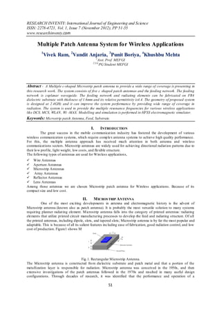
- 1. RESEARCH INVENTY: International Journal of Engineering and Science ISSN: 2278-4721, Vol. 1, Issue 7 (November 2012), PP 51-55 www.researchinventy.com Multiple Patch Antenna System for Wireless Applications 1 Vivek Ram, 2Vandit Anjaria, 3Punit Boriya, 4Khushbu Mehta 1 Asst. Prof. MEFGI 2,3,4, PG Student MEFGI Abstract - A Multiple c-shaped Microstrip patch antenna to provide a wide range of coverage is presenting in this research work. The system consists of five c shaped patch antennas and the feeding network. The feeding network is coplanar waveguide. The feeding network and radiating elements can be fabricated on FR4 dielectric substrate with thickness of 1.6mm and its relative permittivity is4.4. The geometry of proposed system is designed at 2.4GHz and it can improve the system performance by providing wide range of coverage in radiation. The system is used to provide the multiple resonance frequencies for various wireless applications like DCS, MCS, WLAN , Wi -MAX. Modelling and simulation is performed in HFSS electromagnetic simulator. Keywords: Microstrip patch Antenna, Feed, Substrate. I. INTRODUCTION The great success in the mobile co mmunicat ion industry has fostered the development of various wireless communication systems, which require comp lex antenna systems to achieve high quality performance. For this, the mu ltiple antenna approach has received much attention in both antenna and wireless communicat ions sectors. Microstrip antennas are widely used for achieving directional radiat ion patterns due to their lo w profile, light weight, low costs, and flexible structure. The following types of antennas are used for Wireless application s, Wire Antennas Aperture Antennas Microstrip Antennas Array Antennas Reflector Antennas Lens Antennas Among those antennas we are chosen Microstrip patch antenna for Wireless applications. Because of its compact size and low cost. II. M ICROS TRIP ANTENNA One of the most exciting developments in antenna and electromagnetic history is the advent of Microstrip antenna (known also as patch antenna). It is probably the most versatile solution to many systems requiring planner radiat ing element. M icrostrip antenna falls into the category of printed antennas: radiating elements that utilize printed circuit manufacturing processes to develop the feed and radiating structure. Of all the printed antennas, including dipole, slots, and tapered slots; Microstrip antenna is by far the most popular and adaptable. This is because of all its salient features including ease of fabrication, good radiation control, and low cost of production. Figure1 shows M Fig.1. Rectangular M icrostrip Antenna. The Microstrip antenna is constructed fro m dielectric substrate and patch metal and that a portion of the metallization layer is responsible for radiation. Microstrip antenna was conceived in the 1950s, and then extensive investigations of the patch antennas followed in the 1970s and resulted in many useful design configurations. Through decades of research, it was identified that the performance and operation of a 51
- 2. Multiple Patch Antenna System for Wireless Applications Microstrip antenna is driven mainly by the geometry of the printed patch and the material characteristics of the substrate onto which the antenna is printed. There are several techniques available to feed or transmit electro magnetic energy to a Microstrip antenna. The four most popular feeding methods are the 1. Coaxial probe 2. M icrostrip line (edge feed and inset feed) 3. Aperture coupling 4. Pro ximity coupling 5. Coplanar waveguide feed III. M ULTIPLE C-PATCH ANTENNA We are going to implement multip le C-shaped patch antenna for the Wireless applications and also overcomes the bandwidth capability of the existing sys tem. our system has mult iple frequency bands. Fig.2. shows existing C-shaped patch antenna Fig.2. Exist ing C shaped patch antenna To increase the bandwidth capability of the patch antennas the following Techniques are used, a) By adjusting the length &width of antenna b) By ad justing gap between different patches c) By having proper dielectric substrates d) By having different feeding techniques VI. DESIGN OF MULTIPLE C-SHAPED ANTENNAS 1.1 Design Parameter 1.1.1 Width of the Microstrip line (w): The transmission line characteristics impedance Z0 and relative dielectric constant εr, then t he W/h ratio can be found as, W 8e4 W 2A for 2 h e 2 h Where Z 0 ( r 1) r 1 0.11 A 0.23 60 2 r 1 r 1.1.2.EFFECT IVE DIELECT RIC CONST ANT (𝜀_𝑟𝑒𝑓𝑓) 1 _ r 1 _ r 1 h 2 _ reff 1 12 W 2 2 εr - The d ielectric constant of the substrate εreff - Effective d ielectric constant h -Height of the dielectric substrate w -W idth of the patch 52
- 3. Multiple Patch Antenna System for Wireless Applications 1.1.3. Guided wavelength (λg): The guided wavelength is given by 0 g reff where εreff is effective d ielectric constant of the microstrip line and λ 0 is free space wavelength in m, wh ich is given by, c 0 fr Where c is velocity of light in m/s, fr is resonant frequency in Hz.. I. SIMULATION RES ULTS Fig.3. Proposed C-shaped Model in HFSS Fig.4. 3-D view of the mu ltiple c-shaped patch antennas Fig.5.Frequency Response of the multip le c shaped antenna 53
- 4. Multiple Patch Antenna System for Wireless Applications Fig.6.Radiat ion Pattern of Proposed C-shaped antenna Fig.7. Rad iation pattern REx at 20 db normalized Fig.8. Rad iation pattern REy at 20 db normalized V . M ATLAB CODE FOR CALC ULATION er=4.4; fr=2.4*10^9; h=1.6; z=input('Impedance:'); a=sqrt((er+1)/ 2); b=(er-1)/(er+1); c=(.23+(.11/er)); A=((z/60)*a)+(b*c); w=(8*exp (A)/(exp (2*A)-2))*h; disp('Width of the patch'); disp(w); a1=(er+1)/2; b1=(er-1)/ 2; c1=power((1+(12*(h/w))),-.5); eeff=a1+(b1*c1); disp('Effective d ilectric constant of patch'); disp(eeff); lamda0=(3*10^8*1000)/fr; disp('lamda zero'); disp(lamda0); lamdag=lamda0/sqrt(eeff); disp('lamda g'); disp(lamdag); 54
- 5. Multiple Patch Antenna System for Wireless Applications VII CONCLUS ION Multiple c -shaped patch antenna is simulated and fabricated on FR-4 dielectric substrate where the simu lated return loss is 20 dB at 6.7 Gh z, 10db at 4.4 GHz and 14db at 1.8 GHz. Thus we are getting triple frequency bands 1.7-1.9Gh z, 4.3-4.8Gh z and 6.1-7Gh z. This antenna operates under L,S & C bands of frequencies which are suitable for various applications like DECT cordless telephone , AWS mobile systems(U.S), PCS mobile phone systems ,DCS & Radars. We have the better results at 6.1-7 GHz range which has good return loss characteristics. Continue to the work we have to adjust the certain parameters to obtain better return loss characteristics of other bands & also have to increase the band efficiency to make it suitable for wide range of wireless applications . References [1] Simone Ggenovesi,Member,IEEE,Sergio saponara and Aggostino Monorchio,senior Member, IEEE “parametric Design of compact Dual-Frequency Antennas for Wireless Sensor Networks” in IEEE Transactions of Antennas and Propagat ion Vol.9,No.7,July 2011. [2] R.Suryanarayana,Una ChandrSekhar,Ashutosh mohanty, Asit K.Panda and Rabindra K.Mishra “A CPW Fed Complementing C- Shaped Patch Antenna for Broadband Communication” in 2011 International Conference on Communication Systems and Network Technologies. [3] Patnam Hanumantha Rao, Vincent F. Fusco, and Robert Cahill, “Wide-Band Linear and Circularly Polarized Patch Antenna Using a Printed Stepped T-Feed” IEEE Trans. Antennas Propag., VOL. 50, NO. 3, MARCH 2002. [4] Design of High Gain Multiple U-Slot MicrostripPatch Antenna for Wireless SystemXiaoang Li, Chao LiSchool of Information Science and Technology, Southwest Jiaotong University, China [5] DUAL BAND MICROST RIP ANTENNA USING U AND S SLOT S FOR WLAN APPLICAT ION.Fitri Yuli Zulkifli*, Dian Rodhiah, and Eko T jipto RahardjoAntena propagation and Microwave Research Group (AMRG). [6] Balanis, C. A., “Antenna Theory Analysis andDesign”, John Wiley & Sons, Inc., 1997. 55