SlideShare una empresa de Scribd logo
1 de 25
CONTENTS

CERTIFICATE

i

ACKNOWLEDGEMENT

ii

ABSTRACT

iii

Ch. No

CHAPTER NAME

PAGE NO

1

INTRODUCTION TO PLC BASED LOAD SHARING

2-3

2

BLOCK DIAGRAM OF PROJECT

4

3.

HARDWARE

REQUIREMENTS

5

3.1 TRANSFORMERS

5-7

3.2 DIODES

7

3.3 PROGRAMMABLE LOGIC CONTROLER

8

(ALLEN BRADLEY MICROLOGIX 1000)
3.4 RECTIFIER

8-9

3.5 RESISTOR

9-12

3.6 CAPACITOR

13-16

3.7 RELAY

17

3.8 LED/DC INDICATOR17-20
3.9DC MOTOR (12V 300RPM)

CONCLUSION

21-22

23

REFERENCE

DEPARTMENT OF EE, SKIT

24
LIST OF FIGURE

FIG. No

2(a)

FIGURE NAME

PAGE NO

PLC BASED LOAD SHARING SYSTEM

4

3.1 A TYPICAL TRANSFORMER

5

3.2

A DIODE

7

3.3

A TYPICAL PLC

8

3.4CIRCUIT DIAGRAM AND WAVEFORM FOR BRIDGE RECTIFIER

9

3.5

VARIOUS TYPES OF RESISTOR

3.6(a)

VARIOUS TYPES OF CAPACITOR

13

3.6(b)

PARALLEL PLATE CAPACITOR

15

3.7(a)

A TYPICAL 8 PIN RELAY

17

3.8(a)

TYPICAL LED

18

3.8(b)

CIRCUIT SYMBOL OF LED

18

3.8(c)

DIFFERENT TYPES OF LED

19

3.9

A 12V 300 RPM DC MOTOR

21

DEPARTMENT OF EE/SKIT

10

Page 1
CHAPTER 1
INTRODUCTION TO PLC BASED LOAD SHARING
A Programmable Logic Controller, PLC or Programmable Controller is a digital computer used
forautomation of electromechanical processes, such as control of machinery on factory assembly
lines,amusement rides, or light fixtures. PLCs are used in many industries and machines. Unlike
general-purpose computers, the PLC is designed for multiple inputs and output arrangements,
extended temperature ranges, immunity to electrical noise, and resistance to vibration and
impact. Programs to control machine operation are typically stored in battery-backed-up or nonvolatile memory. A PLC is an example of a hard real timesystem since output results must be
produced in response to input conditions within a limited time, otherwise unintended operation
will result.
For supplying a load in excess of the rating of an existing transformer, two or more transformers
may be connected in parallel with the existing transformer. The transformers are connected in
parallel when load on one of the transformers is more than its capacity. The reliability is
increased with parallel operation than to have single larger unit. The cost associated with
maintaining the spares is less when two transformers are connected in parallel.
It is usually economical to install another transformer in parallel instead of replacing the existing
transformer by a single larger unit. The cost of a spare unit in the case of two parallel
transformers (of equal rating) is also lower than that of a single large transformer. In addition, it
is preferable to have a parallel transformer for the reason of reliability. With this at least half the
load can be supplied with one transformer out of service.

In this project we are designing a system which is capable of sharing loads among several
installed sources. It means according to increased loads it automatically adds new sources of
power and in case of decrement in loads sources will automatically cut out.
There are three transformers working as sources in this project. At very
first time 1st transformer is under working condition and it will be remain as it is till it continues

DEPARTMENT OF EE/SKIT

Page 2
its supply. If any faults occurs and its supply to load is interrupted the second transformer will
automatically come in role and the former one will be removed.
Now take another case consider 1st transformer is in work and if
increasing loads becomes more than its rated capacity the 2nd transformer will automatically be
added in the circuit and for further loads next sources will be added and so on. And vice versa if
load is decreased transformer will be removed.
All this system is automated by using PLC (Programmable Logic
Controller). We will program the PLC according to our requirement that will be capable of
automatic switching of transformer circuits and will operate them.

DEPARTMENT OF EE/SKIT

Page 3
CHAPTER 2

PROJECT BLOCK DIAGRAM

FIG 2(a): PLC BASED LOAD SHARING SYSTEM

DEPARTMENT OF EE/SKIT

Page 4
CHAPTER 3
HARDWARE REQUIREMENTS
3.1 TRANSFORMER
Transformers convert AC electricity from one voltage to another with a little loss of power.
Step-up transformers increase voltage, step-down transformers reduce voltage. Most power
supplies use a step-down transformer to reduce the dangerously high voltage to a safer low
voltage.

FIG 3.1: A TYPICAL TRANSFORMER

The input coil is called the primary and the output coil is called the secondary. There is
no electrical connection between the two coils; instead they are linked by an alternating magnetic
field created in the soft-iron core of the transformer. The two lines in the middle of the circuit
symbol represent the core. Transformers waste very little power so the power out is (almost)
equal to the power in. Note that as voltage is stepped down and current is stepped up.
The ratio of the number of turns on each coil, called the turn’s ratio, determines the ratio
of the voltages. A step-down transformer has a large number of turns on its primary (input) coil
which is connected to the high voltage mains supply, and a small number of turns on its
secondary (output) coil to give a low output voltage.
TURNS RATIO = (Vp / Vs) = ( Np / Ns )
Where,
Vp = primary (input) voltage.

DEPARTMENT OF EE/SKIT

Page 5
Vs = secondary (output) voltage
Np = number of turns on primary coil
Ns = number of turns on secondary coil
Ip = primary (input) current
Is = secondary (output) current.

Ideal power equation

The ideal transformer as a circuit element
If the secondary coil is attached to a load that allows current to flow, electrical power is
transmitted from the primary circuit to the secondary circuit. Ideally, the transformer is perfectly
efficient; all the incoming energy is transformed from the primary circuit to the magnetic field
and into the secondary circuit. If this condition is met, the incoming electric power must equal
the outgoing power:

Giving the ideal transformer equation

Transformers normally have high efficiency, so this formula is a reasonable approximation. If
the voltage is increased, then the current is decreased by the same factor. The impedance in one
circuit is transformed by the square of the turn’s ratio.For example, if an impedance Zs is

DEPARTMENT OF EE/SKIT

Page 6
attached across the terminals of the secondary coil, it appears to the primary circuit to have an
impedance of (Np/Ns)2Zs. This relationship is reciprocal, so that the impedance Zp of the primary
circuit appears to the secondary to be (Ns/Np)2Zp.

3.2DIODE

FIG 3.2: A DIODE
Diodes are components that allow current to flow in only one direction. They have a positive
side (leg) and a negative side. When the voltage on the positive leg is higher than on the negative
leg then current flows through the diode (the resistance is very low). When the voltage is lower
on the positive leg than on the negative leg then the current does not flow (the resistance is very
high). The negative leg of a diode is the one with the line closest to it. It is called the cathode.
The positive end is called the anode.
Usually when current is flowing through a diode, the voltage on the positive leg is 0.65 volts
higher than on the negative leg.

DEPARTMENT OF EE/SKIT

Page 7
3.3 PROGRAMMABLE LOGIC CONTROLLER

FIG 3.3: A TYPICAL PLC

A Programmable Logic Controller, PLC or Programmable Controller is a digital computer used
for automation of electromechanical processes, such as control of machinery on factory assembly
lines, amusement rides, or light fixtures. PLCs are used in many industries and machines. Unlike
general-purpose computers, the PLC is designed for multiple inputs and output arrangements,
extended temperature ranges, immunity to electrical noise, and resistance to vibration and
impact. Programs to control machine operation are typically stored in battery-backed-up or nonvolatile memory. A PLC is an example of a hard real time system since output results must be
produced in response to input conditions within a limited time, otherwise unintended operation
will result.

3.4RECTIFIER

A rectifier is an electrical device that converts alternating current (AC), which
periodically reverses direction, to direct current (DC), current that flows in only one direction, a
process known as rectification. Rectifiers have many uses including as components of power
supplies and as detectors of radio signals. Rectifiers may be made of solid statediodes, vacuum

DEPARTMENT OF EE/SKIT

Page 8
tube diodes, mercury arc valves, and other components. The output from the transformer is fed to
the rectifier. It converts A.C. into pulsating D.C. The rectifier may be a half wave or a full wave
rectifier. In this project, a bridge rectifier is used because of its merits like good stability and full
wave rectification. In positive half cycleonly two diodes( 1 set of parallel diodes) will conduct, in
negative half cycle remaining two diodes will conduct and they will conduct only in forward bias
only.

FIG3.4: CIRCUIT DIAGRAM AND WAVEFORM FOR BRIDGE RECTIFIER

3.5 RESISTOR

A resistor is a two-terminal electronic component designed to oppose an electric current by
producing a voltage drop between its terminals in proportion to the current, that is, in accordance
with Ohm's law:
V = IR
Resistors are used as part of electrical networks and electronic circuits. They are extremely
commonplace in most electronic equipment. Practical resistors can be made of various

DEPARTMENT OF EE/SKIT

Page 9
compounds and films, as well as resistance wire (wire made of a high-resistivity alloy, such as
nickel/chrome).
The primary characteristics of resistors are their resistance and the power they can
dissipate. Other characteristics include temperature coefficient, noise, and inductance. Less wellknown is critical resistance, the value below which power dissipation limits the maximum
permitted current flow, and above which the limit is applied voltage. Critical resistance depends
upon the materials constituting the resistor as well as its physical dimensions; it's determined by
design.
Resistors can be integrated into hybrid and printed circuits, as well as integrated
circuits. Size, and position of leads (or terminals) are relevant to equipment designers; resistors
must be physically large enough not to overheat when dissipating their power.

FIG 3.5: VARIOUS TYPES OF RESISTOR

A resistor is a two-terminalpassiveelectronic component which implements electrical
resistance as a circuit element. When a voltage V is applied across the terminals of a resistor, a
current I will flow through the resistor in direct proportion to that voltage. The reciprocal of the
constant of proportionality is known as the resistance R, since, with a given voltage V, a larger
value of R further "resists" the flow of current I as given by Ohm's law:

DEPARTMENT OF EE/SKIT

Page 10
Resistors are common elements of electrical networks and electronic circuits and are
ubiquitous in most electronic equipment. Practical resistors can be made of various compounds
and films, as well as resistance wire (wire made of a high-resistivity alloy, such as nickelchrome). Resistors are also implemented within integrated circuits, particularly analog devices,
and can also be integrated into hybrid and printed circuits.
The electrical functionality of a resistor is specified by its resistance: common
commercial resistors are manufactured over a range of more than 9 orders of magnitude. When
specifying that resistance in an electronic design, the required precision of the resistance may
require attention to the manufacturing tolerance of the chosen resistor, according to its specific
application. The temperature coefficient of the resistance may also be of concern in some
precision applications. Practical resistors are also specified as having a maximum power rating
which must exceed the anticipated power dissipation of that resistor in a particular circuit: this is
mainly of concern in power electronics applications. Resistors with higher power ratings are
physically larger and may require heat sinking. In a high voltage circuit, attention must
sometimes be paid to the rated maximum working voltage of the resistor.
The series inductance of a practical resistor causes its behavior to depart from ohms law;
this specification can be important in some high-frequency applications for smaller values of
resistance. In a low-noise amplifier or pre-amp the noise characteristics of a resistor may be an
issue. The unwanted inductance, excess noise, and temperature coefficient are mainly dependent
on the technology used in manufacturing the resistor. They are not normally specified
individually for a particular family of resistors manufactured using a particular technology. A
family of discrete resistors is also characterized according to its form factor, that is, the size of
the device and position of its leads (or terminals) which is relevant in the practical manufacturing
of circuits using them.

Units
The ohm (symbol: Ω) is the SI unit of electrical resistance, named after Georg Simon
Ohm. An ohm is equivalent to a volt per ampere. Since resistors are specified and manufactured

DEPARTMENT OF EE/SKIT

Page 11
over a very large range of values, the derived units of milliohm (1 mΩ = 10−3 Ω), kilohm (1 kΩ =
103 Ω), and megohm (1 MΩ = 106 Ω) are also in common usage.
The reciprocal of resistance R is called conductance G = 1/R and is measured in Siemens
(SI unit), sometimes referred to as a mho. Thus a Siemens is the reciprocal of an ohm: S = Ω − 1.
Although the concept of conductance is often used in circuit analysis, practical resistors are
always specified in terms of their resistance (ohms) rather than conductance.

Variable resistors
Adjustable resistors
A resistor may have one or more fixed tapping points so that the resistance can be
changed by moving the connecting wires to different terminals. Some wirewound power resistors
have a tapping point that can slide along the resistance element, allowing a larger or smaller part
of the resistance to be used.
Where continuous adjustment of the resistance value during operation of equipment is
required, the sliding resistance tap can be connected to a knob accessible to an operator. Such a
device is called a rheostat and has two terminals.

Potentiometers
A common element in electronic devices is a three-terminal resistor with a continuously
adjustable tapping point controlled by rotation of a shaft or knob. These variable resistors are
known as potentiometers when all three terminals are present, since they act as a continuously
adjustable voltage divider. A common example is a volume control for a radio receiver.
Accurate, high-resolution panel-mounted potentiometers (or "pots") have resistance
elements typically wire wound on a helical mandrel, although some include a conductive-plastic
resistance coating over the wire to improve resolution. These typically offer ten turns of their
shafts to cover their full range. They are usually set with dials that include a simple turns counter
and a graduated dial. Electronic analog computers used them in quantity for setting coefficients,
and delayed-sweep oscilloscopes of recent decades included one on their panels.

DEPARTMENT OF EE/SKIT

Page 12
3.6 CAPACITOR
A capacitor or condenser is a passive electronic component consisting of a pair of conductors
separated by a dielectric. When a voltage potential difference exists between the conductors, an
electric field is present in the dielectric. This field stores energy and produces a mechanical force
between the plates. The effect is greatest between wide, flat, parallel, narrowly separated
conductors.
An ideal capacitor is characterized by a single constant value, capacitance, which is
measured in farads. This is the ratio of the electric charge on each conductor to the potential
difference between them. In practice, the dielectric between the plates passes a small amount of
leakage current. The conductors and leads introduce an equivalent series resistance and the
dielectric has an electric field strength limit resulting in a breakdown voltage.
The properties of capacitors in a circuit may determine the resonant frequency and
quality factor of a resonant circuit, power dissipation and operating frequency in a digital logic
circuit, energy capacity in a high-power system, and many other important aspects.

FIG 3.6(a): VARIOUS TYPES OF CAPACITORS

DEPARTMENT OF EE/SKIT

Page 13
A capacitor (formerly known as condenser) is a device for storing electric charge. The
forms of practical capacitors vary widely, but all contain at least two conductors separated by a
non-conductor. Capacitors used as parts of electrical systems, for example, consist of metal foils
separated by a layer of insulating film.
Capacitors are widely used in electronic circuits for blocking direct current while
allowing alternating current to pass, in filter networks, for smoothing the output of power
supplies, in the resonant circuits that tune radios to particular frequencies and for many other
purposes.
A capacitor is a passiveelectronic component consisting of a pair of conductors separated
by a dielectric (insulator). When there is a potential difference (voltage) across the conductors, a
static electric field develops in the dielectric that stores energy and produces a mechanical force
between the conductors. An ideal capacitor is characterized by a single constant value,
capacitance, measured in farads. This is the ratio of the electric charge on each conductor to the
potential difference between them.
The capacitance is greatest when there is a narrow separation between large areas of
conductor, hence capacitor conductors are often called "plates", referring to an early means of
construction. In practice the dielectric between the plates passes a small amount of leakage
current and also has an electric field strength limit, resulting in a breakdown voltage, while the
conductors and leads introduce an undesired inductance and resistance.

Theory of operation
Capacitance

DEPARTMENT OF EE/SKIT

Page 14
Charge separation in a parallel-plate capacitor causes an internal electric field. A dielectric
(orange) reduces the field and increases the capacitance.

FIG 3.6(b): PARALLEL PLATE CAPACITOR

A simple demonstration of a parallel-plate capacitor
A capacitor consists of two conductors separated by a non-conductive region. The nonconductive region is called the dielectric or sometimes the dielectric medium. In simpler terms,
the dielectric is just an electrical insulator. Examples of dielectric mediums are glass, air, paper,
vacuum, and even a semiconductordepletion region chemically identical to the conductors. A
capacitor is assumed to be self-contained and isolated, with no net electric charge and no
influence from any external electric field. The conductors thus hold equal and opposite charges
on their facing surfaces, and the dielectric develops an electric field. In SI units, a capacitance of
one farad means that one coulomb of charge on each conductor causes a voltage of one volt
across the device.
The capacitor is a reasonably general model for electric fields within electric circuits. An ideal
capacitor is wholly characterized by a constant capacitance C, defined as the ratio of charge ±Q
on each conductor to the voltage V between them:

Sometimes charge build-up affects the capacitor mechanically, causing its capacitance to vary. In
this case, capacitance is defined in terms of incremental changes:

DEPARTMENT OF EE/SKIT

Page 15
Energy storage
Work must be done by an external influence to "move" charge between the conductors in a
capacitor. When the external influence is removed the charge separation persists in the electric
field and energy is stored to be released when the charge is allowed to return to its equilibrium
position. The work done in establishing the electric field, and hence the amount of energy stored,
is given by:

Current-voltage relation
The current i(t) through any component in an electric circuit is defined as the rate of flow of a
charge q(t) passing through it, but actual charges, electrons, cannot pass through the dielectric
layer of a capacitor, rather an electron accumulates on the negative plate for each one that leaves
the positive plate, resulting in an electron depletion and consequent positive charge on one
electrode that is equal and opposite to the accumulated negative charge on the other. Thus the
charge on the electrodes is equal to the integral of the current as well as proportional to the
voltage as discussed above. As with any antiderivative, a constant of integration is added to
represent the initial voltage v (t0). This is the integral form of the capacitor equation,

.
Taking the derivative of this, and multiplying by C, yields the derivative form,

.
The dual of the capacitor is the inductor, which stores energy in the magnetic field rather than the
electric field. Its current-voltage relation is obtained by exchanging current and voltage in the
capacitor equations and replacing C with the inductance L.

DEPARTMENT OF EE/SKIT

Page 16
3.7 RELAY

FIG 3.7: A TYPICAL 8 PIN RELAY
A relay is an electrically operated switch. Many relays use an electromagnet to operate a
switching mechanism mechanically, but other operating principles are also used. Relays are used
where it is necessary to control a circuit by a low-power signal (with complete electrical isolation
between control and controlled circuits), or where several circuits must be controlled by one
signal. The first relays were used in long distance telegraph circuits, repeating the signal coming
in from one circuit and re-transmitting it to another. Relays were used extensively in telephone
exchanges and early computers to perform logical operations.
A type of relay that can handle the high power required to directly control an electric motor or
other loads is called a contactor. Solid-state relays control power circuits with no moving parts,
instead using a semiconductor device to perform switching. Relays with calibrated operating
characteristics and sometimes multiple operating coils are used to protect electrical circuits from
overload or faults; in modern electric power systems these functions are performed by digital
instruments still called "protective relays".

3.8 LED
LEDs are semiconductor devices. Like transistors, and other diodes, LEDs are made out of
silicon. What makes an LED give off light are the small amounts of chemical impurities that are
added to the silicon, such as gallium, arsenide, indium, and nitride.

DEPARTMENT OF EE/SKIT

Page 17
When current passes through the LED, it emits photons as a byproduct. Normal light
bulbs produce light by heating a metal filament until it is white hot. LEDs produce photons
directly and not via heat, they are far more efficient than incandescent bulbs.

FIG 3.8(a): TYPICAL LED

FIG 3.8(b): CIRCUIT SYMBOL OF LED

Not long ago LEDs were only bright enough to be used as indicators on dashboards or
electronic equipment. But recent advances have made LEDs bright enough to rival traditional
lighting technologies. Modern LEDs can replace incandescent bulbs in almost any application.

Types of LED’S
LEDs are produced in an array of shapes and sizes. The 5 mm cylindrical package is the most
common, estimated at 80% of world production. The color of the plastic lens is often the same as the
actual color of light emitted, but not always. For instance, purple plastic is often used for infrared
LEDs, and most blue devices have clear housings. There are also LEDs in extremely tiny packages,
such as those found on blinkers and on cell phone keypads. The main types of LEDs are miniature,
high power devices and custom designs such as alphanumeric or multi-color.

DEPARTMENT OF EE/SKIT

Page 18
Fig 3.8(c) DIFFERENT TYPES OF LED’S

Colors and materials of LED’S
Conventional LED’S are made from a variety of inorganic semiconductor materials, the
following table shows the available colours with wavelength range, voltage drop and material.

White LED’S
Light Emitting Diodes (LED) have recently become available that are white and bright,
so bright that they seriously compete with incandescent lamps in lighting applications. They are
still pretty expensive as compared to a GOW lamp but draw much less current and project a
fairly well focused beam.

The diode in the photo came with a neat little reflector that tends to sharpen the beam a
little but doesn't seem to add much to the overall intensity.

When run within their ratings, they are more reliable than lamps as well. Red LEDs are
now being used in automotive and truck tail lights and in red traffic signal lights. You will be

DEPARTMENT OF EE/SKIT

Page 19
able to detect them because they look like an array of point sources and they go on and off
instantly as compared to conventional incandescent lamps.

LEDs are monochromatic (one color) devices. The color is determined by the band gap of
the semiconductor used to make them. Red, green, yellow and blue LEDs are fairly common.
White light contains all colors and cannot be directly created by a single LED. The most
common form of "white" LED really isn't white. It is a Gallium Nitride blue LED coated with a
phosphor that, when excited by the blue LED light, emits a broad range spectrum that in addition
to the blue emission, makes a fairly white light.

There is a claim that these white LED's have a limited life. After 1000 hours or so of
operation, they tend to yellow and dim to some extent. Running the LEDs at more than their
rated current will certainly accelerate this process.
There are two primary ways of producing high intensity white-light using LED’S. One is
to use individual LED’S that emit three primary colours—red, green, and blue—and then mix all
the colours to form white light. The other is to use a phosphor material to convert
monochromatic light from a blue or UV LED to broad-spectrum white light, much in the same

DEPARTMENT OF EE/SKIT

Page 20
way a fluorescent light bulb works. Due to metamerism, it is possible to have quite different
spectra that appear white

3.9 DC MOTOR

FIG 3.9: A 12V 300RPM DC MOTOR

A DC motor is a mechanically commutated electric motor powered from direct current (DC).
The stator is stationary in space by definition and therefore the current in the rotor is switched by
the commutator to also be stationary in space. This is how the relative angle between the stator
and rotor magnetic flux is maintained near 90 degrees, which generates the maximum torque.
DC motors have a rotating armature winding (winding in which a voltage is induced) but nonrotating armature magnetic field and a static field winding (winding that produce the main
magnetic flux) or permanent magnet. Different connections of the field and armature winding
provide different inherent speed/torque regulation characteristics. The speed of a DC motor can

DEPARTMENT OF EE/SKIT

Page 21
be controlled by changing the voltage applied to the armature or by changing the field current.
The introduction of variable resistance in the armature circuit or field circuit allowed speed
control. Modern DC motors are often controlled by power electronics systems called DC drives.
The introduction of DC motors to run machinery eliminated the need for local steam or internal
combustion engines, and line shaft drive systems. DC motors can operate directly from
rechargeable batteries, providing the motive power for the first electric vehicles. Today DC
motors are still found in applications as small as toys and disk drives, or in large sizes to operate
steel rolling mills and paper machines.

DEPARTMENT OF EE/SKIT

Page 22
CONCLUSION

This report is prepared on the basis of study of theproject PLC BASED LOAD
SHARING. For supplying a load in excess of the rating of an existing transformer,
two or more transformers may be connected in parallel with the existing
transformer. The transformers are connected in parallel when load on one of the
transformers is more than its capacity. The entire process can be controlled using a
programmable logic controller i.e a PLC. The reliability is increased with parallel
operation than to have single larger unit also the cost associated with maintaining
the spares is less when two transformers are connected in parallel.
The most important aspect during ourproject was to study the sharing of load
between transformers,During this time I was able to relate the theoretical part to
the practical. This project as a whole proved to be extremely informative and
experience building and things learnt would help a lot in snapping the future ahead
a better way.

DEPARTMENT OF EE/SKIT

Page 23
REFERENCE
TEXT BOOKS REFERED:
1. “Electrical power system ” by Ashfaq Husain, CVS Publications.
2. “Modern Power System Analysis”by D P Kothari and I G Nagrath,
Mc Graw Hill Education
WEBSITES

www.britannica.com
www.beyondlogic.org
www.wikipedia.org
www.howstuffworks.com
www.alldatasheets.com

DEPARTMENT OF EE/SKIT

Page 24

Más contenido relacionado

La actualidad más candente

Basics of AC transmission
Basics of AC transmissionBasics of AC transmission
Basics of AC transmissionSonuKumarBairwa
 
Generator protection calculations settings
Generator protection calculations settingsGenerator protection calculations settings
Generator protection calculations settingsmichaeljmack
 
Automatic load frequency control
Automatic load frequency controlAutomatic load frequency control
Automatic load frequency controlBalaram Das
 
automatic voltage regulator
automatic voltage regulator automatic voltage regulator
automatic voltage regulator Sumit Patel
 
Module 2 ee369 KTU syllabus-high voltage ac generation,resonant circuits
Module 2 ee369 KTU syllabus-high voltage ac generation,resonant circuitsModule 2 ee369 KTU syllabus-high voltage ac generation,resonant circuits
Module 2 ee369 KTU syllabus-high voltage ac generation,resonant circuitsAsha Anu Kurian
 
Fundamentals of transformer inrush
Fundamentals of transformer inrushFundamentals of transformer inrush
Fundamentals of transformer inrushmichaeljmack
 
ELECTRIC SUB-STATION IN BRIEF
ELECTRIC SUB-STATION IN BRIEFELECTRIC SUB-STATION IN BRIEF
ELECTRIC SUB-STATION IN BRIEFjang041
 
DYNAMIC STABILITY ANALYSIS Small Signal Stability
DYNAMIC STABILITY ANALYSIS Small Signal StabilityDYNAMIC STABILITY ANALYSIS Small Signal Stability
DYNAMIC STABILITY ANALYSIS Small Signal StabilityPower System Operation
 
Power line carrier communication
Power line carrier communicationPower line carrier communication
Power line carrier communicationManoj Chowdary
 
GENERATING OF HIGH ALTERNATING VOLTAGE
GENERATING OF HIGH ALTERNATING VOLTAGEGENERATING OF HIGH ALTERNATING VOLTAGE
GENERATING OF HIGH ALTERNATING VOLTAGEJamil Abdullah
 
Basic types of facts controllers
Basic types of facts controllersBasic types of facts controllers
Basic types of facts controllersAyyarao T S L V
 
Power system voltage stability
Power system voltage stabilityPower system voltage stability
Power system voltage stabilityAkash Choudhary
 
FACTS DEVICES
FACTS DEVICESFACTS DEVICES
FACTS DEVICESamit8847
 
Unit 1 Power System Stability
Unit 1 Power System Stability Unit 1 Power System Stability
Unit 1 Power System Stability SANTOSH GADEKAR
 

La actualidad más candente (20)

Basics of AC transmission
Basics of AC transmissionBasics of AC transmission
Basics of AC transmission
 
Generator protection calculations settings
Generator protection calculations settingsGenerator protection calculations settings
Generator protection calculations settings
 
Tap Changer
Tap ChangerTap Changer
Tap Changer
 
Automatic load frequency control
Automatic load frequency controlAutomatic load frequency control
Automatic load frequency control
 
automatic voltage regulator
automatic voltage regulator automatic voltage regulator
automatic voltage regulator
 
Motor Protection
Motor ProtectionMotor Protection
Motor Protection
 
Fc tcr.newpptx
Fc tcr.newpptxFc tcr.newpptx
Fc tcr.newpptx
 
What is Harmonics ?
What is Harmonics ?What is Harmonics ?
What is Harmonics ?
 
Module 2 ee369 KTU syllabus-high voltage ac generation,resonant circuits
Module 2 ee369 KTU syllabus-high voltage ac generation,resonant circuitsModule 2 ee369 KTU syllabus-high voltage ac generation,resonant circuits
Module 2 ee369 KTU syllabus-high voltage ac generation,resonant circuits
 
Fundamentals of transformer inrush
Fundamentals of transformer inrushFundamentals of transformer inrush
Fundamentals of transformer inrush
 
statcom
statcomstatcom
statcom
 
ELECTRIC SUB-STATION IN BRIEF
ELECTRIC SUB-STATION IN BRIEFELECTRIC SUB-STATION IN BRIEF
ELECTRIC SUB-STATION IN BRIEF
 
DYNAMIC STABILITY ANALYSIS Small Signal Stability
DYNAMIC STABILITY ANALYSIS Small Signal StabilityDYNAMIC STABILITY ANALYSIS Small Signal Stability
DYNAMIC STABILITY ANALYSIS Small Signal Stability
 
Power line carrier communication
Power line carrier communicationPower line carrier communication
Power line carrier communication
 
GENERATING OF HIGH ALTERNATING VOLTAGE
GENERATING OF HIGH ALTERNATING VOLTAGEGENERATING OF HIGH ALTERNATING VOLTAGE
GENERATING OF HIGH ALTERNATING VOLTAGE
 
Basic types of facts controllers
Basic types of facts controllersBasic types of facts controllers
Basic types of facts controllers
 
Power system voltage stability
Power system voltage stabilityPower system voltage stability
Power system voltage stability
 
Facts lectures-2014
Facts lectures-2014Facts lectures-2014
Facts lectures-2014
 
FACTS DEVICES
FACTS DEVICESFACTS DEVICES
FACTS DEVICES
 
Unit 1 Power System Stability
Unit 1 Power System Stability Unit 1 Power System Stability
Unit 1 Power System Stability
 

Destacado

MY PROJECT-automatic load sharing of transformer by using GSM tecnique.
MY PROJECT-automatic load sharing of transformer by using GSM tecnique.MY PROJECT-automatic load sharing of transformer by using GSM tecnique.
MY PROJECT-automatic load sharing of transformer by using GSM tecnique.nikhilhiware
 
PLC based load managment
PLC based load managmentPLC based load managment
PLC based load managmentmanishkumarm
 
Transformer protection using microcontroller and gsm technology
Transformer protection using microcontroller and gsm technologyTransformer protection using microcontroller and gsm technology
Transformer protection using microcontroller and gsm technologyKartik Patel
 
Microcontroller based transformer protectio
Microcontroller based transformer protectioMicrocontroller based transformer protectio
Microcontroller based transformer protectioAminu Bugaje
 
Report - PLC Based Electrical Load Management System
Report - PLC Based Electrical Load Management SystemReport - PLC Based Electrical Load Management System
Report - PLC Based Electrical Load Management SystemIjlal Siddiqui
 
PLC Circuit Design And Basic Programming By Manish kumar
PLC Circuit Design And Basic Programming By Manish kumarPLC Circuit Design And Basic Programming By Manish kumar
PLC Circuit Design And Basic Programming By Manish kumarmanishkumarm
 
Final year Plc and SCADA project topics list
Final year Plc and SCADA  project topics listFinal year Plc and SCADA  project topics list
Final year Plc and SCADA project topics listMayil Samy
 
LATEST ELECTRICAL PROJECTS ABSTRACT-POWER SHARING OF TRANSFORMER WITH OVERLOA...
LATEST ELECTRICAL PROJECTS ABSTRACT-POWER SHARING OF TRANSFORMER WITH OVERLOA...LATEST ELECTRICAL PROJECTS ABSTRACT-POWER SHARING OF TRANSFORMER WITH OVERLOA...
LATEST ELECTRICAL PROJECTS ABSTRACT-POWER SHARING OF TRANSFORMER WITH OVERLOA...ASHOKKUMAR RAMAR
 
GSM Based Fault Monitoring System (Project)
GSM Based Fault Monitoring System (Project)GSM Based Fault Monitoring System (Project)
GSM Based Fault Monitoring System (Project)Aishwary Verma
 
Protection of power transformer
Protection of power transformerProtection of power transformer
Protection of power transformerRitesh Verma
 
Microcontroller based-substation-monitoring-and-controlling-system
Microcontroller based-substation-monitoring-and-controlling-systemMicrocontroller based-substation-monitoring-and-controlling-system
Microcontroller based-substation-monitoring-and-controlling-systemMahmud Hasan Uday
 
A project report on Remote Monitoring of a Power Station using GSM and Arduino
A project report on Remote Monitoring of a Power Station using GSM and ArduinoA project report on Remote Monitoring of a Power Station using GSM and Arduino
A project report on Remote Monitoring of a Power Station using GSM and ArduinoJawwad Sadiq Ayon
 
Monitoring & Controlling of Devices using GSM
Monitoring & Controlling of Devices using GSMMonitoring & Controlling of Devices using GSM
Monitoring & Controlling of Devices using GSMpriyanka kini
 
Transformers Project report
Transformers Project reportTransformers Project report
Transformers Project reportTanuj Gupta
 
62316998 plc-abb-allen-bradley-delta-omron-siemens-control-automation-instrum...
62316998 plc-abb-allen-bradley-delta-omron-siemens-control-automation-instrum...62316998 plc-abb-allen-bradley-delta-omron-siemens-control-automation-instrum...
62316998 plc-abb-allen-bradley-delta-omron-siemens-control-automation-instrum...Yousaf Hameed
 
Review Paper on Smart Sensor Network for Air Quality Monitoring
Review Paper on Smart Sensor Network for Air Quality MonitoringReview Paper on Smart Sensor Network for Air Quality Monitoring
Review Paper on Smart Sensor Network for Air Quality MonitoringAM Publications
 
Training Report on PLC & SCADA
Training Report on PLC & SCADATraining Report on PLC & SCADA
Training Report on PLC & SCADABhavya Bakshi
 
fault detection of transformer using GSM,,,,by YASASWINI.KAGITHALA
fault detection of transformer using GSM,,,,by YASASWINI.KAGITHALAfault detection of transformer using GSM,,,,by YASASWINI.KAGITHALA
fault detection of transformer using GSM,,,,by YASASWINI.KAGITHALAMAHESH294
 

Destacado (20)

MY PROJECT-automatic load sharing of transformer by using GSM tecnique.
MY PROJECT-automatic load sharing of transformer by using GSM tecnique.MY PROJECT-automatic load sharing of transformer by using GSM tecnique.
MY PROJECT-automatic load sharing of transformer by using GSM tecnique.
 
PLC based load managment
PLC based load managmentPLC based load managment
PLC based load managment
 
Transformer protection using microcontroller and gsm technology
Transformer protection using microcontroller and gsm technologyTransformer protection using microcontroller and gsm technology
Transformer protection using microcontroller and gsm technology
 
Microcontroller based transformer protectio
Microcontroller based transformer protectioMicrocontroller based transformer protectio
Microcontroller based transformer protectio
 
Report - PLC Based Electrical Load Management System
Report - PLC Based Electrical Load Management SystemReport - PLC Based Electrical Load Management System
Report - PLC Based Electrical Load Management System
 
PLC Circuit Design And Basic Programming By Manish kumar
PLC Circuit Design And Basic Programming By Manish kumarPLC Circuit Design And Basic Programming By Manish kumar
PLC Circuit Design And Basic Programming By Manish kumar
 
Final year Plc and SCADA project topics list
Final year Plc and SCADA  project topics listFinal year Plc and SCADA  project topics list
Final year Plc and SCADA project topics list
 
LATEST ELECTRICAL PROJECTS ABSTRACT-POWER SHARING OF TRANSFORMER WITH OVERLOA...
LATEST ELECTRICAL PROJECTS ABSTRACT-POWER SHARING OF TRANSFORMER WITH OVERLOA...LATEST ELECTRICAL PROJECTS ABSTRACT-POWER SHARING OF TRANSFORMER WITH OVERLOA...
LATEST ELECTRICAL PROJECTS ABSTRACT-POWER SHARING OF TRANSFORMER WITH OVERLOA...
 
GSM Based Fault Monitoring System (Project)
GSM Based Fault Monitoring System (Project)GSM Based Fault Monitoring System (Project)
GSM Based Fault Monitoring System (Project)
 
Protection of power transformer
Protection of power transformerProtection of power transformer
Protection of power transformer
 
Microcontroller based-substation-monitoring-and-controlling-system
Microcontroller based-substation-monitoring-and-controlling-systemMicrocontroller based-substation-monitoring-and-controlling-system
Microcontroller based-substation-monitoring-and-controlling-system
 
A project report on Remote Monitoring of a Power Station using GSM and Arduino
A project report on Remote Monitoring of a Power Station using GSM and ArduinoA project report on Remote Monitoring of a Power Station using GSM and Arduino
A project report on Remote Monitoring of a Power Station using GSM and Arduino
 
Monitoring & Controlling of Devices using GSM
Monitoring & Controlling of Devices using GSMMonitoring & Controlling of Devices using GSM
Monitoring & Controlling of Devices using GSM
 
Transformers Project report
Transformers Project reportTransformers Project report
Transformers Project report
 
Wds
WdsWds
Wds
 
62316998 plc-abb-allen-bradley-delta-omron-siemens-control-automation-instrum...
62316998 plc-abb-allen-bradley-delta-omron-siemens-control-automation-instrum...62316998 plc-abb-allen-bradley-delta-omron-siemens-control-automation-instrum...
62316998 plc-abb-allen-bradley-delta-omron-siemens-control-automation-instrum...
 
Review Paper on Smart Sensor Network for Air Quality Monitoring
Review Paper on Smart Sensor Network for Air Quality MonitoringReview Paper on Smart Sensor Network for Air Quality Monitoring
Review Paper on Smart Sensor Network for Air Quality Monitoring
 
Project Report
Project ReportProject Report
Project Report
 
Training Report on PLC & SCADA
Training Report on PLC & SCADATraining Report on PLC & SCADA
Training Report on PLC & SCADA
 
fault detection of transformer using GSM,,,,by YASASWINI.KAGITHALA
fault detection of transformer using GSM,,,,by YASASWINI.KAGITHALAfault detection of transformer using GSM,,,,by YASASWINI.KAGITHALA
fault detection of transformer using GSM,,,,by YASASWINI.KAGITHALA
 

Similar a project report on plc based load sharing

final year project report
final year project reportfinal year project report
final year project reportAnuj Kumar
 
“Microcontroller Based Substation Monitoring system with gsm modem”.
“Microcontroller Based Substation Monitoring system with gsm modem”.“Microcontroller Based Substation Monitoring system with gsm modem”.
“Microcontroller Based Substation Monitoring system with gsm modem”.Priya Rachakonda
 
Mosfet based ups cum-eps
Mosfet based ups cum-epsMosfet based ups cum-eps
Mosfet based ups cum-epsjayonline_4u
 
Vocational Training Report ( Sealdah Power House)
Vocational Training Report ( Sealdah Power House)Vocational Training Report ( Sealdah Power House)
Vocational Training Report ( Sealdah Power House)shovandey07
 
The International Journal of Engineering and Science (The IJES)
The International Journal of Engineering and Science (The IJES)The International Journal of Engineering and Science (The IJES)
The International Journal of Engineering and Science (The IJES)theijes
 
New zv zcs full bridge dc-dc converter with fuzzy & pi control
New zv zcs full bridge dc-dc converter with fuzzy & pi controlNew zv zcs full bridge dc-dc converter with fuzzy & pi control
New zv zcs full bridge dc-dc converter with fuzzy & pi controlIAEME Publication
 
WIRELESS POWER TRANSMISSION Project
WIRELESS POWER TRANSMISSION ProjectWIRELESS POWER TRANSMISSION Project
WIRELESS POWER TRANSMISSION Projectsagnikchoudhury
 
Voltage Regulators IC
Voltage Regulators ICVoltage Regulators IC
Voltage Regulators ICDr.Raja R
 
Electrical Discharge Machining Flyback Converter using UC3842 Current Mode PW...
Electrical Discharge Machining Flyback Converter using UC3842 Current Mode PW...Electrical Discharge Machining Flyback Converter using UC3842 Current Mode PW...
Electrical Discharge Machining Flyback Converter using UC3842 Current Mode PW...IJPEDS-IAES
 
Defination of dc to dc conv
Defination of dc to dc convDefination of dc to dc conv
Defination of dc to dc convravikant_019
 
ECE 505 Power electronics final paper
ECE 505 Power electronics final paperECE 505 Power electronics final paper
ECE 505 Power electronics final paperRob Garrone
 
IRJET- Automatic Load Sharing of Transformer
IRJET- Automatic Load Sharing of TransformerIRJET- Automatic Load Sharing of Transformer
IRJET- Automatic Load Sharing of TransformerIRJET Journal
 
k10995 ashutosh yadav(control theory)
k10995 ashutosh yadav(control theory)k10995 ashutosh yadav(control theory)
k10995 ashutosh yadav(control theory)shailesh yadav
 
International Journal of Engineering Research and Development
International Journal of Engineering Research and DevelopmentInternational Journal of Engineering Research and Development
International Journal of Engineering Research and DevelopmentIJERD Editor
 
Speed Control Of Separately Excited Dc Motor Using A High Efficiency Flyback ...
Speed Control Of Separately Excited Dc Motor Using A High Efficiency Flyback ...Speed Control Of Separately Excited Dc Motor Using A High Efficiency Flyback ...
Speed Control Of Separately Excited Dc Motor Using A High Efficiency Flyback ...IJERA Editor
 
IRJET- Design and Implementation of Isolated Multi-Output Flyback Converter
IRJET- Design and Implementation of Isolated Multi-Output Flyback ConverterIRJET- Design and Implementation of Isolated Multi-Output Flyback Converter
IRJET- Design and Implementation of Isolated Multi-Output Flyback ConverterIRJET Journal
 

Similar a project report on plc based load sharing (20)

R01043105113
R01043105113R01043105113
R01043105113
 
final year project report
final year project reportfinal year project report
final year project report
 
Lg3619211926
Lg3619211926Lg3619211926
Lg3619211926
 
“Microcontroller Based Substation Monitoring system with gsm modem”.
“Microcontroller Based Substation Monitoring system with gsm modem”.“Microcontroller Based Substation Monitoring system with gsm modem”.
“Microcontroller Based Substation Monitoring system with gsm modem”.
 
Mosfet based ups cum-eps
Mosfet based ups cum-epsMosfet based ups cum-eps
Mosfet based ups cum-eps
 
Vocational Training Report ( Sealdah Power House)
Vocational Training Report ( Sealdah Power House)Vocational Training Report ( Sealdah Power House)
Vocational Training Report ( Sealdah Power House)
 
The International Journal of Engineering and Science (The IJES)
The International Journal of Engineering and Science (The IJES)The International Journal of Engineering and Science (The IJES)
The International Journal of Engineering and Science (The IJES)
 
New zv zcs full bridge dc-dc converter with fuzzy & pi control
New zv zcs full bridge dc-dc converter with fuzzy & pi controlNew zv zcs full bridge dc-dc converter with fuzzy & pi control
New zv zcs full bridge dc-dc converter with fuzzy & pi control
 
WIRELESS POWER TRANSMISSION Project
WIRELESS POWER TRANSMISSION ProjectWIRELESS POWER TRANSMISSION Project
WIRELESS POWER TRANSMISSION Project
 
Voltage Regulators IC
Voltage Regulators ICVoltage Regulators IC
Voltage Regulators IC
 
Electrical Discharge Machining Flyback Converter using UC3842 Current Mode PW...
Electrical Discharge Machining Flyback Converter using UC3842 Current Mode PW...Electrical Discharge Machining Flyback Converter using UC3842 Current Mode PW...
Electrical Discharge Machining Flyback Converter using UC3842 Current Mode PW...
 
Simulation and Analysis of Multiphase Boost Converter with Soft-Switching for...
Simulation and Analysis of Multiphase Boost Converter with Soft-Switching for...Simulation and Analysis of Multiphase Boost Converter with Soft-Switching for...
Simulation and Analysis of Multiphase Boost Converter with Soft-Switching for...
 
Defination of dc to dc conv
Defination of dc to dc convDefination of dc to dc conv
Defination of dc to dc conv
 
ECE 505 Power electronics final paper
ECE 505 Power electronics final paperECE 505 Power electronics final paper
ECE 505 Power electronics final paper
 
IRJET- Automatic Load Sharing of Transformer
IRJET- Automatic Load Sharing of TransformerIRJET- Automatic Load Sharing of Transformer
IRJET- Automatic Load Sharing of Transformer
 
k10995 ashutosh yadav(control theory)
k10995 ashutosh yadav(control theory)k10995 ashutosh yadav(control theory)
k10995 ashutosh yadav(control theory)
 
Ki3418621868
Ki3418621868Ki3418621868
Ki3418621868
 
International Journal of Engineering Research and Development
International Journal of Engineering Research and DevelopmentInternational Journal of Engineering Research and Development
International Journal of Engineering Research and Development
 
Speed Control Of Separately Excited Dc Motor Using A High Efficiency Flyback ...
Speed Control Of Separately Excited Dc Motor Using A High Efficiency Flyback ...Speed Control Of Separately Excited Dc Motor Using A High Efficiency Flyback ...
Speed Control Of Separately Excited Dc Motor Using A High Efficiency Flyback ...
 
IRJET- Design and Implementation of Isolated Multi-Output Flyback Converter
IRJET- Design and Implementation of Isolated Multi-Output Flyback ConverterIRJET- Design and Implementation of Isolated Multi-Output Flyback Converter
IRJET- Design and Implementation of Isolated Multi-Output Flyback Converter
 

Último

Global Scenario On Sustainable and Resilient Coconut Industry by Dr. Jelfina...
Global Scenario On Sustainable  and Resilient Coconut Industry by Dr. Jelfina...Global Scenario On Sustainable  and Resilient Coconut Industry by Dr. Jelfina...
Global Scenario On Sustainable and Resilient Coconut Industry by Dr. Jelfina...ictsugar
 
Annual General Meeting Presentation Slides
Annual General Meeting Presentation SlidesAnnual General Meeting Presentation Slides
Annual General Meeting Presentation SlidesKeppelCorporation
 
Contemporary Economic Issues Facing the Filipino Entrepreneur (1).pptx
Contemporary Economic Issues Facing the Filipino Entrepreneur (1).pptxContemporary Economic Issues Facing the Filipino Entrepreneur (1).pptx
Contemporary Economic Issues Facing the Filipino Entrepreneur (1).pptxMarkAnthonyAurellano
 
Call Girls Miyapur 7001305949 all area service COD available Any Time
Call Girls Miyapur 7001305949 all area service COD available Any TimeCall Girls Miyapur 7001305949 all area service COD available Any Time
Call Girls Miyapur 7001305949 all area service COD available Any Timedelhimodelshub1
 
8447779800, Low rate Call girls in Saket Delhi NCR
8447779800, Low rate Call girls in Saket Delhi NCR8447779800, Low rate Call girls in Saket Delhi NCR
8447779800, Low rate Call girls in Saket Delhi NCRashishs7044
 
Marketplace and Quality Assurance Presentation - Vincent Chirchir
Marketplace and Quality Assurance Presentation - Vincent ChirchirMarketplace and Quality Assurance Presentation - Vincent Chirchir
Marketplace and Quality Assurance Presentation - Vincent Chirchirictsugar
 
Independent Call Girls Andheri Nightlaila 9967584737
Independent Call Girls Andheri Nightlaila 9967584737Independent Call Girls Andheri Nightlaila 9967584737
Independent Call Girls Andheri Nightlaila 9967584737Riya Pathan
 
Call US-88OO1O2216 Call Girls In Mahipalpur Female Escort Service
Call US-88OO1O2216 Call Girls In Mahipalpur Female Escort ServiceCall US-88OO1O2216 Call Girls In Mahipalpur Female Escort Service
Call US-88OO1O2216 Call Girls In Mahipalpur Female Escort Servicecallgirls2057
 
Intro to BCG's Carbon Emissions Benchmark_vF.pdf
Intro to BCG's Carbon Emissions Benchmark_vF.pdfIntro to BCG's Carbon Emissions Benchmark_vF.pdf
Intro to BCG's Carbon Emissions Benchmark_vF.pdfpollardmorgan
 
8447779800, Low rate Call girls in Uttam Nagar Delhi NCR
8447779800, Low rate Call girls in Uttam Nagar Delhi NCR8447779800, Low rate Call girls in Uttam Nagar Delhi NCR
8447779800, Low rate Call girls in Uttam Nagar Delhi NCRashishs7044
 
Future Of Sample Report 2024 | Redacted Version
Future Of Sample Report 2024 | Redacted VersionFuture Of Sample Report 2024 | Redacted Version
Future Of Sample Report 2024 | Redacted VersionMintel Group
 
8447779800, Low rate Call girls in Shivaji Enclave Delhi NCR
8447779800, Low rate Call girls in Shivaji Enclave Delhi NCR8447779800, Low rate Call girls in Shivaji Enclave Delhi NCR
8447779800, Low rate Call girls in Shivaji Enclave Delhi NCRashishs7044
 
Call Girls In Sikandarpur Gurgaon ❤️8860477959_Russian 100% Genuine Escorts I...
Call Girls In Sikandarpur Gurgaon ❤️8860477959_Russian 100% Genuine Escorts I...Call Girls In Sikandarpur Gurgaon ❤️8860477959_Russian 100% Genuine Escorts I...
Call Girls In Sikandarpur Gurgaon ❤️8860477959_Russian 100% Genuine Escorts I...lizamodels9
 
Cybersecurity Awareness Training Presentation v2024.03
Cybersecurity Awareness Training Presentation v2024.03Cybersecurity Awareness Training Presentation v2024.03
Cybersecurity Awareness Training Presentation v2024.03DallasHaselhorst
 
8447779800, Low rate Call girls in New Ashok Nagar Delhi NCR
8447779800, Low rate Call girls in New Ashok Nagar Delhi NCR8447779800, Low rate Call girls in New Ashok Nagar Delhi NCR
8447779800, Low rate Call girls in New Ashok Nagar Delhi NCRashishs7044
 
/:Call Girls In Indirapuram Ghaziabad ➥9990211544 Independent Best Escorts In...
/:Call Girls In Indirapuram Ghaziabad ➥9990211544 Independent Best Escorts In.../:Call Girls In Indirapuram Ghaziabad ➥9990211544 Independent Best Escorts In...
/:Call Girls In Indirapuram Ghaziabad ➥9990211544 Independent Best Escorts In...lizamodels9
 
Youth Involvement in an Innovative Coconut Value Chain by Mwalimu Menza
Youth Involvement in an Innovative Coconut Value Chain by Mwalimu MenzaYouth Involvement in an Innovative Coconut Value Chain by Mwalimu Menza
Youth Involvement in an Innovative Coconut Value Chain by Mwalimu Menzaictsugar
 
Investment in The Coconut Industry by Nancy Cheruiyot
Investment in The Coconut Industry by Nancy CheruiyotInvestment in The Coconut Industry by Nancy Cheruiyot
Investment in The Coconut Industry by Nancy Cheruiyotictsugar
 
Ten Organizational Design Models to align structure and operations to busines...
Ten Organizational Design Models to align structure and operations to busines...Ten Organizational Design Models to align structure and operations to busines...
Ten Organizational Design Models to align structure and operations to busines...Seta Wicaksana
 

Último (20)

Global Scenario On Sustainable and Resilient Coconut Industry by Dr. Jelfina...
Global Scenario On Sustainable  and Resilient Coconut Industry by Dr. Jelfina...Global Scenario On Sustainable  and Resilient Coconut Industry by Dr. Jelfina...
Global Scenario On Sustainable and Resilient Coconut Industry by Dr. Jelfina...
 
Annual General Meeting Presentation Slides
Annual General Meeting Presentation SlidesAnnual General Meeting Presentation Slides
Annual General Meeting Presentation Slides
 
Contemporary Economic Issues Facing the Filipino Entrepreneur (1).pptx
Contemporary Economic Issues Facing the Filipino Entrepreneur (1).pptxContemporary Economic Issues Facing the Filipino Entrepreneur (1).pptx
Contemporary Economic Issues Facing the Filipino Entrepreneur (1).pptx
 
Call Girls Miyapur 7001305949 all area service COD available Any Time
Call Girls Miyapur 7001305949 all area service COD available Any TimeCall Girls Miyapur 7001305949 all area service COD available Any Time
Call Girls Miyapur 7001305949 all area service COD available Any Time
 
8447779800, Low rate Call girls in Saket Delhi NCR
8447779800, Low rate Call girls in Saket Delhi NCR8447779800, Low rate Call girls in Saket Delhi NCR
8447779800, Low rate Call girls in Saket Delhi NCR
 
Marketplace and Quality Assurance Presentation - Vincent Chirchir
Marketplace and Quality Assurance Presentation - Vincent ChirchirMarketplace and Quality Assurance Presentation - Vincent Chirchir
Marketplace and Quality Assurance Presentation - Vincent Chirchir
 
Independent Call Girls Andheri Nightlaila 9967584737
Independent Call Girls Andheri Nightlaila 9967584737Independent Call Girls Andheri Nightlaila 9967584737
Independent Call Girls Andheri Nightlaila 9967584737
 
Call US-88OO1O2216 Call Girls In Mahipalpur Female Escort Service
Call US-88OO1O2216 Call Girls In Mahipalpur Female Escort ServiceCall US-88OO1O2216 Call Girls In Mahipalpur Female Escort Service
Call US-88OO1O2216 Call Girls In Mahipalpur Female Escort Service
 
Intro to BCG's Carbon Emissions Benchmark_vF.pdf
Intro to BCG's Carbon Emissions Benchmark_vF.pdfIntro to BCG's Carbon Emissions Benchmark_vF.pdf
Intro to BCG's Carbon Emissions Benchmark_vF.pdf
 
8447779800, Low rate Call girls in Uttam Nagar Delhi NCR
8447779800, Low rate Call girls in Uttam Nagar Delhi NCR8447779800, Low rate Call girls in Uttam Nagar Delhi NCR
8447779800, Low rate Call girls in Uttam Nagar Delhi NCR
 
Future Of Sample Report 2024 | Redacted Version
Future Of Sample Report 2024 | Redacted VersionFuture Of Sample Report 2024 | Redacted Version
Future Of Sample Report 2024 | Redacted Version
 
8447779800, Low rate Call girls in Shivaji Enclave Delhi NCR
8447779800, Low rate Call girls in Shivaji Enclave Delhi NCR8447779800, Low rate Call girls in Shivaji Enclave Delhi NCR
8447779800, Low rate Call girls in Shivaji Enclave Delhi NCR
 
Call Girls In Sikandarpur Gurgaon ❤️8860477959_Russian 100% Genuine Escorts I...
Call Girls In Sikandarpur Gurgaon ❤️8860477959_Russian 100% Genuine Escorts I...Call Girls In Sikandarpur Gurgaon ❤️8860477959_Russian 100% Genuine Escorts I...
Call Girls In Sikandarpur Gurgaon ❤️8860477959_Russian 100% Genuine Escorts I...
 
Cybersecurity Awareness Training Presentation v2024.03
Cybersecurity Awareness Training Presentation v2024.03Cybersecurity Awareness Training Presentation v2024.03
Cybersecurity Awareness Training Presentation v2024.03
 
8447779800, Low rate Call girls in New Ashok Nagar Delhi NCR
8447779800, Low rate Call girls in New Ashok Nagar Delhi NCR8447779800, Low rate Call girls in New Ashok Nagar Delhi NCR
8447779800, Low rate Call girls in New Ashok Nagar Delhi NCR
 
/:Call Girls In Indirapuram Ghaziabad ➥9990211544 Independent Best Escorts In...
/:Call Girls In Indirapuram Ghaziabad ➥9990211544 Independent Best Escorts In.../:Call Girls In Indirapuram Ghaziabad ➥9990211544 Independent Best Escorts In...
/:Call Girls In Indirapuram Ghaziabad ➥9990211544 Independent Best Escorts In...
 
Youth Involvement in an Innovative Coconut Value Chain by Mwalimu Menza
Youth Involvement in an Innovative Coconut Value Chain by Mwalimu MenzaYouth Involvement in an Innovative Coconut Value Chain by Mwalimu Menza
Youth Involvement in an Innovative Coconut Value Chain by Mwalimu Menza
 
Corporate Profile 47Billion Information Technology
Corporate Profile 47Billion Information TechnologyCorporate Profile 47Billion Information Technology
Corporate Profile 47Billion Information Technology
 
Investment in The Coconut Industry by Nancy Cheruiyot
Investment in The Coconut Industry by Nancy CheruiyotInvestment in The Coconut Industry by Nancy Cheruiyot
Investment in The Coconut Industry by Nancy Cheruiyot
 
Ten Organizational Design Models to align structure and operations to busines...
Ten Organizational Design Models to align structure and operations to busines...Ten Organizational Design Models to align structure and operations to busines...
Ten Organizational Design Models to align structure and operations to busines...
 

project report on plc based load sharing

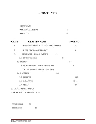
  • 1. CONTENTS CERTIFICATE i ACKNOWLEDGEMENT ii ABSTRACT iii Ch. No CHAPTER NAME PAGE NO 1 INTRODUCTION TO PLC BASED LOAD SHARING 2-3 2 BLOCK DIAGRAM OF PROJECT 4 3. HARDWARE REQUIREMENTS 5 3.1 TRANSFORMERS 5-7 3.2 DIODES 7 3.3 PROGRAMMABLE LOGIC CONTROLER 8 (ALLEN BRADLEY MICROLOGIX 1000) 3.4 RECTIFIER 8-9 3.5 RESISTOR 9-12 3.6 CAPACITOR 13-16 3.7 RELAY 17 3.8 LED/DC INDICATOR17-20 3.9DC MOTOR (12V 300RPM) CONCLUSION 21-22 23 REFERENCE DEPARTMENT OF EE, SKIT 24
  • 2. LIST OF FIGURE FIG. No 2(a) FIGURE NAME PAGE NO PLC BASED LOAD SHARING SYSTEM 4 3.1 A TYPICAL TRANSFORMER 5 3.2 A DIODE 7 3.3 A TYPICAL PLC 8 3.4CIRCUIT DIAGRAM AND WAVEFORM FOR BRIDGE RECTIFIER 9 3.5 VARIOUS TYPES OF RESISTOR 3.6(a) VARIOUS TYPES OF CAPACITOR 13 3.6(b) PARALLEL PLATE CAPACITOR 15 3.7(a) A TYPICAL 8 PIN RELAY 17 3.8(a) TYPICAL LED 18 3.8(b) CIRCUIT SYMBOL OF LED 18 3.8(c) DIFFERENT TYPES OF LED 19 3.9 A 12V 300 RPM DC MOTOR 21 DEPARTMENT OF EE/SKIT 10 Page 1
  • 3. CHAPTER 1 INTRODUCTION TO PLC BASED LOAD SHARING A Programmable Logic Controller, PLC or Programmable Controller is a digital computer used forautomation of electromechanical processes, such as control of machinery on factory assembly lines,amusement rides, or light fixtures. PLCs are used in many industries and machines. Unlike general-purpose computers, the PLC is designed for multiple inputs and output arrangements, extended temperature ranges, immunity to electrical noise, and resistance to vibration and impact. Programs to control machine operation are typically stored in battery-backed-up or nonvolatile memory. A PLC is an example of a hard real timesystem since output results must be produced in response to input conditions within a limited time, otherwise unintended operation will result. For supplying a load in excess of the rating of an existing transformer, two or more transformers may be connected in parallel with the existing transformer. The transformers are connected in parallel when load on one of the transformers is more than its capacity. The reliability is increased with parallel operation than to have single larger unit. The cost associated with maintaining the spares is less when two transformers are connected in parallel. It is usually economical to install another transformer in parallel instead of replacing the existing transformer by a single larger unit. The cost of a spare unit in the case of two parallel transformers (of equal rating) is also lower than that of a single large transformer. In addition, it is preferable to have a parallel transformer for the reason of reliability. With this at least half the load can be supplied with one transformer out of service. In this project we are designing a system which is capable of sharing loads among several installed sources. It means according to increased loads it automatically adds new sources of power and in case of decrement in loads sources will automatically cut out. There are three transformers working as sources in this project. At very first time 1st transformer is under working condition and it will be remain as it is till it continues DEPARTMENT OF EE/SKIT Page 2
  • 4. its supply. If any faults occurs and its supply to load is interrupted the second transformer will automatically come in role and the former one will be removed. Now take another case consider 1st transformer is in work and if increasing loads becomes more than its rated capacity the 2nd transformer will automatically be added in the circuit and for further loads next sources will be added and so on. And vice versa if load is decreased transformer will be removed. All this system is automated by using PLC (Programmable Logic Controller). We will program the PLC according to our requirement that will be capable of automatic switching of transformer circuits and will operate them. DEPARTMENT OF EE/SKIT Page 3
  • 5. CHAPTER 2 PROJECT BLOCK DIAGRAM FIG 2(a): PLC BASED LOAD SHARING SYSTEM DEPARTMENT OF EE/SKIT Page 4
  • 6. CHAPTER 3 HARDWARE REQUIREMENTS 3.1 TRANSFORMER Transformers convert AC electricity from one voltage to another with a little loss of power. Step-up transformers increase voltage, step-down transformers reduce voltage. Most power supplies use a step-down transformer to reduce the dangerously high voltage to a safer low voltage. FIG 3.1: A TYPICAL TRANSFORMER The input coil is called the primary and the output coil is called the secondary. There is no electrical connection between the two coils; instead they are linked by an alternating magnetic field created in the soft-iron core of the transformer. The two lines in the middle of the circuit symbol represent the core. Transformers waste very little power so the power out is (almost) equal to the power in. Note that as voltage is stepped down and current is stepped up. The ratio of the number of turns on each coil, called the turn’s ratio, determines the ratio of the voltages. A step-down transformer has a large number of turns on its primary (input) coil which is connected to the high voltage mains supply, and a small number of turns on its secondary (output) coil to give a low output voltage. TURNS RATIO = (Vp / Vs) = ( Np / Ns ) Where, Vp = primary (input) voltage. DEPARTMENT OF EE/SKIT Page 5
  • 7. Vs = secondary (output) voltage Np = number of turns on primary coil Ns = number of turns on secondary coil Ip = primary (input) current Is = secondary (output) current. Ideal power equation The ideal transformer as a circuit element If the secondary coil is attached to a load that allows current to flow, electrical power is transmitted from the primary circuit to the secondary circuit. Ideally, the transformer is perfectly efficient; all the incoming energy is transformed from the primary circuit to the magnetic field and into the secondary circuit. If this condition is met, the incoming electric power must equal the outgoing power: Giving the ideal transformer equation Transformers normally have high efficiency, so this formula is a reasonable approximation. If the voltage is increased, then the current is decreased by the same factor. The impedance in one circuit is transformed by the square of the turn’s ratio.For example, if an impedance Zs is DEPARTMENT OF EE/SKIT Page 6
  • 8. attached across the terminals of the secondary coil, it appears to the primary circuit to have an impedance of (Np/Ns)2Zs. This relationship is reciprocal, so that the impedance Zp of the primary circuit appears to the secondary to be (Ns/Np)2Zp. 3.2DIODE FIG 3.2: A DIODE Diodes are components that allow current to flow in only one direction. They have a positive side (leg) and a negative side. When the voltage on the positive leg is higher than on the negative leg then current flows through the diode (the resistance is very low). When the voltage is lower on the positive leg than on the negative leg then the current does not flow (the resistance is very high). The negative leg of a diode is the one with the line closest to it. It is called the cathode. The positive end is called the anode. Usually when current is flowing through a diode, the voltage on the positive leg is 0.65 volts higher than on the negative leg. DEPARTMENT OF EE/SKIT Page 7
  • 9. 3.3 PROGRAMMABLE LOGIC CONTROLLER FIG 3.3: A TYPICAL PLC A Programmable Logic Controller, PLC or Programmable Controller is a digital computer used for automation of electromechanical processes, such as control of machinery on factory assembly lines, amusement rides, or light fixtures. PLCs are used in many industries and machines. Unlike general-purpose computers, the PLC is designed for multiple inputs and output arrangements, extended temperature ranges, immunity to electrical noise, and resistance to vibration and impact. Programs to control machine operation are typically stored in battery-backed-up or nonvolatile memory. A PLC is an example of a hard real time system since output results must be produced in response to input conditions within a limited time, otherwise unintended operation will result. 3.4RECTIFIER A rectifier is an electrical device that converts alternating current (AC), which periodically reverses direction, to direct current (DC), current that flows in only one direction, a process known as rectification. Rectifiers have many uses including as components of power supplies and as detectors of radio signals. Rectifiers may be made of solid statediodes, vacuum DEPARTMENT OF EE/SKIT Page 8
  • 10. tube diodes, mercury arc valves, and other components. The output from the transformer is fed to the rectifier. It converts A.C. into pulsating D.C. The rectifier may be a half wave or a full wave rectifier. In this project, a bridge rectifier is used because of its merits like good stability and full wave rectification. In positive half cycleonly two diodes( 1 set of parallel diodes) will conduct, in negative half cycle remaining two diodes will conduct and they will conduct only in forward bias only. FIG3.4: CIRCUIT DIAGRAM AND WAVEFORM FOR BRIDGE RECTIFIER 3.5 RESISTOR A resistor is a two-terminal electronic component designed to oppose an electric current by producing a voltage drop between its terminals in proportion to the current, that is, in accordance with Ohm's law: V = IR Resistors are used as part of electrical networks and electronic circuits. They are extremely commonplace in most electronic equipment. Practical resistors can be made of various DEPARTMENT OF EE/SKIT Page 9
  • 11. compounds and films, as well as resistance wire (wire made of a high-resistivity alloy, such as nickel/chrome). The primary characteristics of resistors are their resistance and the power they can dissipate. Other characteristics include temperature coefficient, noise, and inductance. Less wellknown is critical resistance, the value below which power dissipation limits the maximum permitted current flow, and above which the limit is applied voltage. Critical resistance depends upon the materials constituting the resistor as well as its physical dimensions; it's determined by design. Resistors can be integrated into hybrid and printed circuits, as well as integrated circuits. Size, and position of leads (or terminals) are relevant to equipment designers; resistors must be physically large enough not to overheat when dissipating their power. FIG 3.5: VARIOUS TYPES OF RESISTOR A resistor is a two-terminalpassiveelectronic component which implements electrical resistance as a circuit element. When a voltage V is applied across the terminals of a resistor, a current I will flow through the resistor in direct proportion to that voltage. The reciprocal of the constant of proportionality is known as the resistance R, since, with a given voltage V, a larger value of R further "resists" the flow of current I as given by Ohm's law: DEPARTMENT OF EE/SKIT Page 10
  • 12. Resistors are common elements of electrical networks and electronic circuits and are ubiquitous in most electronic equipment. Practical resistors can be made of various compounds and films, as well as resistance wire (wire made of a high-resistivity alloy, such as nickelchrome). Resistors are also implemented within integrated circuits, particularly analog devices, and can also be integrated into hybrid and printed circuits. The electrical functionality of a resistor is specified by its resistance: common commercial resistors are manufactured over a range of more than 9 orders of magnitude. When specifying that resistance in an electronic design, the required precision of the resistance may require attention to the manufacturing tolerance of the chosen resistor, according to its specific application. The temperature coefficient of the resistance may also be of concern in some precision applications. Practical resistors are also specified as having a maximum power rating which must exceed the anticipated power dissipation of that resistor in a particular circuit: this is mainly of concern in power electronics applications. Resistors with higher power ratings are physically larger and may require heat sinking. In a high voltage circuit, attention must sometimes be paid to the rated maximum working voltage of the resistor. The series inductance of a practical resistor causes its behavior to depart from ohms law; this specification can be important in some high-frequency applications for smaller values of resistance. In a low-noise amplifier or pre-amp the noise characteristics of a resistor may be an issue. The unwanted inductance, excess noise, and temperature coefficient are mainly dependent on the technology used in manufacturing the resistor. They are not normally specified individually for a particular family of resistors manufactured using a particular technology. A family of discrete resistors is also characterized according to its form factor, that is, the size of the device and position of its leads (or terminals) which is relevant in the practical manufacturing of circuits using them. Units The ohm (symbol: Ω) is the SI unit of electrical resistance, named after Georg Simon Ohm. An ohm is equivalent to a volt per ampere. Since resistors are specified and manufactured DEPARTMENT OF EE/SKIT Page 11
  • 13. over a very large range of values, the derived units of milliohm (1 mΩ = 10−3 Ω), kilohm (1 kΩ = 103 Ω), and megohm (1 MΩ = 106 Ω) are also in common usage. The reciprocal of resistance R is called conductance G = 1/R and is measured in Siemens (SI unit), sometimes referred to as a mho. Thus a Siemens is the reciprocal of an ohm: S = Ω − 1. Although the concept of conductance is often used in circuit analysis, practical resistors are always specified in terms of their resistance (ohms) rather than conductance. Variable resistors Adjustable resistors A resistor may have one or more fixed tapping points so that the resistance can be changed by moving the connecting wires to different terminals. Some wirewound power resistors have a tapping point that can slide along the resistance element, allowing a larger or smaller part of the resistance to be used. Where continuous adjustment of the resistance value during operation of equipment is required, the sliding resistance tap can be connected to a knob accessible to an operator. Such a device is called a rheostat and has two terminals. Potentiometers A common element in electronic devices is a three-terminal resistor with a continuously adjustable tapping point controlled by rotation of a shaft or knob. These variable resistors are known as potentiometers when all three terminals are present, since they act as a continuously adjustable voltage divider. A common example is a volume control for a radio receiver. Accurate, high-resolution panel-mounted potentiometers (or "pots") have resistance elements typically wire wound on a helical mandrel, although some include a conductive-plastic resistance coating over the wire to improve resolution. These typically offer ten turns of their shafts to cover their full range. They are usually set with dials that include a simple turns counter and a graduated dial. Electronic analog computers used them in quantity for setting coefficients, and delayed-sweep oscilloscopes of recent decades included one on their panels. DEPARTMENT OF EE/SKIT Page 12
  • 14. 3.6 CAPACITOR A capacitor or condenser is a passive electronic component consisting of a pair of conductors separated by a dielectric. When a voltage potential difference exists between the conductors, an electric field is present in the dielectric. This field stores energy and produces a mechanical force between the plates. The effect is greatest between wide, flat, parallel, narrowly separated conductors. An ideal capacitor is characterized by a single constant value, capacitance, which is measured in farads. This is the ratio of the electric charge on each conductor to the potential difference between them. In practice, the dielectric between the plates passes a small amount of leakage current. The conductors and leads introduce an equivalent series resistance and the dielectric has an electric field strength limit resulting in a breakdown voltage. The properties of capacitors in a circuit may determine the resonant frequency and quality factor of a resonant circuit, power dissipation and operating frequency in a digital logic circuit, energy capacity in a high-power system, and many other important aspects. FIG 3.6(a): VARIOUS TYPES OF CAPACITORS DEPARTMENT OF EE/SKIT Page 13
  • 15. A capacitor (formerly known as condenser) is a device for storing electric charge. The forms of practical capacitors vary widely, but all contain at least two conductors separated by a non-conductor. Capacitors used as parts of electrical systems, for example, consist of metal foils separated by a layer of insulating film. Capacitors are widely used in electronic circuits for blocking direct current while allowing alternating current to pass, in filter networks, for smoothing the output of power supplies, in the resonant circuits that tune radios to particular frequencies and for many other purposes. A capacitor is a passiveelectronic component consisting of a pair of conductors separated by a dielectric (insulator). When there is a potential difference (voltage) across the conductors, a static electric field develops in the dielectric that stores energy and produces a mechanical force between the conductors. An ideal capacitor is characterized by a single constant value, capacitance, measured in farads. This is the ratio of the electric charge on each conductor to the potential difference between them. The capacitance is greatest when there is a narrow separation between large areas of conductor, hence capacitor conductors are often called "plates", referring to an early means of construction. In practice the dielectric between the plates passes a small amount of leakage current and also has an electric field strength limit, resulting in a breakdown voltage, while the conductors and leads introduce an undesired inductance and resistance. Theory of operation Capacitance DEPARTMENT OF EE/SKIT Page 14
  • 16. Charge separation in a parallel-plate capacitor causes an internal electric field. A dielectric (orange) reduces the field and increases the capacitance. FIG 3.6(b): PARALLEL PLATE CAPACITOR A simple demonstration of a parallel-plate capacitor A capacitor consists of two conductors separated by a non-conductive region. The nonconductive region is called the dielectric or sometimes the dielectric medium. In simpler terms, the dielectric is just an electrical insulator. Examples of dielectric mediums are glass, air, paper, vacuum, and even a semiconductordepletion region chemically identical to the conductors. A capacitor is assumed to be self-contained and isolated, with no net electric charge and no influence from any external electric field. The conductors thus hold equal and opposite charges on their facing surfaces, and the dielectric develops an electric field. In SI units, a capacitance of one farad means that one coulomb of charge on each conductor causes a voltage of one volt across the device. The capacitor is a reasonably general model for electric fields within electric circuits. An ideal capacitor is wholly characterized by a constant capacitance C, defined as the ratio of charge ±Q on each conductor to the voltage V between them: Sometimes charge build-up affects the capacitor mechanically, causing its capacitance to vary. In this case, capacitance is defined in terms of incremental changes: DEPARTMENT OF EE/SKIT Page 15
  • 17. Energy storage Work must be done by an external influence to "move" charge between the conductors in a capacitor. When the external influence is removed the charge separation persists in the electric field and energy is stored to be released when the charge is allowed to return to its equilibrium position. The work done in establishing the electric field, and hence the amount of energy stored, is given by: Current-voltage relation The current i(t) through any component in an electric circuit is defined as the rate of flow of a charge q(t) passing through it, but actual charges, electrons, cannot pass through the dielectric layer of a capacitor, rather an electron accumulates on the negative plate for each one that leaves the positive plate, resulting in an electron depletion and consequent positive charge on one electrode that is equal and opposite to the accumulated negative charge on the other. Thus the charge on the electrodes is equal to the integral of the current as well as proportional to the voltage as discussed above. As with any antiderivative, a constant of integration is added to represent the initial voltage v (t0). This is the integral form of the capacitor equation, . Taking the derivative of this, and multiplying by C, yields the derivative form, . The dual of the capacitor is the inductor, which stores energy in the magnetic field rather than the electric field. Its current-voltage relation is obtained by exchanging current and voltage in the capacitor equations and replacing C with the inductance L. DEPARTMENT OF EE/SKIT Page 16
  • 18. 3.7 RELAY FIG 3.7: A TYPICAL 8 PIN RELAY A relay is an electrically operated switch. Many relays use an electromagnet to operate a switching mechanism mechanically, but other operating principles are also used. Relays are used where it is necessary to control a circuit by a low-power signal (with complete electrical isolation between control and controlled circuits), or where several circuits must be controlled by one signal. The first relays were used in long distance telegraph circuits, repeating the signal coming in from one circuit and re-transmitting it to another. Relays were used extensively in telephone exchanges and early computers to perform logical operations. A type of relay that can handle the high power required to directly control an electric motor or other loads is called a contactor. Solid-state relays control power circuits with no moving parts, instead using a semiconductor device to perform switching. Relays with calibrated operating characteristics and sometimes multiple operating coils are used to protect electrical circuits from overload or faults; in modern electric power systems these functions are performed by digital instruments still called "protective relays". 3.8 LED LEDs are semiconductor devices. Like transistors, and other diodes, LEDs are made out of silicon. What makes an LED give off light are the small amounts of chemical impurities that are added to the silicon, such as gallium, arsenide, indium, and nitride. DEPARTMENT OF EE/SKIT Page 17
  • 19. When current passes through the LED, it emits photons as a byproduct. Normal light bulbs produce light by heating a metal filament until it is white hot. LEDs produce photons directly and not via heat, they are far more efficient than incandescent bulbs. FIG 3.8(a): TYPICAL LED FIG 3.8(b): CIRCUIT SYMBOL OF LED Not long ago LEDs were only bright enough to be used as indicators on dashboards or electronic equipment. But recent advances have made LEDs bright enough to rival traditional lighting technologies. Modern LEDs can replace incandescent bulbs in almost any application. Types of LED’S LEDs are produced in an array of shapes and sizes. The 5 mm cylindrical package is the most common, estimated at 80% of world production. The color of the plastic lens is often the same as the actual color of light emitted, but not always. For instance, purple plastic is often used for infrared LEDs, and most blue devices have clear housings. There are also LEDs in extremely tiny packages, such as those found on blinkers and on cell phone keypads. The main types of LEDs are miniature, high power devices and custom designs such as alphanumeric or multi-color. DEPARTMENT OF EE/SKIT Page 18
  • 20. Fig 3.8(c) DIFFERENT TYPES OF LED’S Colors and materials of LED’S Conventional LED’S are made from a variety of inorganic semiconductor materials, the following table shows the available colours with wavelength range, voltage drop and material. White LED’S Light Emitting Diodes (LED) have recently become available that are white and bright, so bright that they seriously compete with incandescent lamps in lighting applications. They are still pretty expensive as compared to a GOW lamp but draw much less current and project a fairly well focused beam. The diode in the photo came with a neat little reflector that tends to sharpen the beam a little but doesn't seem to add much to the overall intensity. When run within their ratings, they are more reliable than lamps as well. Red LEDs are now being used in automotive and truck tail lights and in red traffic signal lights. You will be DEPARTMENT OF EE/SKIT Page 19
  • 21. able to detect them because they look like an array of point sources and they go on and off instantly as compared to conventional incandescent lamps. LEDs are monochromatic (one color) devices. The color is determined by the band gap of the semiconductor used to make them. Red, green, yellow and blue LEDs are fairly common. White light contains all colors and cannot be directly created by a single LED. The most common form of "white" LED really isn't white. It is a Gallium Nitride blue LED coated with a phosphor that, when excited by the blue LED light, emits a broad range spectrum that in addition to the blue emission, makes a fairly white light. There is a claim that these white LED's have a limited life. After 1000 hours or so of operation, they tend to yellow and dim to some extent. Running the LEDs at more than their rated current will certainly accelerate this process. There are two primary ways of producing high intensity white-light using LED’S. One is to use individual LED’S that emit three primary colours—red, green, and blue—and then mix all the colours to form white light. The other is to use a phosphor material to convert monochromatic light from a blue or UV LED to broad-spectrum white light, much in the same DEPARTMENT OF EE/SKIT Page 20
  • 22. way a fluorescent light bulb works. Due to metamerism, it is possible to have quite different spectra that appear white 3.9 DC MOTOR FIG 3.9: A 12V 300RPM DC MOTOR A DC motor is a mechanically commutated electric motor powered from direct current (DC). The stator is stationary in space by definition and therefore the current in the rotor is switched by the commutator to also be stationary in space. This is how the relative angle between the stator and rotor magnetic flux is maintained near 90 degrees, which generates the maximum torque. DC motors have a rotating armature winding (winding in which a voltage is induced) but nonrotating armature magnetic field and a static field winding (winding that produce the main magnetic flux) or permanent magnet. Different connections of the field and armature winding provide different inherent speed/torque regulation characteristics. The speed of a DC motor can DEPARTMENT OF EE/SKIT Page 21
  • 23. be controlled by changing the voltage applied to the armature or by changing the field current. The introduction of variable resistance in the armature circuit or field circuit allowed speed control. Modern DC motors are often controlled by power electronics systems called DC drives. The introduction of DC motors to run machinery eliminated the need for local steam or internal combustion engines, and line shaft drive systems. DC motors can operate directly from rechargeable batteries, providing the motive power for the first electric vehicles. Today DC motors are still found in applications as small as toys and disk drives, or in large sizes to operate steel rolling mills and paper machines. DEPARTMENT OF EE/SKIT Page 22
  • 24. CONCLUSION This report is prepared on the basis of study of theproject PLC BASED LOAD SHARING. For supplying a load in excess of the rating of an existing transformer, two or more transformers may be connected in parallel with the existing transformer. The transformers are connected in parallel when load on one of the transformers is more than its capacity. The entire process can be controlled using a programmable logic controller i.e a PLC. The reliability is increased with parallel operation than to have single larger unit also the cost associated with maintaining the spares is less when two transformers are connected in parallel. The most important aspect during ourproject was to study the sharing of load between transformers,During this time I was able to relate the theoretical part to the practical. This project as a whole proved to be extremely informative and experience building and things learnt would help a lot in snapping the future ahead a better way. DEPARTMENT OF EE/SKIT Page 23
  • 25. REFERENCE TEXT BOOKS REFERED: 1. “Electrical power system ” by Ashfaq Husain, CVS Publications. 2. “Modern Power System Analysis”by D P Kothari and I G Nagrath, Mc Graw Hill Education WEBSITES www.britannica.com www.beyondlogic.org www.wikipedia.org www.howstuffworks.com www.alldatasheets.com DEPARTMENT OF EE/SKIT Page 24