Más contenido relacionado
La actualidad más candente (20)
Similar a emulation of wireless networks (20)
emulation of wireless networks
- 1. A Dynamic Topology Switch for the Emulation of
Wireless Mobile Ad Hoc Networks
Tao Lin Scott F. Midkiff Jahng S. Park
taolin@vt.edu midkiff@vt.edu jahng@vt.edu
Bradley Department of Electrical and Computer Engineering
Virginia Polytechnic Institute and State University
Blacksburg, Virginia 24061 USA
Abstract
Wireless mobile ad hoc networks differ from wired
networks in that their topologies are highly dynamic and
their links can have a relatively high bit error rate. These
properties make it difficult to conduct controlled,
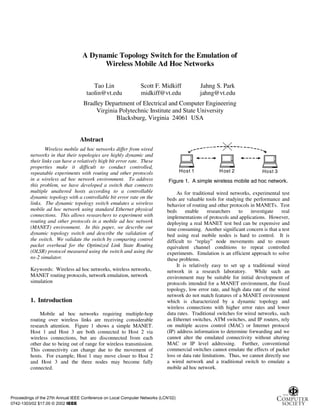
repeatable experiments with routing and other protocols Host 1 H ost 2 Host 3
in a wireless ad hoc network environment. To address Figure 1. A simple wireless mobile ad hoc network.
this problem, we have developed a switch that connects
multiple unaltered hosts according to a controllable As for traditional wired networks, experimental test
dynamic topology with a controllable bit error rate on the beds are valuable tools for studying the performance and
links. The dynamic topology switch emulates a wireless behavior of routing and other protocols in MANETs. Test
mobile ad hoc network using standard Ethernet physical beds enable researchers to investigate real
connections. This allows researchers to experiment with implementations of protocols and applications. However,
routing and other protocols in a mobile ad hoc network deploying a real MANET test bed can be expensive and
(MANET) environment. In this paper, we describe our time consuming. Another significant concern is that a test
dynamic topology switch and describe the validation of bed using real mobile nodes is hard to control. It is
the switch. We validate the switch by comparing control difficult to “replay” node movements and to ensure
packet overhead for the Optimized Link State Routing equivalent channel conditions to repeat controlled
(OLSR) protocol measured using the switch and using the experiments. Emulation is an efficient approach to solve
ns-2 simulator. these problems.
It is relatively easy to set up a traditional wired
Keywords: Wireless ad hoc networks, wireless networks, network in a research laboratory. While such an
MANET routing protocols, network emulation, network environment may be suitable for initial development of
simulation protocols intended for a MANET environment, the fixed
topology, low error rate, and high data rate of the wired
network do not match features of a MANET environment
1. Introduction which is characterized by a dynamic topology and
wireless connections with higher error rates and lower
Mobile ad hoc networks requiring multiple-hop data rates. Traditional switches for wired networks, such
routing over wireless links are receiving considerable as Ethernet switches, ATM switches, and IP routers, rely
research attention. Figure 1 shows a simple MANET. on multiple access control (MAC) or Internet protocol
Host 1 and Host 3 are both connected to Host 2 via (IP) address information to determine forwarding and we
wireless connections, but are disconnected from each cannot alter the emulated connectivity without altering
other due to being out of range for wireless transmission. MAC or IP level addressing. Further, conventional
This connectivity can change due to the movement of commercial switches cannot emulate the effects of packet
hosts. For example, Host 1 may move closer to Host 2 loss or data rate limitations. Thus, we cannot directly use
and Host 3 and the three nodes may become fully a wired network and a traditional switch to emulate a
connected. mobile ad hoc network.
Proceedings of the 27th Annual IEEE Conference on Local Computer Networks (LCN’02)
0742-1303/02 $17.00 © 2002 IEEE
- 2. To meet this need, we have developed a special Fe(⋅) maps the coordinates of two hosts to a connection
switch that connects multiple hosts according to a status value for a given environment e. Fe(⋅) is a complex
controllable dynamic topology with a controllable bit function that depends on a variety of functions such as
error rate and a controllable data rate on the links. Our radios, anntenas, coding, transmit power, capture effects,
dynamic topology switch is implemented in the Linux long-term fading effects, terrain, and atmospheric
operating system and includes modifications to the Linux conditions. The dynamic topology switch does not
kernel. The switch emulates a MANET using standard evaluate the connectivity function, but rather relies on an
Ethernet or other wired physical connections and requires external source to specify the connectivity, Ci,j(t), for all
no changes to the network’s hosts. pairs of nodes, i and j, as a function of time. This
Our primary objective was to create a reasonable information can be derived from a mobility simulation,
emulation of a MANET environment that required no which has been our approach, or by some other trace file
changes to the mobile nodes. We want to test different that might be based on measurements of a physical
types of mobile nodes, including nodes running system or derived in some other way.
proprietary operating systems. We also want to make the The basic concept of operation for the dynamic
emulation “transparent” to the real protocols. This topology switch is to control the connectivity of “mobile”
transparency includes both functional transparency as a nodes using the central hub in a star network. Figure 2
first priority and performance transparency, at least to the shows a simple example with three mobile nodes and a
extent permitted by the emulated environment, as a single dynamic topology switch. The mobile nodes can
second priority. This requires that the switch achieve be any device running any software, as long as they have
high performance to match wireless link data rates, an appropriate network interface card. The switch is
including for new higher data rate wireless local area implemented with an industry-standard personal computer
network standards such as IEEE 802.11a and IEEE running Linux. It has multiple network interfaces, e.g., by
802.11g. We also wanted to use standard “off-the-shelf” using multiple interface cards and/or multiple-port
personal computers for the switch and, clearly, needed an interface cards. Implementation details and related
open source operating system. performance issues are provided in Sections 3 and 4,
In Section 2 of this paper, we describe a model to respectively.
emulate the topology changes, bit error rate, and data rate
of a MANET environment using a wired network. In Host 1
Section 3, we discuss the implementation of the model as
the dynamic topology switch. Section 4 presents the
partial validation of the emulator through comparisons D y n a m ic
with ns-2 simulation results for the OLSR MANET S w itc h
routing protocol. Section 5 compares our dynamic Host 2 H o st 3
topology switch to related work in network emulation.
Section 6 presents conclusions and directions for future
work. Figure 2. Example test network.
2. Model description The dynamic topology switch can switch traffic
between any set of connected hosts, based on a local
switch connectivity table that can change dynamically.
2.1. Emulation of a dynamic topology The switch is transparent to all the other nodes at and
above the MAC layer. All incoming frames are switched
In a wireless network, a host can transmit directly to based solely on the input interface and the switch
another host only if the receiving host is within a certain connectivity table information. The switch does not alter
range of the sending host. Because hosts in a MANET the MAC frame or IP datagram information in anyway
can be mobile, the connectivity of the network can change and, in particular, it does not add any address information
at any time. Conceptually, this dynamic connectivity can of its own to the MAC frame or IP datagram. Hosts
be described by a function of time and location, as shown receive packets from all current neighbors, including
in Equation 1. packets not addressed to the host, thus enabling use of
C i, j (t ) = Fe ( x (t ), y (t ) ,
i i x j (t ), y j (t ) ) (1)
packet filtering, snooping, and other routing functions at
the hosts.
Table 1 shows an example switch connectivity table.
Here, Ci,j(t) represents the status of the connection
Note that the ports in the table denote the network
between hosts i and j. If hosts i and j are connected, then
interface ports of the dynamic topology switch. In other
Ci,j(t) = 1. If they are disconnected, then Ci,j(t) = 0. The
words, the switch relies on incoming or outgoing network
coordinates of host i at time t are <xi(t),yi(t)>. Function
Proceedings of the 27th Annual IEEE Conference on Local Computer Networks (LCN’02)
0742-1303/02 $17.00 © 2002 IEEE
- 3. interfaces, not the MAC or IP addresses, to specify
forwarding. The example switch connectivity table in 2.3. Emulation of constrained capacity
Table 1 emulates the wireless ad hoc network shown in
Figure 1 where Hosts 1 and 3 are connected to Host 2, but The capacity of wireless links may be less than the
not to each other. capacity of the wired links used in the test bed. We
The dynamic topology switch can update the switch enforce constraints on available bandwidth using a leaky-
connectivity table in real time. Specifically, the bucket token buffer model.
connectivity table can be changed as a function of time, In the leaky-bucket token buffer model, no packet
with the temporal accuracy limited only by the can be sent unless there is a token in the token buffer or a
responsiveness of the host operating system at the new token arrives. There is an upper bound on the size of
dyanmic switch. Thus, we can, in effect, generate a the token buffer. We use a token arrival rate of r tokens
sequence of switch connectivity tables to emulate the per second, a token buffer size of B tokens, and an
connectivity of a mobile ad hoc network that changes as a allowable transmission size of µ bytes per token to
function of time. determine the bandwidth constraint [2]. Equation 2
specifies the maximum allowable data rate, where C is the
Table 1. Example connectivity table transmission rate or emulated capacity.
C = µ × r bytes per second (2)
Incoming port Host 1 Host 2 Host 3
Since the emulated system does not accumulate
Host 1 transmission “credits,” i.e., there is no history, we use
Outgoing port(s) Host 2 Host 2
Host 3 buffer size B = 1. Selection of r involves a tradeoff
between accuracy and processing overhead. A high token
arrival rate r results in transmissions being spread out
2.2. Emulation of packet drops over a longer interval that more closely mimics a low data
rate link. However, we need to reduce r due to the
Mobile ad hoc networks are implemented using minimum timer interval supported by the operating
wireless communications where packet drops due to bit system of the switch host and the desire to reduce timer
errors may be likely. In the dynamic topology switch, we interupt overhead. Based on tests, we found a suitable
control the packet drop rate for each connected channel. token arrival rate to be r = 1,000 tokens per second. Thus,
We use the Gilbert model [1], a two-state discrete-time the allowable transmission size per token is selected to be
Markov model, for packet drops. Other models could be µ = C/1000 bytes.
realized, e.g., to model short-term fades or random packet
capture effects.
3. Implementation
1-P1 We developed the dynamic topology switch in
P1 P2 Redhat 7.0 with Linux kernel 2.2.16. Users need to have
Good Bad root privileges to install the code into a Linux system.
Installation requires re-compilation of the kernel. Source
1-P2 code is available under the GNU copyright.†
The software can be divided into three parts: user
Figure 3. Two-state Markov chain for packet drop space program, broker program, and kernel space
process. program. The user space program is responsible for
interactions with users. The kernel space program
In the two-state Markov model, a channel can be in handles kernel interruptions and received packets. The
one of two possible states, “good” or “bad.” The state broker program contains a character device driver, which
transition diagram is shown in Figure 3. The probability is used to exchange information between user space and
of dropping a packet, i.e., the probability of a packet error, kernel space.
is different in each state. PG is the probability of dropping The user space program first translates user inputs or
a packet while in the good state and PB, PB > PG, is the command files into the proper command format. The
probability of dropping a packet while in the bad state. translated commands are written into the character device
Given a present state, a channel may transfer to the other in the broker program. If users require debug information
state or stay in the present state with certain probabilities.
P1 and P2 are the transition probabilities of staying in the †
The source code can be downloaded from
good and bad states, respectively. http://www.sourceforge.net/projects/dynamic-switch.
Proceedings of the 27th Annual IEEE Conference on Local Computer Networks (LCN’02)
0742-1303/02 $17.00 © 2002 IEEE
- 4. from the kernel, the user space program sends the metric is independent of the specific underlying MAC
corresponding command to the broker program and reads protocol and should be consistent across the two
returned data from that character device. realizations. Some important metrics, such as end-to-end
The broker is a module that can be loaded in super- packet delay, cannot be used for validation since results
user mode. The broker creates a character device and sets depend on delays associated with the wireless MAC layer,
all network interfaces to promiscuous mode during which is not emulated in the dynamic topology switch.
initialization. The broker program also maintains the Parameters for the Linux implementation of OLSR
switch connectivity table and token buffer queues. It are the same as those for the ns-2 model of OLSR except
continues to listen for input/output interrupts from the for jitter time. The ns-2 model of OLSR introduces jitter
character device and calls the proper procedures to handle to slightly randomize the time at which control packets
requests from the user space program. This allows users are generated to reduce the likelihood of MAC-level
to use commands or input files to control the dynamic collisions. Without jitter, the tight synchronization of
topology switch as a function of time. The broker is also nodes in a simulation model would result in multiple
responsible for moving outgoing packets into the proper nodes attempting to transmit at the same time, thus
buffers of the network devices. leading to pessimistic performance because of an
The kernel space program deals with packet capture increased number of collisions. In a real network,
and dynamic forwarding. Once a packet is captured, the including the network emulated by the dynamic topology
kernel procedure enters the dynamic switch block if the switch, nodes are not tightly synchronized. Thus, the
character device driver is loaded. The kernel space jitter parameter in the ns-2 OLSR model accounts for the
program looks up the outgoing port(s) for each incoming jitter that occurs implicitly in a real system. The jitter
packet in the switch connectivity table via the broker parameter for the ns-2 model is set to 0.1 seconds based
program. The switch does not examine packets, but they on observations from the Linux implementation.
are duplicated if necessary so that one incoming packet We use the same mobility assumptions in both the
can be delivered to multiple output ports. The kernel dynamic topology switch and the ns-2 model. The
space program forwards packets to the proper devices mobility model considers a four-node network, with the
using the sending procedure in the broker program. mobile nodes moving in a 100-by-100 unit square map.
(All length and velocity parameters are normalized to
4. Model validation “units.”) Nodes start at random positions within this area.
Each node moves at a random speed for a random length
To at least partially determine the validity of the of time. Both the speed and the duration of the movement
dynamic topology switch for use in network performance are exponentially distributed. Nodes pause for a constant
studies, we compare measured values obtained using the time when movement ends. We assume that the previous
switch to those produced by a widely used network direction of movement for a node is θ. Its next direction
simulator. In particular, we compare results from an of movement is chosen uniformly from [θ – α, θ + α],
actual implementation of the Optimized Link State where α degrees is the maximum change (or “delta
Routing protocol [3] running on four “mobile” nodes degree”) in the direction of movement. Following the
connected via our switch to results from an OLSR work of Bettstetter [6], we allow nodes to bounce at the
simulation model running in the ns-2 network simulator borders instead of wrapping around or leaving the
[4] for the same configuration. network. The radio range of a node is used to decide the
Wireless routing protocols can be classified as either connectivity between all pairs of nodes. As described
proactive or reactive. Mobile nodes in a proactive routing below, we vary the radio range and examine its effect on
protocol periodically broadcast “hello” messages and link control message overhead.
state changes. Mobile nodes in a reactive protocol find a There are five parameters that characterize mobility
route to another node on-demand when that node is the with this model: average speed, average moving time,
destination of a data packet. OLSR, the protocol fixed pause time, α, and radio range. Initial experiments
considered here, is a proactive protocol. The authors of showed that changes in the radio range have the most
the OLSR protocol distribute both a Linux significant effect on the total number of control messages
implementation and an ns-2 model [5], which we believe sent by the nodes. Therefore, we experimented with
adds confidence that the real implementation and the ns-2 scenarios with different radio ranges from 20 to 90 units.
model are consistent. All parameter values are shown in Table 2.
Our dynamic topology switch only emulates topology The simulation time for all runs was 300 seconds.
changes and wireless channel properties, specifically the This simulation time was chosen since the initial test runs
bit error rate and transmission capacity. Therefore, we showed that longer simulation times over 300 seconds
use control message overhead as the basis for comparing gave similar results. Five replications were run for each
results from the emulation and the simulation. This set of parameters, with the random seed set to 1, 2, 3, 4,
Proceedings of the 27th Annual IEEE Conference on Local Computer Networks (LCN’02)
0742-1303/02 $17.00 © 2002 IEEE
- 5. and 5. Same node movement profiles without any user messages that are sent increases as the topology changes
data stream were applied to both ns-2 simulation and the more frequently. When the radio range is small, say 20
dynamic switch-based test bed. units, or large, say 90 units, results from the ns-2
simulation and the switch-based emulation show that the
Table 2. Mobility parameters used for the number of control messages is relatively small and, thus,
experiments the network topologies change infrequently. For short
radio ranges, nodes are almost always disconnected from
Pause time 10 seconds their neighbors, i.e., there are few viable links, and
Average speed 20 units/second mobility leads to few changes in the topology. For long
radio ranges, nodes are usually connected to other nodes
Average movement time 10 seconds and extreme movements are needed to break a link.
α 0.0001 degrees When the radio ranges are from 40 to 80 units, the
network topology changes more frequently and both the
Radio range 20–90 units ns-2 simulation and switch-based emulation results
indicate that more control messages are sent.
The four graphs in Figure 4 show results from both Results for Node 1 are presented in Table 3. (Results
the ns-2 simulation and the dynamic switch-based from the other three nodes are similar.) The difference, as
emulation for each of the four nodes. Each point a percentage, between results for the ns-2 simulation and
represents the average of the values from the five the switch-based emulation is calculated as the difference
replications. between the number of control messages reported by each
For OLSR and other MANET routing protocols, method divided by the number of control messages
especially those that are proactive, the number of control reported by the ns-2 simulation. The percentage
No. of Sent Messages at Node 1 No. of Sent Messages at Node 2
175 175
No. of Sent Messages
No. of Sent Messages
170 170
165 165
160 160
155 155
150 150
NS 2 NS 2
145 145
140 DS testbed 140 DS testbed
135 135
20 30 40 50 60 70 80 90 20 30 40 50 60 70 80 90
Radio Range (unit) Radio Range (unit)
No. of Sent Messages at Node 3 No. of Sent Messages at Node 4
170 175
No. of Sent Messages
No. of Sent Messages
165 170
160 165
160
155
155
150
150
145 NS 2 NS 2
145
140 DS testbed 140 DS testbed
135 135
20 30 40 50 60 70 80 90 20 30 40 50 60 70 80 90
Radio Range (unit) Radio Range (unit)
Figure 4. Number of control messages versus radio range for Nodes 1 to 4.
Proceedings of the 27th Annual IEEE Conference on Local Computer Networks (LCN’02)
0742-1303/02 $17.00 © 2002 IEEE
- 6. difference is less than 7 percent for all values of radio
range. This small difference may be accounted for by the 5. Comparison to prior work
jitter parameter setting in the ns-2 simulation model or by
practical differences between the real implementation and There are other approaches that combine physical
the ns-2 model of OLSR. For example, all nodes are implementations of protocols with network emulation in
identical in ns-2, while processing delays may not be the different ways. However, these approaches have
same for all nodes in the switch-based emulation. Based somewhat different objectives.
on the close correspondence between results for the Nguyen, et al. [9] collect traces from physical
dynamic topology switch and ns-2 simulation, we have a systems for the purpose of modeling the behavior of
high level of confidence that the switch is accurately wireless channels. Simulation is used to compare results
emulating the topology of a mobile ad hoc network. using the traces to results using the derived model. The
objective was to build a wireless channel model for use
Table 3. Results from ns-2 and switch-based with simulation, which is different from the objective of
emulation for Node 1 our work in that we want to emulate the underlying
network and utilize actual nodes running actual protocol
Radio No. of No. of Percentage stacks.
Range Messages Messages Difference Noble, et al. [10] extend the work of Nguyen, et al.
(units) for ns-2 for Switch (%) [9] to create an approach they call “trace modulation.”
Traces are first collected from a physical system. The
20 148.4 150.0 1.08 traces are then distilled to build a network model that is
representative of the physical wireless mobile ad hoc
30 155.6 152.2 2.19 environment that was measured. Finally, the distilled
40 162.8 156.6 3.81 model is used to modulate the behavior of the protocol
stack in a physical system. A modulation layer is inserted
50 167.2 162.8 2.63 between the IP and Ethernet layers. The modulation layer
60 170.4 159.2 6.57 delays and drops packets according to the model derived
from the trace. A special process running on each node
70 166.0 158.2 4.70 supplies the modulation layer with time-varying
parameter values. This approach has been shown to be
80 161.2 152.4 5.46 effective for evaluating throughput, but temporal ordering
90 153.0 149.8 2.09 is affected so it is not useful for considering detail effects
of latency [11]. Trace modulation within the protocol
stack can provide higher fidelity than our system, but
As indicated in Section 3, we use Redhat 7.0 with
requires altering the operating system kernel of the mobile
Linux kernel 2.2.16 as the operating system in the
nodes. With our centralized dynamic switch, we move
dynamic topology switch. We use three ZNYX network
the locus of control for modulation outside of the mobile
cards [7], with each card containing four 10-Mbps
nodes, but do lose some fidelity in the process. However,
Ethernet ports. Testing showed that one Linux host can
extensions to our approach could provide similar fidelity.
support up to 10 ports. The actual performance that is
An extension of trace modulation is called “trace
achieveable by the dynamic topology switch depends on
emulation” by Johnson [11]. In trace emulation, the trace
the specific hardware configuration, including factors
of the network’s behavior is generated through simulation
such as processor clock rate, bus throughput, and memory
rather than experiments with a physical system.
size. Experiments are underway to determine maximum
Generating the trace file through simulation is comparable
throughput for the switch.
to our approach of using a mobility simulator to generate
In addition to using ports to connect mobile hosts, the
a trace file that controls the dynamic topology switch.
dynamic topology switch is able to receive normal
The generated trace is applied to the modulation layer as
network traffic on a designated interface. This allows us
in Noble, et al. [10] and, thus, requires modification of the
to exchange messages with mobile hosts to synchronize
mobile node’s kernel.
the overall system for testing purposes. For example, to
Johnson also developed a “direct emulation” method
generate repeatable experiments with reactive routing
[11] that is similar to our approach. As in our system,
protocols, we need to synchronize topology changes at the
packets from a real system are sent to a centralized host.
switch with startup activities at the mobile hosts. Using
The centralized host is running a simulation model that
this approach, we plan to compare emulation and
controls the dropping and delaying of packets. There is a
simulation results for the Dynamic Source Routing (DSR)
fundamental trade-off between fidelity and efficiency.
protocol [8].
Direct emulation provides greater fidelity than our
Proceedings of the 27th Annual IEEE Conference on Local Computer Networks (LCN’02)
0742-1303/02 $17.00 © 2002 IEEE
- 7. dynamic topology switch, but at the cost of extra Future work may, also, include extending this model
overhead that can reduce the supported data rate for each to consider the influence of the MAC layer and to
mobile node and/or limit the number of mobile nodes that controlling the data rate at the mobile node rather than at
can utilize the emulated network. Our scheme needs to the dynamic topology switch. This extension would, for
execute very little code to move a packet from an input example, allow consideration of end-to-end delay and
port to zero or more output ports. other relevant metrics. Note that MAC layer modeling
Direct emulation is similar to Fall’s use of the ns and bandwidth control at the mobile node extend
network simulator for emulation of traditional networks emulation capability from the switch to the mobile nodes.
[12] and to work by Xu, et al. where physical elements This violates our goal of allowing use of unaltered mobile
are integrated with a sensor network simulation running in nodes, but there may be experiments where changes to the
the GloMoSim simulator [13]. Fall’s approach and Xu’s mobile nodes are justified to increase fidelity. The
approach both require extra overhead to manage the fidelity of the emulation can be improved, for example,
interface between the physical device and the simulation through the introduction of delays in the switch. Since
model. For example, in Fall’s ns-based system, packets this extra processing could create a bottleneck at the
from real systems must be encapsulated as they are switch, it could also run counter to our overall objectives.
processed by the simulator to ensure that all packet Future work might also include testing with larger
information is preserved. In our approach and Johnson’s networks. In theory, the size of the emulated network
[11], this interface overhead is eliminated. could be scaled to an arbitrarily large size by using
multiple interconnected switches with the appropriate
6. Conclusions connectivity tables. Further investigation is needed to
determine if this cascading of switches would introduce
A dynamic topology switch was designed and unacceptable delays and bottlenecks.
implemented to forward packets based on the incoming
network interface rather than on the packet’s IP or MAC Acknowledgements
address. The switch efficiently forwards incoming
packets to zero or more outgoing network interfaces that We wish to thank Luiz DaSilva, Nathaniel Davis,
are specified by a switch connectivity table. This table Michael Christman, Kaustubh Phanse, and John Wells of
can be dynamically updated so that the switch can Virginia Tech and Thomas Heide Clausen of INRIA for
emulate dynamic mobile ad hoc network topologies using their contributions to this research. We also wish to thank
fixed hosts and a wired network. The dynamic switch the three anonymous reviewers for their suggestions to
also emulates the properties of wireless channels, improve the paper. This research was supported in part
specifically by dropping packets and limiting the link data by the Office of Naval Research through the “Navy
rates. Collaborative Integrated Information Technology
The dynamic topology switch allows researchers to Initiative” (NAVCIITI).
experiment with real implementations of full protocol
stacks for MANETs without changing the mobile hosts References
and without impediment by the underlying network that is
emulated by the switch. The switch can be used to [1] E. N. Gilbert, “Capacity of a burst-noise channel,” Bell
evaluate routing protocols in terms of routing overhead, Systems Technical Journal, Vol. 39, Sept. 1960, pp. 1253-
average length of routes, and relative latencies. We 1265.
presented results for control message overhead in OLSR [2] L. L. Peterson and B. S. Davie, Computer Networks, 2nd
using the switch and showed that these results are edition, Morgan Kaufmann Publishers, San Francisco, CA,
consistent with results produced by an ns-2 simulation 2000.
[3] T. Clausen, P. Jacquet, A. Laouiti, P. Minet, P. Muhlethaler,
model. However, the switch does not emulate a wireless A. Qayyum, and L. Viennot, “Optimized Link State
MAC layer protocol, so absolute delays and throughput in Routing Protocol,” Internet Engineering Task Force Draft,
a MANET routing protocol cannot be accurately March 2002. Available at http://www.ietf.org/internet-
measured since these metrics, certainly in absolute terms, drafts/draft-ietf-manet-olsr-06.txt.
are sensitive to the performance of the MAC layer. [4] K. Fall, K. Varadhan, Ed. “The ns Manual (formerly ns
As discussed in Section 4, ongoing work includes Notes and Documentation)”, Project report by UC Berkeley,
introducing synchronization between the switch and LBL, USC/ISI, nd Xerox PARC, Jan. 31, 2002. Available
mobile nodes for testing purposes and using this feature to at www.isi.edu/nsnam/ns/doc/index.html.
further validate the system, including testing with the [5] Optimized Link State Routing (OLSR), Dec. 24, 2001,
http://menetou.inria.fr/olsr/.
DSR protocol. It was also stated that we will determine [6] C. Bettstetter, “Mobility Modeling in Wireless Networks:
the maximum throughput of the switch considering the Categorization, Smooth Movement, and Border Effects,”
number of active ports and the load on each port.
Proceedings of the 27th Annual IEEE Conference on Local Computer Networks (LCN’02)
0742-1303/02 $17.00 © 2002 IEEE
- 8. ACM Mobile Computing and Communications Review, Vol. [11] D. B. Johnson, “Validation of Wireless and Mobile
5, No. 3, July 2001, pp. 55-67. Network Models and Simulation,” Proc. DARPA/NIST
[7] ZNYX Networks, Inc., ZNYX ZX370 PCI 4-channel Network Simulation Validation Workshop, 1999. Available
10/100 Mbps card, at http://www.monarch.cs.cmu.edu/monarch-
http://www.znyx.com/products/hardware/zx370.htm. papers/darpa99.ps.
[8] D. B. Johnson, D. A. Maltz, Y. C. Hu, J. G. Jetcheva, “The [12] K. Fall, “Network Emulation in the VINT/NS Simulator,”
Dynamic Source Routing Protocol for Mobile Ad Hoc Proc. IEEE International Symp. on Computers and
Networks (DSR),” Internet Engineering Task Force draft, Communications, 1999, pp. 244–250.
Jan. 2002. Available at www.ietf.org/internet-drafts/draft- [13] K. Xu, M. Takai, J. Martin, and R. Bagrodia. “Looking
ietf-manet-dsr-07.txt. Ahead of Real Time in Hybrid Component Networks,”
[9] G. T. Nguyen, R. H. Katz, B. D. Noble, and M. Proc. 15th Workshop on Parallel and Distributed
Satyanarayanan, “A Trace-Based Approach for Modeling Simulation, 2001, pp. 14-21.
Wireless Channel Behavior,” Proc. Winter Simulation
Conf., 1996, pp. 597-604.
[10] B. D. Noble, M. Satyanarayanan, G. T. Nguyen, and R. H.
Katz, “Trace-Based Mobile Network Emulation,” Proc.
ACM SIGCOMM, 1997, pp. 51-61.
Proceedings of the 27th Annual IEEE Conference on Local Computer Networks (LCN’02)
0742-1303/02 $17.00 © 2002 IEEE