ETDR PC Vision Training
•Descargar como PPT, PDF•
0 recomendaciones•702 vistas

ETDR PC Vision Training from AEA Technology, Inc. For further assistance, visit our dedicated help desk at http://help.aeatech.com or send an email to techsupport@aeatechnology.com. You can also visit us online at http://aeatechnology.com.

Recomendados
Más contenido relacionado
La actualidad más candente
La actualidad más candente (20)
Destacado
Similar a ETDR PC Vision Training
Similar a ETDR PC Vision Training (20)
Último
Último (20)
ETDR PC Vision Training
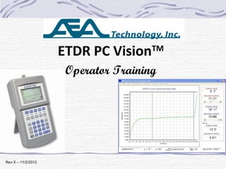
- 1. January 24, 2012 Rev X – 11/2/2012 ETDR PC VisionTM Operator Training
- 2. Table of Contents Training Section Slide(s) Overview 3 Locating and loading ETDR PC Vision 4- 6 Getting Started 7- 8 Initial Communications Setup 9-11 Get Trace tab and Graphic Plot 12-14 Chart’s Expanded Menus 15-22 Chart Zoom 23 Saved Traces tab 24-25 Setups tab 26-27 Cables tab 28-30 Contact Information and Q&A 31-32 2
- 3. ETDR PC Vision Software Operates on: Windows 7® , Windows XP® or Vista® Platforms Upload TDR’s current trace or saved traces to the PC Archive the traces on the PC or other memory media No platform license – Load on any number of PC’s Upload and Download Cable Lists to the E20/20 TDR Upload and Download instrument setups to the E20/20 TDR 3
- 4. Locating ETDR PC Vision ETDR PC Vision folder ETDR PC Vision Software Readme File FTDI Drivers folder Readme File: Version number Updates by version number Helpful loading information Operator Manual: Detailed installation instructions Operating Instructions E20/20 TDR October 29, 2012 ETDR PC VisionTM Operator Manual, Basic Guide, Quick Start Guide, Application Notes, & Training Version 2012.9 4
- 5. Locating ETDR PC Vision In the pull-down menu Click on “Software” ETDR PC Vision Zip File ETDR PC Vision Software Readme File 5 www.aeatechnology.com
- 6. Installing ETDR PC Vision Installation from AEA Technology’s CD: 1. Place the CD in the CD-ROM Drive 2. Use Windows Explorer to locate the ETDR PC Vision folder 3. Double click on the “Setup.exe” file to start the installation 4. Follow the installer’s on screen instructions Installation from a downloaded zip file: 1. Expand the directory contents of the zip file to a folder (Attempting to install from the zip directory will fail) 2. Double click on the “Setup.exe” file to start the installation 3. Follow the installer’s on screen instructions 6
- 7. Getting Started with ETDR PC Vision 1. Turn on the E20/20 TDR and wait for the Measurement Screen to appear (will not communicate if off or in menus). 2. Connect the TDR and PC using the supplied USB Cable 7 3. Double-click the icon on the desktop to open application
- 8. Getting Started with ETDR PC Vision Searching for TDR First attempt to connect will fail. This is normal. See message sequence below. TDR not found 8
- 9. Initial Communications Setup 9 Click on the “COM Port Utilities” tab to set a COM Port/USB link Step 1 – Follow the check list to ensure communications setups are correct Step 2 – Press the “Rescan…” button for the operating system to assign a new COM Port. If a new COM Port does NOT appear skip to the next slide Step 3 – With new COM Port, press the “Connect Port/Poll TDR” button to connect. A good connection will appear.
- 10. Initial Communications Setup 10 If all the check list items are set correctly and “Rescan for Available COM Ports” fails to reveal a port, FTDI Drivers need to be installed. Drivers are located on the enclosed CD and instructions are in the Operator Manual Section 5. FTDI Drivers are also available from: www.ftdichip.com/Drivers/VCP.htm
- 11. Initial Communications Setup With FTDI Drivers installed, repeat first connection steps (slides 8 and 9). After that future connections will be automatic. Note: If the same PC is used to connect to multiple TDRs, use “Rescan for Available Com Ports” to assign a new COM Port to each TDR. 11
- 12. Get Trace Tab 12 Uploads and graphs TDR’s currently displayed trace Opens previously saved trace on the PC or other storage media. Usable without a TDR connected
- 13. Graphic Plot of a Trace Graphic plot with TDR trace, Z Scale (left), Range (bottom) & cursors. Cursors’ data & controls with Delta (differential data) 13 525 ELM-8 DROP
- 14. Graphic Plot of a Trace 14 TDR trace data (not user changeable on PC) 525 ELM-8 DROP Trace title as uploaded Trace title as user modified on PC
- 15. Chart - Expanded Menu Bar View 15 Opens a new chart from PC drive or other storage media Opens a “SaveAs” window to save this chart Export Graphics Export to BMP, JPG, GIF, or TIFF file format.
- 16. 16 Export Data Export to Excel or Word as .csv file: feet = 1920 data pts, Meters = 2000 data pts. Each Data pt = Index #, Distance, & Impedance (Z).Print Graph Only Print Graph and Data Two Print optionsPlot Compare Opens archived trace to overlay with currently displayed trace on the same graph Chart - Expanded Menu Bar View
- 17. 17 Complete chart becomes available on Clipboard to paste into other applications Chart - Expanded Menu Bar View
- 18. 18 Default=“Cursor Values displayed.” Selecting “Maximize Plot” expands the graph over cursor values. Chart - Expanded Menu Bar View
- 19. 19 Save Settings As … Saves chart settings to a file on the PC. Includes: graph’s Range and Impedance scale, background color, size, etc. Load Settings … Recalls saved settings for use with new uploaded traces Chart - Expanded Menu Bar View
- 20. 20 Chart Axes Uncheck to manually adjust graph’s scales, then click “Apply” to return to the chart. Chart - Expanded Menu Bar View
- 21. 21 Opens Title Edit sub-window for making changes. 65 characters fills the top of the chart. Chart - Expanded Menu Bar View
- 22. 22 Trace Colors Select color for: Main Trace, and if selected for: 2nd , Kinks Only, & All Faults traces. Data Points Turns on Data Point markers along trace: Feet=1920 pts Meters=2000 pts Show Data Point Values Works with “Data Points” &“Tool Tip” X=Range Y=Impedance (Z) Tooltip Mouse pointer will reveal data point values Micro Fault Add “Kinks Only” and/or “All Fault” traces to graph Chart - Expanded Menu Bar View
- 23. Chart - Zoom Step 1-Place mouse at upper left corner of desired start, press and hold left click Start Stop Step 2-Drag mouse down & right, and release click at desired stop point Un-Zoom Place the mouse pointer at the lower right corner of the graph, click and hold, drag to upper left corner 23
- 24. 24 Stored Traces Tab Use this tab to: 1. Upload a list of stored traces from the TDR. 2. Plot any selected trace. 3. Copy highlighted traces to Clipboard for pasting/printing/saving list. 4. Archive a highlighted list of traces to save as one file. 5. Delete one trace or a highlighted list of traces from the TDR’s memory.
- 25. Stored Traces Tab 525 ELM-8 DROP 75 85.0 10 OCT 2012 12:23PM 525 ELM-LRM 75 85.0 10 OCT 2012 11:40AM 525 ELM-TEL 100 67.5 10 OCT 2012 10:36AM SPRG-ELM-HL 75 87.0 10 OCT 2012 10:12AM MAIN-SPRG-HL 75 87.0 10 OCT 2012 9:21AM 13ST-4AVE-HL 75 87.0 9 OCT 2012 4:47PM 4AVE-HL2 75 87.0 9 OCT 2012 3:21PM 4AVE-HL 75 87.0 9 OCT 2012 1:54PM 1628-5AVE DROP 75 85.0 5 OCT 2012 5:17PM 1628-5AVE HL 75 87.0 5 OCT 2012 4:01PM Press first to upload a list of TDR’s stored traces Direct save from TDR’s memory to PC folder 25 Deletes selected traces from the TDR’s memory. Caution – There is NO UNDELETE Use to plot a selected trace
- 26. Setup Tab 26 Use this tab to: 1. Read the TDR’s current Setups. 2. Edit the setups. 3. Write setups back to the TDR or to a PC file to save. 4. Read setup files on the PC and download them to the TDR NOTE: “System Time” is PC’s date/time.
- 27. Setup Tab 27 Step 1-Press either button to obtain valid data (gray data text is not valid) Step 2-Enter data or use box’s pull down menu to select change Step 3-Press desired button to download new setup to the TDR or save setup to a file.
- 28. Cables Tab 28 Use the Cables tab to: 1. Read a Cable List from either the TDR or a PC file. 2. Edit the list in the “Selected Cable Values Description” boxes. 3. Write a Cable List to either the TDR or a PC file.Note: Open memory slots are indicated by: “Open nn”= number of remaining slots open. “Open Z=10 & VF=5” (place holder values)
- 29. Cables Tab Read or write Cable List from TDR or from a stored list on the PC Use these keys and “Selected Cable Values” to edit the list Write the Cable List to the TDR or to a Cable List file on the PC 29
- 30. Cables Tab – List Help Four cable lists are loaded on the PC with ETDR PC Vision: CATV – Hard-line, drops, and TIA Cat 2-6A types Telco – 19-22AWG OSP, drops, and TIA Cat 2-6A types Broadcast – Variety of 50 & 52 Ohm coax VDV/RF – Variety of 50-75 Ohm coax & TIA Cat 2-6A types If the “Read Cable List File” button does not automatically open the folder with these cable lists refer to the Operator Manual Section 5 “Default Location for Data Files…” When a list is modified, save a copy on the PC as backup. List files will be assigned the “.cbl” extention to ID them. 30
- 31. Maintenance, Service and Warranty Basic Guide or Operator Manual, Maintenance, Service & Warranty. Warranty – One year against material & workmanship defects Questions, By all means – Contact us: AEA Technology, Inc. 5933 Sea Lion Place, Ste 112 Carlsbad, CA 92010 Tel: 800-258-7805 or +1-760-931-8979 Fax: +1-760-931-8969 www.aeatechnology.com Email Application Notes Operating Manuals TDR PC Vision Data Sheets See “User Troubleshooting Guide” 31 Quick Start Guide
- 32. Questions on ETDR PC Vision software? Windows 7, Vista, Windows XP, Word, and Excel are registered trademarks of Microsoft® Corp. 32