Emerging Hazards: Renewables and Microgrids, U.S. Department of Energy, Energy Systems Integration Facility Case Study

AEI / Affiliated Engineers presents the Energy Systems Integration Facility, a 182,500 square foot building that provides laboratory and research space for 200 scientists and staff working on promising clean energy technologies and testing their interaction with each other and the grid. Specific areas of research include: • Smart grids, power electronics. • Solar: interconnection, parabolic solar concentrators, building integration, and system optimization. • Buildings: sensors and controls, systems integration, modeling, and Zero Energy Building simulation. • Hydrogen: electrical interfaces, electrolyzers, storage, quality standards, fueling systems, fuel cell integration. • Wind: models, generation, and grid interaction, electrical grid analysis. • Vehicles: grid connected plug-in and vehicle-to-grid electrical integration, battery thermal management, and power electronics. • Biofuels: generator sets and engines. • Energy storage: electrical, mechanical, and thermal. • Microturbines. AEI’s work included the design of: • Research Electrical Distribution Bus (REDB): A first-of-its-kind, the REBD is a power integration circuit made up of two AC and two DC ring buses that interconnects testing components across the building’s 15 laboratories. Researchers can test new energy technologies on real and simulated power systems. • Supervisory Control and Data Acquisition (SCADA) System: Integrated throughout the facility, the SCADA monitors and controls the REDB operations and gathers real-time, high-resolution data for collaboration and visualization. The SCADA also monitors SIL-2 (Safety Integrity Level) rated laboratory PLCs providing emergency stop functionality, gas detection, alarming (horns and lights), and other required safety measures. These systems are all interconnected with the fire alarm, building automation system, and local lab equipment to provide a seamless facility response across systems to various conditions.

Recomendados
Recomendados
Más contenido relacionado
La actualidad más candente
La actualidad más candente (20)
Destacado
Destacado (15)
Similar a Emerging Hazards: Renewables and Microgrids, U.S. Department of Energy, Energy Systems Integration Facility Case Study
Similar a Emerging Hazards: Renewables and Microgrids, U.S. Department of Energy, Energy Systems Integration Facility Case Study (20)
Último
Último (20)
Emerging Hazards: Renewables and Microgrids, U.S. Department of Energy, Energy Systems Integration Facility Case Study
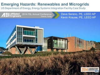
- 1. Emerging Hazards: Renewables and Microgrids US Department of Energy, Energy Systems Integration Facility Case Study Photo by Dennis Schroeder, NREL Dave Sereno, PE, LEED AP Kevin Krause, PE, LEED AP 2014 I2SL Annual Conference Orlando, Florida
- 2. Learning Objectives • Safety as a culture. • Introduction to PHA (Process Hazards Analysis). • Apply PHA to a micro grid/smart grid R & D Lab.
- 3. Presenters Dave Sereno, PE, LEED AP Principal dsereno@aeieng.com Kevin Krause, PE, LEED AP Principal kdkrause@aeieng.com
- 4. Why this topic? 1.Rise of Arc Flash 2.Rise of DC components due to: a. NZB (Net Zero Buildings) b. Data Centers c. Transportation Infrastructure d. Renewables
- 5. Q: Why NREL ESIF as a case study? A: It has it all Photo by Dennis Schroeder, NREL
- 6. DOE NREL South Table Mountain Campus Golden, Colorado
- 7. Team Participants DESIGN CONSTRUCTION SmithGroupJJR Affiliated Engineers, Inc Martin & Martin JE Dunn Construction Company MTech Mechanical Encore Electric, Inc. Courtesy of SmithGroupJJR
- 8. Three Building Components: East Elevation Office Data Center High Bay Laboratories Photo by Dennis Schroeder, NREL
- 9. Three Building Components: West Elevation Photo by Dennis Schroeder, NREL OfficeData Center High Bay Laboratories
- 11. Residential Commercial Utility/Grid/Industrial Three Scales: Residential, Commercial & Industrial/Grid
- 12. ESIF Laboratories High Performance Computing, Data Analysis, and Visualization 16. ESIF Control Room 17. Energy Integration Visualization 18. Secure Data Center 19. High Performance Computing Data Center 20. Insight Center Visualization Fuel Systems Laboratories 9. Energy Systems Fabrication 10. Manufacturing 11. Materials Characterization 12. Electrochemical Characterization 13. Energy Systems Sensor 14. Fuel Cell Development & Test 15. Energy Systems High Pressure Test Thermal Systems Laboratories 6. Thermal Storage Process and Components 7. Thermal Storage Materials 8. Optical Characterization Electrical Systems Laboratories 1. Power Systems Integration 2. Smart Power 3. Energy Storage 4. Electrical Characterization 5. Energy Systems Integration
- 13. Test and Evaluation of all types of distributed generation, storage and interconnection systems Grid Simulator Load Simulators Synchronous Generators PV Array 3ACBuses Utility Grid Battery Banks 3 DC Buses Inverters Fuel Cells Electrolyzer Microturbines Wind Turbines PHEV/V2G ESIF Genesis: DERTF Precursor Facility
- 14. Distributed Energy Research Test Facility (DERTF) Example Projects – Interconnection System Testing Distributed Energy Resources Interconnection Technologies Electric Power Systems Fuel Cell PV Microturbine Wind Generator Inverter Switchgear, Relays, & Controls Functions • Power Conversion • Power Conditioning • Power Quality • Protection • DER and Load Control • Ancillary Services • Communications • Metering Microgrids Energy Storage Loads Local Loads Load Simulators Utility System PHEV - V2G ESIF Genesis: DERTF Precursor Facility
- 15. Learning Objectives • Safety as a culture. • Introduction to PHA (Process Hazards Analysis). • Apply PHA to a micro grid/smart grid R & D Lab.
- 16. Safety as a Culture 1. End Goal: a. Minimize lost man hours during construction b. Increase design phase impact c. Minimize risk for all parties d. Optimize/accelerate AHJ reviews 2. The Safety Minute: a. Benefits beyond safety b. Resources c. Sustaining enthusiasm 3. Differentiate: a. Proactive safety systems b. Reactive safety systems c. And how they relate to PHA and budget
- 17. Safety Programming: Proactive and Reactive
- 18. Hydrogen Storage Pad 45’= 3-Stories 45’ Safety Programming: Proactive and Reactive
- 19. Safety Common Interface: Pier Detail Gas Detection E-Stop BNC Temperature Multi Conductor Configurable: SCADA Interface Configurable: DUT Communication Interface Configurable: Hardwired Control Interface
- 20. Safety Common Interface: Pier Plan
- 21. Safety Common Interface: Portable Carts
- 22. Learning Objectives • Safety as a culture. • Introduction to PHA (Process Hazards Analysis). • Apply PHA to a micro grid/smart grid R & D Lab.
- 23. PHA: Process Hazards Analysis • Most frequently applied to Process Industry, refineries, chemical mfg, drug mfg, etc… • Simple Matrix: Severity and Likelihood • (2) Common Methodologies: • Point to Point , aka P & ID • “What if” • Software PHA tools • Subjectivity removed • Automated documentation
- 24. PHA: Let’s talk risk
- 25. PHA Starting Point: Owners Risk Policy LIKELIHOOD LIKELIHOOD PER YEAR SEVERITY Catastrophic Critical Marginal Negligible $1M $100K - $1M $10K - $100K $10K Death Severe Injury Minor Injury No Injury Frequent >1 High High Moderate Routine Reasonably 1 to 0.1 High High Moderate Routine Occasional 0.1 – 10-2 High Moderate Low Routine Remote 10-2 – 10-4 Moderate Low Low Routine Extremely Remote 10-4 – 10-6 Low Low Routine Routine Impossible <10-6 Routine Routine Routine Routine High Risk Moderate Risk Low Risk Routine Risk
- 26. PHA: Safety Integrity Level (SIL) Metric SIL Availability Probability of Failure on Demand (avg) Mean Time Between Failures 4 >99.99% 10-5 to < 10-4 100000 to 10000 3 99.9% 10-4 to < 10-3 10000 to 1000 2 99-99.9% 10-3 to < 10-2 1000 to 100 1 90-99% 10-2 to < 10-1 100 to 10 High Risk Moderate Risk Low Risk Routine Risk
- 27. Learning Objectives • Safety as a culture. • Introduction to PHA (Process Hazards Analysis). • Apply PHA to a micro grid/smart grid R & D Lab.
- 28. Residential Home Energy Distributed Energy Storage Bulk Energy Storage Advanced Solar Inverters Hydrogen Technologie s Commercial Buildings Wind Energy Hydrogen and Electric Vehicles Microgrids Energy Efficiency Technology ESIF Mission to Enable “Smart Grid” SMART GRID
- 29. Research Electrical Distribution Bus (REDB) AC • Rated 600Vac 3ϕ, 2ϕ, or 1ϕ • 5-wire design: neutral with selectable ground bonding location • 16 Hz to 400 Hz • 250A and 1600A installed • 250A and 2500A planned (future) • Experiment connection via cart CB, bus plug CB or fuse, or direct (main lug only) • Connects PSIL, SPL, ESL, GSE, LBE, LVOTA, MVOTA, ESIL DC • Rated ±500Vdc or 1000Vdc • 4-wire design: positive, negative, common, and ground • Any pole may be tied to ground at selectable location • 250A and 1600A installed • 250A and 2500A planned (future) • Experiment connection via cart contactor/fuse or direct (main lug only) • Connects PSIL, SPL, ESL, PVE, LVOTA, MVOTA, ESIL
- 30. Research Electrical Distribution Bus (REDB)
- 31. REDB: 20,000 Circuit Permutations • Unconstrained: Total # Circuits (all Combinations) 1.33499E+95 !!! • One Constraint: Total # Circuits (all Combinations) 3.96141E+28!! • Three Constraints: Total # Circuits (all Combinations) 1.932E+4! (19,320)
- 32. REDB: One Permutation Example
- 33. Proactive System: Kirk Key LOTO
- 34. REDB Room DC REDB Equipment Room AC REDB Equipment Room House Power Equipment Room
- 35. Proactive System: REDB Access Control
- 36. Everything in Loop Must Meet SIL Level • Instrument Measuring (Unknown SIL rating) • PLC (Easy to find to SIL-3 Ratings) • Relay (Easy to find for SIL-3 Ratings) • Shunt Trip Breaker (Like SIL-2 Rating) • Communications between different vendor systems are not SIL rated. High Risk Moderate Risk Low Risk Routine Risk
- 37. REDB: PHA Conclusion • Multiple layers of defense are needed to get to the statistical frequency required by NREL Safety • Breakers in series, redundancy, (10-2 * 10-2 = 10-4) • PLC/normal instrumentation (10-1) • SOP (10-1) • Total = 10-6 High Risk Moderate Risk Low Risk Routine Risk
- 38. Emerging Hazards: Renewables and Microgrids US Department of Energy, Energy Systems Integration Facility Case Study QUESTIONS 2014 I2SL Annual Conference Orlando, Florida Dave Sereno, PE, LEED AP Kevin Krause, PE, LEED AP Photo by Dennis Schroeder, NREL