Analysis of PVSyst Loss Diagram
•
13 recomendaciones•13,054 vistas

PVSyst is a standard tool for determining the generation from a solar plant, however there is little standardisation over the losses to be assumed. Based on Gensol's experience, every loss has been analysed & through this document we are indicating on the loss percentage to be assumed.

Recomendados
Recomendados
Más contenido relacionado
La actualidad más candente
La actualidad más candente (20)
Destacado
Destacado (20)
Similar a Analysis of PVSyst Loss Diagram
Similar a Analysis of PVSyst Loss Diagram (20)
Más de Gensol Engineering Limited
Más de Gensol Engineering Limited (20)
Último
Último (20)
Analysis of PVSyst Loss Diagram
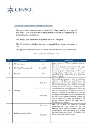
- 1. Generation Assessment and Loss Justification The generation was estimated considering 315Wp modules of a reputed make and 1MW solar inverter of a reputed make as initial design inputs for conducting the simulations. The project uses a seasonal tilt system for with 7.5m pitch. The DC to AC overloading that has been decided as a design parameter is 25%. The typical loss breakdown is as shown below with relevant justifications Table 1: Justification of PVSyst Losses S.No. Parameter Measure Justification 1. PV Syst Version 6.41 Latest version of PVSyst simulation tool has been used 2. Tilt Angle/Tracking Angle 5 o and 30 o For seasonal tilt, the aforementioned tilt angles for summer and winter have been assumed. 3. Pitch(m) 7.5 Considering the overloading of 25%, and corresponding land usage and generation optimization, the pitch values given here came out to be optimal 4. Shading -0.2% (5 o) Near shading is caused by inter row distance and due to tall objects like control rooms and lightening arrestors. For shading from tall objects, sufficient spaces are left by conducting a shadow estimation study so as to keep the PV array shadow free during generation hours. The near shading loss due to inter row spacing is however determined by PVSyst as per the design pitch considered. In the case of seasonal tilt, the shading losses are low for summer tilt and is higher for winter tilt. However, the average shading loss will fall somewhere in between the two values. -3.7% (30 o) 5. Incidence Angle Modifier -2.2% (5 o) IAM loss accounts for losses in radiation penetrating the front glass of the PV modules due to angles of incidence other than perpendicular. The loss figures is a module dependent parameter and is calculated by the PVSyst as per the module chosen. -3.3% (30 o)
- 2. 6. Soiling Loss -1.5% This is the loss due to dust and bird droppings on the PV modules depending on the environmental conditions, rainfall frequency and on the plant’s O&M module cleaning strategy. To assure the maintenance of soiling losses below 1.5%, a novel soilingestimation setup will be setup at plant during O&M consisting of two PV strings. One of the PV strings will be cleaned on a daily basis, while the other one will not be cleaned. Once, the difference between performance of the two strings will start touching 1.25%, a module cleaning cycle of the entire plant will be initiated, thus ensuring soiling loss in line with the design assumption. 7. Module Temperature Loss -9.5% (Seasonal) The characteristics of a PV module are determined at standard temperature conditions of 25˚C. Considering the temperature coefficient of the 315Wp modules selected, the module performance decreases by -0.40% for every oC rise in cell temperature. Module temperature loss is computed by the PVSyst by considering the temperature profile of the location as per the meteo database. Since, the site is located in Rajasthan, a desert region with high temperatures, and the high temperature losses calculated are representative of the high temperature profile. 8. Module Quality Loss +0.4% PV modules generally deviate from the manufacturer’s technical specifications. The 315W modules considered here are supplied with a positive Power tolerance of 0 to 3%. The developer has thus considered a quality gain of 0.4%, although on a conservative side so as to account for other contingencies in generation estimation. 9. First Year Module Degradation (under Light Induced Degradation(LID)) -1.5% The performance of PV modules degrades over the time. The degradation is most significant during few hours of first exposure of PV modules to light. This phenomenon is known as Light Induced Degradation (LID). Factors affecting the degree of degradation include the quality of materials used in manufacture, the manufacturing process and the quality of assembly and packaging of cells into the modules. The first year degradation considering LID and annual degradation is guaranteed to be less than 2.5% in the datasheet. However, as per the general industry experience, the first year degradation for Tier-1 modules has typically been observed between 0.8% to 1.5%. Hence, the first year module performance degradation has been considered as 1.5% here.
- 3. 10. Module Array Mismatch Loss -0.8% Mismatch losses represent the mismatch in current/voltage of modules in a string due to statistical variations. Typically, the mismatch losses are considered as 1%. However, the loss can be reduced by sorting the modules as per current before factory dispatch. The modules supplied at site with a 3-bin current sorting will effectively reduce the mismatch losses. Hence, we have considered the module mismatch losses as 0.8%. 11. DC Ohmic Wiring Loss -1.5% (STC) Electrical resistance in the wires between the power available at the modules and at the terminals of the array gives rise to ohmic losses (I²R). For well-designed plants, DC cabling losses at STC vary from 1.2% to 1.5% at STC. We have considered 1.5% as the DC Ohmic losses at STC. The losses are at full load, and the PVsyst computed the overall losses considering the solar plant operates at partial loads most of the times. The final loss then computed by PVSyst corresponding to 1.5% loss at STC considering the partial load profile of plant is 1.1% 12. Inverter Loss during Operation (Efficiency) -1.7% Inverters convert power from DC into AC at a certain efficiency. This results in a loss of power during conversion from AC to DC. The efficiency curves are inverter dependent. In our case, the inverters considered are 1000kW of a reputed make. The efficiency loss has been calculated by the PVSyst as per the manufacturer provided efficiency curves of the inverter and stands at around 1.7%. 13. Auxiliary Losses -0.6% Various components of plants like inverters, PLC, module cleaning system, plant lighting, security systems etc and amenities like Air conditioning, plumbing and others consume electricity for their operation. This is known as auxiliary loss. The auxiliary losses vary from 0.5% to 1% depending upon the size, design and structure of the plant. Typically, small plants require a higher percentage of auxiliary consumption than bigger plants on relative terms. Various measures such as night disconnect, self-powered trackers, LED lighting, have been considered in the design for reducing auxiliary consumption. The auxiliary losses have thus been reasonably considered at 0.6% with sufficient margin.
- 4. 14. AC Ohmic Losses -0.5% (Full Load) This includes ohmic losses in the cable from inverter leading to the substation, and depends on the sizingof cables during the design. During the design of the plants, the AC cable sizing has been done in such a way that the losses do not exceed 0.5% in the AC side. Full load AC ohmic losses of 0.5% have been considered, corresponding to which PVsyst computes the overall losses considering the solar plant operates at partial loads most of the times. The final loss then computed by PVSyst corresponding to 0.5% loss at STC considering the partial load profile of plant is 0.3%. 15. System Unavailability -0.5% Downtime depends on the diagnostic response time and stock of spare equipment. Further, loss in generation due to unavailability of plant and grid are also accounted for in downtime losses. Typically, the unavailability is higher for smaller plants, as compared to larger plants due to relative impact of failure of a single component on the entire plant availability. The O&M scheme thought out also considers stocking of inverter transformer, breaker, inverter IGBT stacks, and modules, cables of all sizes, consumables and on site deployment of service persons of critical components like transformers, inverters on site along with regular manufacturer training of O&M personnel. Large solar plants in solar parks are now connected at 132kV to the grid which is ultimately connected at 400kV to green corridor grid network, which will be extremely stable with very less downtime. Considering the above, the system unavailability has been considered as 0.5% 16. External Transformer Loss -1.6% Large losses may rise in the transformer but are generally less than 1% for each transformation level. Given the fact that the plant will be evacuating at 132kV, two levels of losses have been considered; 1.0% for the intermediate transformation at 33/11kV, and 0.6% (following the GTP of the transformer to be used on-site) for the second level of transformation at 132kV in line with standard design practices.