Шестеренные насосы серии Т Steimel
•
0 recomendaciones•218 vistas

Шестеренные насосы серии Т Steimel

Recomendados
Recomendados
Más contenido relacionado
La actualidad más candente
La actualidad más candente (15)
Similar a Шестеренные насосы серии Т Steimel
Similar a Шестеренные насосы серии Т Steimel (12)
Más de Arve
Más de Arve (20)
Último
Último (20)
Шестеренные насосы серии Т Steimel
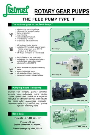
- 1. ROTARY GEAR PUMPS THE FEED PUMP TypE T type T • pulsation-free pumping delivery • independent of sense of rotation • sturdy construction • easy mounting • wide selection of materials • several sealing variants • for packings with suction bore type TM • fully enclosed heater jackets • heatable with thermal oil, water or steam ◦ heating temperature up to 320 °C ◦ pressure up to 8 bar max. • DIN flange connection or screw thread type TE TFE • electric heating of end cover plate • heatable via four cartridge-type heaters controlled by a system thermostat adjustable from 0 to 300 °C type TA TMA • pumps abrasive and pigment-containing media • gearing outside the pump • fully sealed anti-friction bearings • highly wear-resistant rotary shaft seal The various types of the Feed Pump T Feed Pump T Feed Pump TM Feed Pump TFE Feed Pump TA Bitumen • tar • binders • paints • varnishes solvents • glues • adhesives • resins • plastics polyols • plasticizers • waste oil • engine oil heavyfueloil•lubricationoil•waxandfoodstuffs fats • cacao butter • cacao mass • chocolate • molasses • waffle dough and fruit pulp • glucose syrups • and many more Pumping media (selection) Flow rate 15 - 1,500 cm³ / rev Pressure 16 bar (higher pressures on request) Viscosity range up to 80,000 cP Basic data
- 2. Range of applications 2 Basic features With the series type T we offer a program with several variants and constructions for the transport of almost all pumpable media. It can be used up to maximum rotational speeds of 1500 rpm at pressures up to 16 bar. The rotational speed is basically determined by the viscosity or lubricity of the pumped medium. At viscosities in excess of 10000 mm²/s the medium to be pumped should flow to the pump. In case of suction heights of more than 7 m LC and admission pressures in excess of 2 bar please contact our engineering depart- ment as larger piping cross sections will be required! The pumps are driven by electric motors, backgeared motors, belt drives adjustable gear motors, or similar. All pumps can operate with clockwise or counter-clo- ckwise sense of rotation. Please indicate the required sense of rotation in your purchase order. Slight peaks may be produced in all pumps with drive shaft positioned below. Here it must be taken into account that the direc- tion of delivery flow will change. Nearly all construction types and sizes of pumps can be provided with a built-in, adjustable pressure relief val- ve. We also offer separate pressure relief valves to be inserted into the pipeline! Materials Grey cast iron Pump body parts: Shafts, gearwheels: Bearings: Stuffing box packing: grey cast iron (EN-GJL-250/GG 25, GGG 40, GS 45) case hardened steel (16 Mn Cr S5) special-type bronze AW Buramex SF free of silicone Zinc-free bronze Pump body parts: Shafts, gearwheels: Bearings: Stuffing box packing: zinc-free cast bronze (G-Cu-Sn10 / GBz10) stainless steel (1.4462) zinc-free Bronze (CuSn 10 / GBz 10) Buramex SF free of silicone Stainless steel Pump body parts: Shafts, gearwheels: Bearings and wearings disks: Stuffing box packing: stainless steel (1.4581) stainless steel (1.4462) artificial carbon, Ceramic, Bronze Buramex SF free of silicone Other materials, seals or special designs upon request. General engineering, construction, coating machine manufacturers, bitumen processing, chemical industry, paint industry, printing ink industry, foil manufacture, foodstuff such as chocolate production and other, food processing, cardboard and plastic processing machines, paper manufacturers, chipboard production and the au- tomotive industry amongst many other industries. Codes of designs Designs T standard model TF casing with DIN (ANSI) flange connections S support bearing for belt drive A external antifriction bearing Z external gears E electrical heating M heating jacket DG pressure relief valve in casing DD pressure relief valve in cover DDM pressure relief valve with heating jacket GKM bedplate, coupling, motor GKGM bedplate, coupling, gear motor Shaft sealing P stuffing box packing G mechanical seal (GLRD) GP mechanical seal with secondary safety stuffing box packing GGK double mechanical seal (back-to-back) with quench or buffer fluid Order example T Type (design) 10 size 240 size, gear width (mm) G with mechanical shaft seal DD with pressure relief valve in cover GKM bedplate, coupling, motor T 10-240/GDD-GKM Application in ATEX range We supply gear pumps according to EC-directive 94/9/EC (ATEX 95). Equipments for zone 1 + 2 (II2G / D T3 und T4), which ensure a high level of safety. Designed for the case, it is to be counted on an explosive atmosphere. Shaft seal- ing (G + GGK) with temperature monitoring. Equipments for zone 2 + 22 (II3G / D T3), which en- sure a normal level of safety. Designed for the case, it is to be counted on an explosive atmosphere rather rarely and if so, only for a short time. Shaft sealing (P + G) without temperature monitoring.
- 3. 3 Pump capacities Pump size Pump capacity Pressure p (bar) at rotational speed n = 500 1/min Pressure p (bar) at rotational speed n = 700 1/min Pressure p (bar) at rotational speed n = 950 1/min Pump capacity cm³/rRated power 2 4 6 8 10 2 4 6 8 10 2 4 6 8 10 T 0-36 Motor 1 l/min 7,0 6,7 6,5 6,2 6,0 10,0 9,5 9,0 8,5 8,0 13,5 13,0 12,5 12,0 11,5 15NkW 0,12 0,15 0,18 0,21 0,24 0,13 0,17 0,21 0,25 0,29 0,14 0,16 0,23 0,28 0,33 kW 0,25 0,25 0,25 0,37 0,37 0,25 0,25 0,37 0,37 0,37 0,25 0,25 0,37 0,37 0,55 T 1-60 Motor 1 l/min 12,5 11,5 11,0 10,5 10,0 16,5 16,0 15,5 15,0 14,5 23,0 22,0 21,0 20,0 19,0 25NkW 0,15 0,19 0,24 0,29 0,33 0,15 0,20 0,27 0,33 0,39 0,25 0,33 0,40 0,48 0,55 kW 0,25 0,25 0,37 0,37 0,55 0,25 0,37 0,37 0,55 0,55 0,37 0,55 0,55 0,75 0,75 T 2-70 Motor 1 l/min 19,0 18,5 18,0 17,5 17,0 26,5 26,0 25,5 25,0 24,5 36,0 35,0 34,0 33,0 32,0 40NkW 0,21 0,26 0,32 0,37 0,42 0,25 0,33 0,40 0,48 0,55 0,30 0,42 0,55 0,68 0,80 kW 0,37 0,37 0,55 0,55 0,55 0,37 0,55 0,55 0,75 0,75 0,55 0,55 0,75 1,1 1,1 T 3-80 Motor 1 l/min 29 28 27 26 25 40 39 38 37 35 55 54 53 52 51 60NkW 0,26 0,36 0,44 0,53 0,63 0,40 0,55 0,70 0,85 1,0 0,6 0,8 1,0 1,2 1,4 kW 0,37 0,55 0,55 0,75 0,75 0,55 0,75 1,1 1,1 1,5 0,75 1,1 1,5 1,5 2,2 T 4-95 Motor 1 l/min 52 51 50 49 48 72,5 71,5 70,0 68,5 67,0 98 97 95 93 91 108NkW 0,60 0,77 0,95 1,12 1,29 0,70 1,00 1,30 1,60 1,80 0,80 1,20 1,50 1,90 2,30 kW 0,75 1,1 1,5 1,5 2,2 1,1 1,5 2,2 2,2 3 1,1 1,5 2,2 3 3 T 6-80 Motor 1 l/min 66 65 64 63 62 92,5 91,0 89,5 88,0 86,5 126 124 122 120 118 135NkW 0,8 1,0 1,2 1,4 1,6 0,9 1,2 1,5 1,8 2,2 1,2 1,7 2,1 2,7 3,1 kW 1,1 1,5 1,5 2,2 2,2 1,1 1,5 2,2 3 3 1,5 2,2 3 4 4 T 6-110 Motor 1 l/min 90 89 88 87 86 126 124,5 123 121,5 120 171 169 167 165 163 182NkW 1,0 1,3 1,6 1,9 2,2 1,2 1,7 2,1 2,7 3,1 1,5 2,1 2,8 3,5 4,1 kW 1,5 2,2 2,2 3 3 1,5 2,2 3 4 4 2,2 3 4 5,5 5,5 T 8-100 Motor 1 l/min 123 122 121 120 119 172 171 170 169 167 234 223 230 228 226 250NkW 1,15 1,5 2,0 2,4 2,8 1,5 2,1 2,8 3,5 4,1 2,2 3,1 4,0 4,9 5,8 kW 1,5 2,2 3 3 4 2,2 3 4 5,5 5,5 3 4 5,5 7,5 7,5 T 8-140 Motor 1 l/min 180 178 176 173 170 252 249 246 242 238 342 338 334 329 323 364NkW 1,6 2,2 2,8 3,4 4,0 2,3 3,2 4,1 5,0 6,1 3,2 4,5 5,8 7,1 8,4 kW 2,2 3 4 5,5 5,5 3 4 5,5 7,5 7,5 5,5 7,5 7,5 11 11 T 10-120 Motor 1 l/min 246 242 239 234 230 344 339 334 328 322 466 460 453 445 437 500NkW 2,3 3,2 4,1 5,0 6,1 3,2 4,5 5,3 7,1 8,4 4,4 6,2 8,0 9,8 11,6 kW 3 4 5,5 7,5 7,5 5,5 7,5 7,5 11 11 7,5 11 11 15 15 T 10-240 Motor 1 l/min 496 490 483 476 468 694 686 676 666 655 942 931 917 904 889 1.000NkW 4,6 6,5 8,3 10,3 12,2 6,4 9,1 11,6 14,4 17,0 8,7 12,3 15,7 19,5 23,1 kW 5,5 7,5 11 15 15 7,5 11 15 18,5 22 11 15 22 30 30 T 11-240 Motor 1 l/min 745 735 725 715 705 1.043 1.029 1.015 1.001 987 1.415 1.396 1.377 1.356 1.340 1.500NkW 7,0 9,7 12,5 15,5 18,4 9,7 13,6 17,4 21,6 25,7 13,0 18,4 23,6 29,3 34,7 kW 11 15 15 18,5 22 15 18,5 22 30 30 18,5 22 30 37 45 NkW = nominal power requirement at the pump shaft related to a viscosity of 50 to 150 mm²/sec (cSt). Subject to change. The pump capacity (l/min) is related to 500, 700 and 950 1/min. It will be reduced as a function of the rated speed of the motor. Variation of the delivery output: ±5%. The pump capacity will also be reduced at a viscosity of less than 50 mm²/sec.. 1 Driving power required (20% additional extra are included). Details in sectional view Design T with stuffing box packing P Pressure relief valve DD (build in counter-cover) Shaft sealing G Shaft sealing GP (typ. application: bitumen processing) Shaft sealing GGK with quench vessel Abbreviations see page 2, codes of designs.
- 4. Gebr. Steimel GmbH & Co. Pumps and centrifuges P.O.Box 1565 Johann-Steimel-Platz 1 Phone: +49 (0) 2242 8809 -0 53762 Hennef 53773 Hennef Fax: +49 (0) 2242 8809 -160 Deutschland • Germany • Allemagne • Alemania http://www.steimel.com • vtp@steimel.com Examples of models T.2-12-2007-en • ©2007Gebr.SteimelGmbH&Co.,Hennef • Modificationsreserved. 4 For the food processing For the paint and printing ink industry For the bitumen processing For the chocolate production T in zinc-free bronze e.g. for leaven filling Pump aggregate T, standard design Pump aggregate T, ATEX design with quench vessel e.g. in printing-ink installation Pump unit with shell-heatable pump body and valve with baseplate, coupling and geared motor for as- phalt-mixing installations e.g. Pump station, complete with thermal- oil circulation pump and piping for asphalt-mixing installations e.g. as Stand-by-pump at an chocolate tank Gear pump TM (up to 1800 cm³/revolution) for chocolate and cocoa mass T in stainless steel