
Recomendados
Más contenido relacionado
La actualidad más candente
La actualidad más candente (20)
Similar a Non linear applications of op amp
Similar a Non linear applications of op amp (20)
Último
Último (20)
Non linear applications of op amp
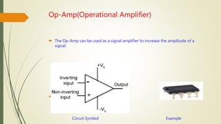
- 1. Op-Amp(Operational Amplifier) The Op-Amp can be used as a signal amplifier to increase the amplitude of a signal. dfg Circuit Symbol Example
- 2. Differentiator A differentiator is an electronic circuit that produces an output equal to the first derivative of its input. In the circuit the non inverting input terminal of the Op-Amp is Connected to ground. That means zero volts is applied to its non -inverting input terminal. If non inverting input terminal zero volts then inverting terminal also be zero volts. Here, Input voltage = Vi output voltage=Vo Circuit of Differentiator Vo = - RCdVi The output voltage Vo is having a negative dt sign which indicates that there exists a 180 ֯ phase difference between the input and the output.
- 4. Integrator An integrator is an electronic circuit that produces an output that is the integrations of the applied input. In the circuit the non inverting input terminal of the Op-Amp is Connected to ground. That means zero volts is applied to its non -inverting input terminal. If non inverting input terminal zero volts then inverting terminal also be zero volts. Here, Input voltage = Vi output voltage=Vo Circuit of Integrator V0=− 1 ∫Vidt Rc The output voltage Vo is having a negative sign which indicate that there exists 180 ֯ phase difference between the input and the output.
- 5. Applications of Op-amp Differentiator and integrator. Differentiating amplifiers are most commonly designed to operate on triangular and rectangular signals. Differentiators also find application as wave shaping circuits, to detect high frequency components in the input signal. The integrator circuit is mostly used in analog computer, analog-to-digital converters and wave- shaping circuits.
- 6. Clippers A clipper is an electronic circuit that produces an output by removing part of the input above or below a reference. The output of a clippers will be same as that of the input for other than the clipper part. There are two type of clippers. (i) Positive clippers (ii) Negative clippers
- 7. Positive clipper A positive clipper is a clipper that clips only the positive portion of the input signal. In the circuit voltage signal Vi is applied to the non – Inverting terminal of the Op-Amp. The value of the reference voltage Vref can be chosen by varying the Resistor. Input voltage = Vi Reference voltage = Vref Output Voltage = Vo (i) If Vi < Vref the diode D1 behave forward bias . So Vo = Vi Circuit of positive clipper (ii) If Vi > Vref the diode D1 behave reverse bias. So Vo = Vref
- 8. Negative clipper A negative clipper is a clipper that clips only the negative protion of the input signal. In the circuit voltage signal Vi is applied to the non – Inverting terminal of the Op-Amp. The value of the reference voltage Vref can be chosen by varying the Resistor. Input voltage = Vi Reference voltage = Vref Output Voltage = Vo (i) If Vi > Vref the diode D1 conduct . So Vo = Vi (ii) If Vi < Vref the diode D1 off. So Vo = Vref Circuit of negative clipper
- 9. Clampers A clamper is an electronic circuit that produces an output, which is similar to the input but with a shift in the DC level. There are two types clamper. (i) Positive clamper (ii) Negative clamper
- 10. Positive clampers A positive clamper is a clamper circuit that produces an output in such a way that the input signal gets shifted vertically by a positive DC value. In the circuit, The AC voltage signal is applied to the inverting terminal of the op-amp. The DC reference voltage Vref is applied to the no inverting Terminal of the op-amp. The value of reference voltage Vref can Be chosen by varying the resistor R2 In this case, we will are Vref of a positive value. circuit a positive clampers
- 11. Negative clampers A negative clamper is a clamper circuit that produces an output in such a way that the input signal gets shifted vertically by a negative DC value. In the circuit, The AC voltage signal is applied to the inverting terminal of the op-amp. The DC reference voltage Vref is applied to the no inverting Terminal of the op-amp. The value of reference voltage Vref can Be chosen by varying the resistor R2 In this case, we will are Vref of a negative value. Circuit of negative clampers
- 12. Waveform of positive clamper and Negative clamper The clamper circuit produce an output in The circuit produce an output in such a way that such away that the voltage signal Vi gets the voltage signal Vi gets shifted vertically shifted vertically upward by the value of downwards by the value of Vref. Vref.
- 13. THANK YOU