Avnet, TE Antenna Selector Guide
•
1 recomendación•679 vistas

Many common electronic devices rely on antennas to communicate wirelessly. Antennas are transducers that convert electromagnetic waves to electric current or vice versa. Antennas can be used in outer space, underwater, rock, or soil. Most common applications use air as the typical propagation medium. While it takes many years to become an expert antenna designer, several basic antenna specifications are described to enable a starting point for antenna selection. Standard antenna solutions are also presented for several common applications.

Recomendados
Recomendados
Más contenido relacionado
La actualidad más candente
La actualidad más candente (19)
Destacado
Destacado (20)
Similar a Avnet, TE Antenna Selector Guide
Similar a Avnet, TE Antenna Selector Guide (20)
Más de Avnet Electronics Marketing
Más de Avnet Electronics Marketing (18)
Último
Último (20)
Avnet, TE Antenna Selector Guide
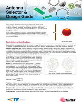
- 1. Antenna Selector & Design Guide Many common electronic devices rely on antennas to communicate wirelessly. Antennas are transducers that convert electromagnetic waves to electric current or vice versa. Antennas can be used in outer space, underwater, rock, or soil. Most common applications use air as the typical propagation medium. While it takes many years to become an expert antenna designer, several basic antenna specifications are described to enable a starting point for antenna selection. Standard antenna solutions are also presented for several common applications. Basic Antenna Specifications The ideal dipole radiator Bandwidth (Frequency band): Bandwidth refers to the range of frequencies over which the antenna is effective. The bandwidth can be centered at one resonant frequency or, more commonly, many resonant frequencies which gives wider bandwidth antennas. Radiation pattern and gain: The ideal antenna is an isotropic radiator, radiating equally in all directions. Antenna performance is usually specified relative to the ideal isotropic antenna. An antenna’s 3-dimensional radiation pattern is typically graphed in separate vertical and horizontal plots to show the relative field strength against a single variable angle. The antenna’s directivity and sidelobes can be visually determined by the polar coordinate plots. The antenna peak gain is the maximum point of field strength around of the polar plot and is indicated in the datasheet in dBi; dB relative to an isotropic radiator. Return Loss: Power not radiated by the antenna is reflected back to the network. The ratio of the reflected signal relative to the input signal is called return loss and is a measure of how well matched the antenna is to the network. Minimal return loss across the desirable frequency band maximizes radiated power. VSWR: The Voltage Standing Wave Ratio (VSWR) is a unit-less measure of the maximum voltage to the minimum voltage of a standing wave in the transmission line. Standing waves result from the mismatched complex impedances between the antenna and transmission line, causing reflections that sum with the input signal. An ideal VSWR is 1.0:1. A VSWR of 2.5:1 corresponds to a Elevation Plane Azimuth Plane return loss of -7.4 dB. VSWR is usually specified worst case but will vary by frequency, so it is helpful to have VSWR characterized Nearly isotropic embedded antenna radiation patterns. across the entire band of interest. VSWR can be converted to return loss as follows: Return Loss = 20 log ( VSWR – 1 VSWR + 1 ) Feed Point: The feed point is where the electric current enters or leaves the antenna. A balanced feed point has two conductors, with equal currents in opposite directions. An unbalanced feed point has just one conductor and a ground. Baluns are used to convert balanced impedances to unbalanced impedances (or vice versa). They can also provide impedance transformation. Polarization: This term refers to the orientation of the electric field of the radio wave with respect to the Earth’s surface. Polarization is determined by the physical structure of the antenna and by its orientation. Power Handling: Embedded antennas may have limited power handling capability, usually specified in the datasheet.
- 2. te connectivity embedded Antennas ease Selection Process In an effort to shorten the antenna design and selection process, TE connectivity has developed a complete family of standard antennas targeted at many of today’s common applications. The ability to embed a TE antenna inside the device without loss of performance is the most important feature. This, coupled with the small size and light weight, provides the designer with a low cost, attractive alternative to the conventional whip antenna. These antennas can mount via standard surface mount process or via through-hole tabs. te Antenna Selector Guide Part Number 1513156-1 1513164-1 1513168-1 1513169-1 1513247-1 1513259-1 1513273-1 1513317-1 1513349-1 38.10 x 38.1 x 38.1 x 38.1 x 37.59 x 35.56 x 49.90 x 18.03 x DimeNsioNs 16.09 x 6.05 6.6 x 1.57 15.24 x 1.57 15.24 x 1.57 15.24 x 1.57 11.94 x 1.57 17.65 x 1.57 20.27 x 1.58 3.76 x 1.57 Peak GaiN +1 dBi +4 dBi 0 dBi +2 dBi 0 dBi, +3 dBi +1 dBi +2 dBi +3 dBi 0 dBi VsWr < 2.5:1 < 2.5:1 < 2.0:1 < 2.5:1 < 3.0:1 < 3.0:1 < 3.0:1 < 3.0:1 < 2.0:1 mouNtiNG SMT SMT Puck Tab Tab Tab SMT Tab Tab SMT baNDs Single Band Dual Band Single Band Single Band Dual Band Quad Band Quad Band 5-Band Single Band FrequeNcy usaGe reGioN 1513156-1 1513164-1 1513168-1 1513169-1 1513247-1 1513259-1 1513273-1 1513317-1 1513349-1 baND (mHz) 824 - 894 GSM / CDMA 850 Americas x x x x x 880 - 960 GSM 900 EU x x x 868 - 870 ISM / ZigBee EU x 902 - 928 ISM / ZigBee US x x 1565 - 1585 GPS Global 1710 - 1880 GSM 1800 EU x x x 1850 - 1990 GSM / CDMA 1900 Americas x x x x 1920 - 2170 UMTS Global x Global 2300 - 3800 WiMAX by Band 2400 - 2483.5 Bluetooth / WLAN / ZigBee / Wi-Fi Global x x 3100 - 6000 UWB Americas Global by 5150 - 5875 WLAN / Wi-Fi x Channel customized Solutions - Molded interconnect Devices (MiD) two Shot molding is a mature and well understood process that remains viable for cost effective and repeatable production of MIds. The basic process has only two steps, injection molding of two distinct thermoplastic polymers and the electroless plating process, resulting in a selectively plated component. In order to achieve the selectivity during plating, a catalyst doped “plateable” resin is molded in conjunction with a standard non-plateable resin to define the desired area to be plated. This area is metallized initially with copper, followed by nickel and, optionally, gold plating. The following are just a few of the several advantages that MId 2-Shot technology delivers compared to alternative technologies: » design flexibility for complex 3-d geometries » Ability to integrate multiple functions into one component » Tightest tolerance for pattern registration to carrier » Fewest manufacturing steps and processes 2 AntennA SeLectoR AnD DeSiGn GuiDe © 2011 AVnET, Inc. All RIghTS RESERVEd.
- 3. It is important to note that most of these embedded antennas have been optimized to operate in conjunction with a minimum specified groundplane or counterpoise length. Please refer to the individual datasheets for minimum groundplane requirements for optimum performance. 1 1513353-1 1513381-1 1513430-1 1513431-1 1513434-1 1513472-5 1513504-1 1513634-1 1513797-1 2118016-1 2118059-1 2118060-1 14.96 x 29.0 x 12.85 x 12.85 x 38.1 x 29.0 x 8.45 x 18.9 x 36.85 x 41.24 x 16.0 x 6.05 16.0 x 6.05 7 12.70 x 0.79 12.0 x 10.0 3.76 x 0.79 3.76 x 0.79 15.2 x 1.57 12.0 x 10.0 6.4 x 0.79 6.2 x 0.79 30.60 x 0.304 29.60 x 0.304 +2 dBi +4 dBi 0 dBi 0 dBi 0 dBi, +1 dBi +3 dBi +2 dBi 0 dBi +1 dBi +2 dBi +4 dBi +2 dBi < 2.0:1 < 3.0:1 < 2.0:1 < 2.0:1 < 2.5:1 < 3.0:1 < 2.5:1 < 3.0:1 < 2.5:1 < 3.0:1 < 3.0:1 < 3.0:1 Universal Universal Flex PCB w/ Flex PCB w/ Tab Antenna SMT SMT Tab Antenna SMT Puck SMT Puck SMT SMT U.FL U.FL Module Module d Single Band Single Band Single Band Single Band Dual Band Dual Band Single Band Single Band Single Band Dual Band Single Band Dual Band 1 1513353-1 1513381-1 1513430-1 1513431-1 1513434-1 1513472-5 1513504-1 1513634-1 1513797-1 2118016-1 2118059-1 2118060-1 x x x x x x x x x x x x x x x x x x Laser Direct Structuring (LDS) is an exciting technology used to create Molded Interconnect devices (MId). Through the use of the dedicated laser system and a variety of resins, it opens up many possibilities to create 3-dimensional MIds with finer line width and spacing than what is possible with the conventional MId processes. The ldS is a three step process. First, the antenna is molded in a standard single shot mold using one of the ldS resins. Second, the desired pattern is directly structured onto the antenna by the 3-d laser system. Finally, the pattern is plated using the industry-standard methods where the plating adheres only where the plastic that has been activated by the laser, thus creating a conductive pattern. ldS offers the same advantages as the 2-Shot technology mentioned above plus the following additional advantages: » Ability to produce thin (0.15 mm) traces » Flexibility for pattern changes during production » Simple/fastest/lowest cost tooling © 2011 AVnET, Inc. All RIghTS RESERVEd. AntennA SeLectoR AnD DeSiGn GuiDe 3
- 4. avnEt ELEctronics MarkEtinG rF & Wireless Design solutions Branch Locations UnitED statEs Atlanta 770-623-4400 From design to volume production, Avnet electronics Marketing offers Austin 512-219-3700 products, services and tools that accelerate customer success. As technology Baltimore 410-423-8800 standards evolve and new RF design solutions emerge, electronic original equipment Boston 978-532-9700 manufacturers (EOEMs) and electronic manufacturing services (EMS) providers must Chicago 847-797-7300 remain compliant with the latest standards while also selecting products that allow for Clearwater 727-507-5000 maximum design flexibility without compromising performance or reliability. Cleveland 440-349-7600 Columbus 614-865-1400 When integrating RF and wireless technologies into an application, developers have Connecticut 203-284-5700 many design options from which to choose. Avnet’s RF design experts act as technical Dallas 214-553-4300 solution consultants, rather than business development or sales managers, by offering the Denver 303-790-1662 engineering community differentiated products and services that accelerate design cycles, Detroit 734-416-5800 augment constrained resources and meet cost and functionalityrequirements. Houston 281-243-7330 Huntsville 256-837-8700 Avnet’s wide selection of products and services is complemented by systems-oriented RF Indianapolis 317-575-3500 Field Application Engineers (FAEs). Avnet RF FAEs give customers of all sizes, regardless of Irvine 949-789-4100 production volume requirements, access to best-in-class wireless products and first-class Kansas City 913-663-7900 engineering support, helping to achieve faster time-to-prototype, market and revenue. Long Island 631-582-7700 Los Angeles 818-594-8200 Avnet RF FAe Profile Milwaukee 262-513-1500 Minneapolis 952-346-3000 » Participates in annual factory training programs North Jersey 973-515-1641 » Averages 16 years of design experience Orlando 407-657-3300 » holds an electrical engineering degree Phoenix 480-643-5600 » has knowledge of new product roadmaps, reference designs and development tools Pittsburgh 724-934-6700 » has embedded wireless design expertise Portland 503-526-6200 Raleigh 919-859-9159 » Supports the needs of customers in local markets Rio Grande 956-631-1610 » Provides insight into technologies, end applications and vertical market segments Rochester 585-350-2800 Sacramento 916-632-4500 Salt Lake City 801-365-3800 Avnet specializes in crafting complete RF and wireless solutions that leverage discrete San Diego 858-385-7500 and/or modular technologies from industry-leading manufacturers and supporting these San Jose 408-435-3500 solutions with associated design-chain and supply-chain services. Seattle 425-882-7000 South Jersey 856-222-6400 Discrete RF & Wireless Products St. Louis 314-770-6300 » Adapters » Phase-locked loops canaDa » Antennas » Power Amplifiers (PA) Montreal 514-335-1000 » » Ottawa 613-226-1700 Attenuators PIn diodes Toronto 905-812-4400 » connectors » Power dividers Vancouver 604-444-3810 » couplers, RF crossovers » Receivers Calgary 403-291-5510 » delay lines » RF/IF Integrated Systems » duplexers » MEXico SAW Resonators » Filters » Guadalajara 5233-3134-2300 Schottky diodes Jalisco 656-640-3230 » Frequency Multipliers » Switches » lnAs » Synthesizers arGEntina » Mixers » Transceivers Buenos Aires 54-11-5199-8300 x308 » MMIcs » Transistors BraZiL » Modulators » Transmitters Avnet do Brasil 55-11-5079-2150 » Oscillators coLoMBia Bogota 57-1-256-7766 RF Modules PUErto rico » 802.11(Wi-Fi) » gSM/gPRS/cdMA Puerto Rico 787-706-1888 » Bluetooth » WiMAX » gPS » ZigBee Avnet RF & Wireless Design Solutions RF & Wireless Information at Your Fingertips @ www.em.avnet.com/rf copyright © 2011 Avnet, Inc. AVnET and the AV logo are registered trademarks of Avnet, Inc. TE (logo) and TE 1-800-332-8638 connectivity are trademarks. All other brands are the property of their respective owners. AEM-TE-AnTEnnA/03_11 em.avnet.com