
Recomendados
Más contenido relacionado
Destacado
Destacado (13)
Similar a FinalChairpaper
Similar a FinalChairpaper (20)
FinalChairpaper
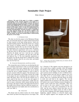
- 1. Sustainable Chair Project Blake Johnson Abstract— The goal of this paper is to obtain a complete understanding of the concepts required in the design of a sustainable chair out of a weak and flimsy material. The general concept and thinking behind the project, as well as the analysis of the reason behind the success of the project is the essential purpose of this project. Statics was the main mathematical base to the entirety of the project, as well as a small knowledge of materials and deformation. The idea of tension vs compression was made apparent during class and directly applied to the design. The ability to realize how each part was going to react with one another was the most essential ability to obtain during the process of the design. I. INTRODUCTION The chair was the first project in the Mechanical Design class. It involved the design of a single material and involved no other material in the entire design process: which also excluded mending material. The design chosen was a design that focused on limiting material by using the smallest measurements required; this was due to the fact that one of the requirements was to keep the design under 500 grams. The chair dimension requirements were to use a minimum of 360 mm wide, by 360 mm deap, by 480 mm high chair. Therefore the design used was a seat that was a perfect circle with a 360 mm diameter, and legs that stood 480 mm high.(see Fig. 3). The most important requirement in the project was that the design had to withstand the weight of Professor Spenko when he sat on the chair, and leaned back into the back rest. II. CONCEPT GENERATION AND EVALUATION The concept that came to fruition was one that kept the seat at it’s minimum requirement in order to avoid large bending moments, which were easily acquired due to the weakness of the material at hand. On top of this there was an attempt to keep the seat at a height minimum as well in order to prevent a moment within the supports. The demensions were not the only requirement in the design, because the weight of the design was also something that was required to stay under 500 grams. Due to the fact that the material was so weak, much of the focus was on the base and support of the chair. With these known requirements, a pugh chart was used in order to determine which original drawing had the best design. The largest weight of this pugh chart focused on the weight of the structure, and how stable the structure was. Then the dimensions were lightly taken into consideration as well. (see Table 1) III. ANALYSIS The design used was almost exactly one of the original ideas drawn up before the design process even began. (See Fig. 1. Picture taken of the fully assembled chair, just moments after the chair successfully withstood the test. fig. 2, Drawing 3) The supports used were designed to cut out as much excess weight as possible, while still keeping the integrity of the supports intact. This was done to allow the stress lines of the design to flow through the supports and to prevent massive buildups of stress in different areas. The original design used only had two supports cross over each other, but as we moved further along in the design process, there was a realization that that design was going to easily twist and bend in the supports. This was the biggest problem that was present in the entire project. With the material used, massive bending moments throughout the support system would have been catastrophic. There was also an issue in the stress analysis of the structure. (see fig. 3) There was a large stress concentration in the seat itself. And the stress analysis showed that there was not enough material in the support system. In order to detour the seat from collapsing and large bending moments from happening, supports running at a forty-five degree angle from the original supports were designed and used. The
- 2. Drawing 1 Drawing 2 Drawing 3 Fig. 2. Three original drawings chosen for the project. TABLE I PUGH CHART Criteria Wt Dwg 1 Dwg 2 Dwg 3 Mass 3 +1 +1 -1 Height 1 +1 -1 0 Seat depth 1 +1 -1 +1 Seat Height 1 +1 -1 +1 Stability 3 +1 -1 +1 Total +5 -3 +2 Weighted Total +9 -3 +2 dwg - Drawing, Wt - Weight original two standing supports interlocked at a 90 degree angle, and the added supports formed a perfect square between all four quadrants that stood from the floor and interlocked with the seat. These added supports interlocked into a second base that interlocked into the original standing structure. Most of the material used throughout the entire design was in the base and supports. This formed another obstacle where we had to use very limited material, yet make a structure that could resist the weight of a person leaning on it. When the backrest was first designed, there was an emphasis to not change the original seat and design, yet by further inspection, it was realized that there would not be enough material to resist shear by interlocking the backrest with the seat. Therefore, the design was changed, and the supports were cut out to fit the backrest throughout the entire underside of the seat. This had a negative effect on the supports of the chair, but since the backrest support was still resting on the support and the seat was still resting on the backrest, the structure showed little deformation due to the weight exerted on it. Another positive of this design was that when the backrest was leaned on, it caused a moment about the pivot point on the back of the chair, and helped bare the weight of the professor. Since material is almost always less prone to shear in tension than it is in compression, this helped prevent the chair from collapsing. The final issue encountered was that when the weight analysis was completed, the chair was at 499.4 grams. Even though this was under the required 500 grams of material, this was just an estimate. It was found through other trials done by other groups, that the estimation was off by about ten grams or so. Which meant that the estimation would have been about ten grams under the actual weight of the design. So just before the project was put through the cutting phase, there was an adjustment to the design. In order to limit the amount of weight, it was necessary to run the stress analysis in order to determine the stress concentrations and where to avoid cutting weight. (see fig. 3). As you can see, there was a large build up of stress on the outside of the seat, but that build-up was concentrated, for the most part, on the seat itself; not the underlying supports. It was decided that the least amount of material needed was in the cross supports that helped prevent torque in the original design. There was a truss system added to help prevent twisting in the design. When the new assembly was put through the stress analysis, it was observed that there was no added stress concentration in the design. On top of this, one of the cross supports on the backrest was negated. This design feature helped shave 10 grams off of the original design estimate, which ended up being essential. When weighed just before the test, the chair weighed in at 496 grams. If the requirements had changed so that the chair had to withstand a greater load, then there would have had to have
- 3. Fig. 3. Stress Analysis, along with lines of force been adjustments to the design itself. The size of the chair dimensions would actually not have to be changed. What would would have to be adjusted is an increase in the amount of material used in the supports. And potentially a little more material directly underneath where the supports interlocked with the backrest. When the chair had to bear weight, the area directly underneath these points had a slight deformation which caused the rim of the seat to loses stability. IV. EXPERIMENTAL RESULTS When the design was tested, the chair seemed rather reliable. There was very little cracking noises coming from the chair that would have indicated failure somewhere in the chair. There was slight deformation directly underneath the supports for the backrest that rested directly on top of the main supports. This was because of a failure in recognition of force buildup in a small area when the design had to be changed for the backrest. Also there was slight deformation in the seat due to the bearing of weight. But this was more of a warping effect than a failure in the design. And the final design flaw recognized was the backrest where the pivot point was. Although it did not break, the backrest started to bend, and did not return to its original design position. This was due to limited resources, and an attempt to limit materials. The backrest was too thin at the top, and did not have enough of a ribbing by the pivot point where all of the torque was going to build up. Outside of these slight design flaws, the chair was a complete success, and if done again, would have required minor adjustments in order to prevent these minor flaws from occuring again. V. DISCUSSION To start with the design, there was an emphasis from the beginning to limit the mass of the structure. Therefore the first tactic in reducing the weight was to use the smallest dimension requirements. Secondly, the seat was designed to be a circle rather than a square, which also made it easier to support the outer edges with less material since the radius was constant. This also made it easier to design from the inside out. The original support system was going to involve only two large interlocking legs. When designed, there was a cut out that started from the outer corner and connected tangentially to a large circle. The reasoning for the circular design was to allow the force lines to transmit smoothly throughout the entire structure while also preventing mass buildups of forces in concentrated areas. Then, there was a realization that the supports were not going to be able to bear the torque about the center, so there were supports added. These supports interlocked with a second set of stands that interlocked with the original supports at a 45 degree angle. In order to limit weight and keep structure integrity they were cut with a large radius that extended from the center of the new support to the very edge. The final weight limiting component was used on the supports that created a square support system was cut through the center of it. These cuts extended through 75 percent of the height and about half of the width. In order to prevent massive pressure buildup, these cuts were made with semicircles that had the same diameter as the cuts, and in order to keep some structural integrity, a truss system was designed in order to help prevent twisting about the center of the supports. VI. CONCLUSIONS The sustainable chair was a project that required engi- neering capabilities and knowledge to design. There was a necessity to adapt to certain situations and issues in the design process. There was an effort to bring statics, mechanics of materials, and innovative ideas and combine them together in order to create a light weight chair that could withstand a relatively astounding amount of weight. This project is directly related to the real world, and what engineers do on a daily basis. The ability to work on a deadline, given a ”budget” and to directly apply everything learned up until this point to a project is something that is going to be entirely what this profession has been, and will continue to be about.