Unit 3 Temporary and Permanent Joints.pptx
•Descargar como PPTX, PDF•
0 recomendaciones•673 vistas

ME8593/ME6503 - Design of Machine Elements - As per Anna University Syllabus

Recomendados
Más contenido relacionado
La actualidad más candente
La actualidad más candente (20)
Similar a Unit 3 Temporary and Permanent Joints.pptx
Similar a Unit 3 Temporary and Permanent Joints.pptx (20)
Más de Charunnath S V
Último
Último (20)
Unit 3 Temporary and Permanent Joints.pptx
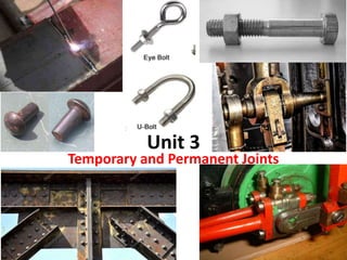
- 1. Unit 3 Temporary and Permanent Joints
- 5. Unit Split up 1. Threaded fasteners – Bolted joints including eccentric loading 2. Riveted joints 3. Welded joints 4. Theory of bonded joints 5. Knuckle joints 6. Cotter joints
- 6. What is Riveted Joints?
- 8. Methods of riveting • Cold riveting • Hot riveting
- 9. Types of Riveted Joints • Lap joint • Butt joint
- 10. Removal
- 11. Types of fastening elements
- 12. Screw, Fastners and Non-permanent Joints • Nomenclature
- 13. Forms of Screw Threads
- 14. 11/27/2022 14 Bolted joint applications
- 16. 16 Bolted joints in piping connections
- 18. 18 Bolted joints in piping connections
- 19. 19 Bolted joints in couplings
- 20. 20 Bolted joints in couplings
- 21. 21 Bolted joints in grooved couplings
- 22. 22 Hydraulic nut
- 23. 23 Bolts in wind mill
- 24. 24 Bolts in wind mill construction
- 25. 25 Bolts in wind mill construction
- 26. 11/27/2022 26 Steam engine working concept
- 27. 27 Bolted joint applications – steam engines
- 28. 28 Bolt failures
- 29. 29 Bolt failures
- 30. 30 Bolt failures
- 31. 31 Bolt failures
- 32. Threads • Thread – Helical ridge of uniform section formed on inside or outside of cylinder or cone • Used for several purposes: – Fasten devices such as screws, bolts, studs, and nuts – Provide accurate measurement, as in micrometer – Transmit motion – Increase force 32
- 34. Thread Terminology • Screw thread – Helical ridge of uniform section formed on inside or outside of cylinder or cone • External thread – Cut on external surface or cone • Internal thread – Produced on inside of cylinder or cone 34
- 35. Thread Terminology 35 Major Diameter Commonly known as the outside diameter . On a screw thread, the major diameter is the largest diameter of the thread on the screw or nut.
- 36. Thread Terminology 36 Number of Threads The number of threads per inch.
- 37. Thread Terminology Pitch The distance from a given point on one thread to a corresponding point on the very next thread 37
- 38. Thread Terminology 38 Single Lead Double Lead
- 39. Thread Terminology Crest – Top surface joining two sides of thread – External thread on major diameter – Internal thread on minor diameter 39
- 40. Brown & Sharpe Worm Thread Used to mesh worm gears and transmit motion between two shafts at right angles to each other but not in same plane 40 D = .6866P F = .335P C = .310P
- 41. Square Thread • Being replaced by Acme thread because of difficulty in cutting it • Often found on vises and jack screws 41 D = .500P F = .500P C = .500P + .002
- 42. The Three-Wire Method of Measuring 60º Threads 42
- 44. Thread Spec
- 45. Stress on Screwed Fasteners • Internal Stress due to screwing up forces • Stress due to External Forces (Mostly for eccentric) • Stress due to combination of internal and external forces.
- 46. Internal Stress on Screw • Bolts designed on the basis of direct tensile forces with large FOS in order to take the indeterminate (Unknown) stresses that are going to occur over it. • Internal stress/Initial tightening stress 𝑜𝑛 𝑏𝑜𝑙𝑡, 𝑃𝑖 = 2840 𝑑 • d – Nominal dia of bolt.
- 47. External Forces on Bolt (Same for rivets) • Tensile Load (Max Safe axial load) – P = /4 dc 2 t (Stress = load/ Area) – P = /4 (dc +dp)2 t (If PCD given) – dc - Root dia of thread – P = /4 dc 2 t x n (no of bolts) • Shear Load – Ps = /4 d2 x n – d = Major dia of bolt
- 48. Combined tensile and shear stress • max = ½ t 2 + 4 2
- 49. General Design of threaded fasteners • Core area of thread, 𝐴𝑐 = [ 60 𝑃𝑏 𝜎𝑦 ] 2 3 • Pb – Total load on bolt • Pb = Pi + P . (stiffness factor K) • Pi – Pre load/Initial load, (2840d) • Tightening torque, T = k x Pi x d • k – Torque coefficient factor (0.3), d – dia of bolt
- 50. Problem on Threads using General Formula A steam engine of effective diameter 300mm is subjected to a steam pressure of 1.5N/mm2. The cylinder head is connected by 8 bolts having yield point 330MPa and endurance limit at 240MPa. The bolts are tightened with an initial preload of 1.5 times of steam load. Assume a FOS of 2, find the size of bolt required take stiffness factor for a copper gasket may be taken as 0.5.[May 2016 & Dec 2017]
- 51. Approach to General Problems on thread • If we calculate Area, from PSG 5.42, bolt size is calculated. • Core area of thread, 𝐴𝑐 = [ 60 𝑷𝒃 𝜎𝑦 ] 2 3 • Pb – Total load on bolt (If FoS is given, x it) • Pb = Pi + P x (stiffness factor K) • Pi – Pre load/Initial load = 1.5.P (Given in ques) • P = Pressure x Area (Calculate load on each bolt)
- 53. • Approach: • Total load on bolt = Pi + P*q • Use Ac formula • Compare Area with bolt size from PSG 5.42
- 55. Problems on Bolt due to Eccentric loading • Due to eccentric loading the bolt Shear and fail. • Two loads acting: 1. Primary load (Direct Shear load) and 2. Secondary load (Shear due to torsion)
- 56. Loads acting on Bolt (Due to eccentric loading condition) • Primary shear load Secondary shear load Free body diagram
- 57. Stress on bolt • Direct shear load (F1)
- 58. Due to Torsion
- 59. Secondary shear Load • Ps2 (F2) = P .e. r / n. r 2 • Ps2 (F2)= P .e / n. r (If bolt is same dia) • r = r1 = r2 = r3= r4 • If bolts are of different radius – Ps2 = P .e r1 / r1 2 + r2 2 + r3 2 + r4 2
- 60. Loads acting on Bolt • Primary shear load Secondary shear load
- 61. Resultant Load on each bolt • W or FR or PR= Ps12 + Ps22 + 2 Ps1 Ps2 Cosθ • W or FR or PR= 𝐹1 2 +𝐹2 2 + 2 𝐹1𝐹2𝐶𝑜𝑠𝜃
- 62. Approach • By seeing the loading condition, you need to identify whether it will fail due to torsion and shear or shear alone Mandatory • In the given loading condition, we can easily say that it will fail only due to shear whereas the torsion is arrested due to the eccentric design setup and the place where load is acting. • Here the stresses (Bending & Torsion) are combined at the eccentric point which leads to principle stresses way of solving the problem. i.e., Stresses are not combined at the bolt but at the eccentric point where load is acting. • Upper row of two bolts exert the force initially then the bottom row bolts will exert.
- 63. 4 types of Eccentric Loading 1. Load acting parallel to axis of bolt 2. Load acting perpendicular to the axis of bolt 3. Plane containing the bolts 4. Loading on bolts on circular base
- 64. Load acting parallel to axis of bolt
- 65. Load acting perpendicular to the axis of bolt
- 66. Plane containing the bolts
- 67. Loading on bolts on circular base
- 68. Remember (In Eccentric loading) • For Parallel & Perpendicular to the axis of bolts (Type 1 & 2) – 𝜏𝑚𝑎𝑥 = 1 2 𝜎2 + 4 𝜏2 will be used • For Plane containing the bolt & Circular bolts – 𝜏𝑚𝑎𝑥 = 1 2 𝜎2 + 4 𝜏2 won’t be used
- 69. Remember (Another Way) • For this type of eccentric loading • 𝜏𝑚𝑎𝑥 = 1 2 𝜎2 + 4 𝜏2 from this find “d” -------------------------------------- • For this of type of eccentric loading • = Load/Area * n • W or FR or PR= 𝐹1 2 +𝐹2 2 + 2 𝐹1𝐹2𝐶𝑜𝑠𝜃
- 70. Design the size of Bolt for the following eccentric loading given:
- 71. Approach to eccentric type problems • = Load/Area * n • W or FR or PR= 𝑭𝟏 𝟐 +𝑭𝟐 𝟐 + 2 𝐹1𝐹2𝐶𝑜𝑠𝜃 • 𝐹1 = 𝐿𝑜𝑎𝑑 𝑛𝑜 𝑜𝑓 𝐵𝑜𝑙𝑡𝑠 • 𝐹2 = 𝑃.𝑒.𝒓 𝜀𝑟2 • Find r from Free body diagram
- 72. Design the size of Bolt for the following eccentric loading given:
- 74. Secondary shear load • T = W x e • T = 100 x 600 • T = 60,000 kN Factor • C* = T / r 2 60,000/4*106^2 = 1.333 • PS2 = 1.333 * 106.06 = 141.05 KN
- 75. Free body diagram with Loads 25 kN 141.05 kN
- 76. Resultant Load on each bolt 1 & 2 Resultant Load on each bolt 3 & 4 • W or FR or PR= Ps12 + Ps22 + 2 Ps1 Ps2 Cosθ (θ = 45) • W1 = W2 = 160 kN • W or FR or PR= Ps12 + Ps22 + 2 Ps1 Ps2 Cosθ (θ = 135) • W3 = W4 = 130 kN • Max load, W = 160 kN • W = /4 * d2 * (150) * 4 • d = 56 mm (Standardize from PSG DB 5.44) • Result: Dia of bolt is 56 mm
- 77. The structural connection shown in Fig. is subjected to an eccentric force P of 10 kN with an eccentricity of 500 mm from the CG of the bolts. The centre distance between bolts 1 and 2 is 200 mm, and the centre distance between bolts 1 and 3 is 150 mm. All the bolts are identical. The bolts are made from plain carbon steel 30C8 (Syt = 400 N/mm2) and the factor of safety is 2.5. Determine the size of the bolts. (APR/MAY 2018)
- 78. Approach • Same as previous problem except • r = 1002 + 752 (The CG is not of equidistance) • W = 𝐹1 2 +𝐹2 2 + 2 𝐹1𝐹2𝐶𝑜𝑠𝜃 – Since r is different, 𝐶𝑜𝑠 𝜃 = 𝐴𝑑𝑗 𝐻𝑦𝑝
- 79. Given: • P = 10,000 N • e = 500 mm, = 80 MPa • n = 4 bolts (different ‘θ’) To Find: Design size of bolt
- 80. P = 10,000 N, e = 500 mm, n = 4 bolts (different θ) Approach: 1. Primary and 2. Secondary forces 3. Resultant force 4. Find dia using Shear force formula
- 81. P = 10,000 N, e = 500 mm, n = 4 bolts (different θ) 752+1002 2.5 kN 10 kN
- 82. P = 10,000 N, e = 500 mm, n = 4 bolts (different θ), = 80 MPa • W or FR = /4 * d2 * • 12,093 = /4 * d2 * 80 • d = 13.87 mm • d = 16 mm (Standardize from PSG DB 5.42) • Result: M16 bolt
- 83. Same type of problem in Rivets • A machine frame is subjected to a load of 10kN from at 500 mm eccentrically. The distance between the each rivet is 200mm. The max shear stress is 75MPa.Determine the dia of rivet.
- 84. Approach • Same as Bolt problem • Instead or notation “r”, “l” is used. • Finding the centroid point different procedure as centroid point is not given. • Direct Load, Pd= Load / Area • Load due to Torsion,
- 87. F = P .e . l / 4. l^2
- 90. A wall bracket as shown in the figure is fixed to a vertical wall by 4 bolts. Find the size of the bolt with permissible shear stress 70MPa.
- 91. Approach • By seeing the loading condition, you need to identify whether it will fail due to torsion and shear or shear alone Mandatory • In the given loading condition, we can easily say that it will fail only due to shear whereas the torsion is arrested due to the eccentric design setup and the place where load is acting. • Here the stresses (Bending & Torsion) are combined at the eccentric point which leads to principle stresses way of solving the problem. i.e., Stresses are not combined at the bolt but at the eccentric point where load is acting. • Upper row of two bolts exert the force initially then the bottom row bolts will exert.
- 92. Remember (In Eccentric loading) • If the loading is perpendicular to the axis of bolts • 𝜏𝑚𝑎𝑥 = 1 2 𝜎2 + 4 𝜏2 from this find “d” ---------------------------------------------------------------- • If the loading is on the plane to the axis of bolts • = Load/Area * n • W or FR or PR= 𝐹1 2 +𝐹2 2 + 2 𝐹1𝐹2𝐶𝑜𝑠𝜃
- 93. Remember (Another Way) • For this type of eccentric loading • 𝜏𝑚𝑎𝑥 = 1 2 𝜎2 + 4 𝜏2 from this find “d” -------------------------------------- • For this of type of eccentric loading • = Load/Area * n • W or FR or PR= 𝐹1 2 +𝐹2 2 + 2 𝐹1𝐹2𝐶𝑜𝑠𝜃
- 94. Approach • So, we need to find Load on 1st & 2nd set of rows of bolts separately and find the max one in those. (Formula when load is acting perpendicular to axis of bolt), • Ps1 = P .e l1 / n1. l1 2 + n2 l2 2 & Ps2 = P .e l2 / n1. l1 2 + n2 l2 2 • Then find 𝜎 = 𝑀𝑎𝑥 𝐿𝑜𝑎𝑑 𝐴𝑟𝑒𝑎 & 𝜏 = 𝑀𝑎𝑥 𝐿𝑜𝑎𝑑 𝐴𝑟𝑒𝑎 ∗𝑁𝑜 𝑜𝑓 𝑏𝑜𝑙𝑡 • 𝜏𝑚𝑎𝑥 = 1 2 𝜎2 + 4 𝜏2 from this find “d” • Lastly, from PSG 5.42, find the size of bolt. Note: For these type of problems, no need to find CG
- 96. x
- 99. A bracket is attached to the wall by 5 bolts.3 at the top and 2 at the bottom as shown in fig. A vertical load of 25 kN is acting at 200mm eccentrically from the plane of bolt. Calculate the suitable size of bolt if permissible shear stress is 50 N/mm2.
- 100. Approach • Methodology same as previous problem. • Only n1 & n2 differs.
- 105. AU Problem on Bolts & Rivets Figure shows a solid forged bracket to carry a vertical load of 13.5 kN applied through the centre of hole. The square flange is secured to the flat side of a vertical stanchion through four bolts. Estimate the tensile load on each top bolt and the maximum shearing force on each bolt. Find the bolt size, if the permissible stress is 65 MPa in shear. All dimensions in mm (NOV/DEC 2016)
- 106. Approach • 𝜏𝑚𝑎𝑥 = 1 2 𝜎2 + 4 𝜏2 • 𝜏 = Resultant load/Area*n • 𝜎 = Resultant load/Area • FR= 𝐹1 2 +𝐹2 2 + 2 𝐹1𝐹2𝐶𝑜𝑠𝜃 • F1 = P/n • F2 = P.e/n.r
- 112. Approach • 𝜏𝑚𝑎𝑥 = 1 2 𝜎2 + 4 𝜏2 • 𝜏 = Shear load/Area • 𝜎 = Direct load/Area • Shear load = P/n • Direct load =
- 116. Rivets
- 124. AU Problem on Bolts & Rivets • A cast iron bracket, as shown in figure, supports a load of 10 kN. It is fixed to the horizontal channel by means of four identical bolts, two at A and two at B. The bolts are made of steel 30C8 whose yield strength is 400 MPa and the factor of safety is 6. Determine the major diameter of the bolts if dc = 0.8d. (NOV/DEC 2020 AND April/May 2021)
- 125. AU Problem on Bolts & Rivets • The structural connection shown in Fig. is subjected to an eccentric force P of 10 kN with an eccentricity of 500 mm from the CG of the bolts. The centre distance between bolts 1 and 2 is 200 mm, and the centre distance between bolts 1 and 3 is 150 mm. All the bolts are identical. The bolts are made from plain carbon steel 30C8 (Syt = 400 N/mm2) and the factor of safety is 2.5. Determine the size of the bolts. (APR/MAY 2018)
- 126. AU Problem on Bolts & Rivets Figure shows a solid forged bracket to carry a vertical load of 13.5 kN applied through the centre of hole. The square flange is secured to the flat side of a vertical stanchion through four bolts. Estimate the tensile load on each top bolt and the maximum shearing force on each bolt. Find the bolt size, if the permissible stress is 65 MPa in shear. All dimensions in mm (NOV/DEC 2016)
- 127. AU Problem on Bolts & Rivets • A steam engine of effective diameter 300 mm is subjected to a steam pressure of 1.5 N/mm2. The cylinder head is connected by 8 bolts having yield point 330 MPa and Endurance limit at 240 MPa. The bolts are tightened with an initial preload of 1.5 times the steam load. A soft copper gasket is used to make the joint leak proof. Assuming a factor of safety 2, find the size of bolt required. The stiffness factor for copper gasket may be taken as 0.5. (NOV/DEC 2015) (APR/MAY 2016)
- 128. AU Problem on Bolts • A steel plate subjected to a force of 5 kN and fixed to a channel by means of three identical bolts is shown in Fig. The bolts are made from plain carbon steel 45C8 (Syt = 380 N/mm2) and the factor of safety is 3. Specify the size of bolts. (NOV/DEC 2010)
- 129. AU Problem on Rivets Find the efficiency of a double riveted lap joint of 6 mm plates with 20 mm diameter rivets having a pitch of 55 mm. Assume Permissible tensile stress in plate is 120 MPa, Permissible shearing stress is 90 MPa and Permissible crushing stress is 180 MPa. (APR/MAY 2019)
- 130. Formulas for Rivet (Efficiency Prob) • Thickness of Cover plate, t1= 0.625 x t – t – thickness of plate • Diameter of rivet, d = 6.05√𝑡 • Pitch of rivet, P = 3 x d • Margin of rivet, e = 1.5 x d • Distance between adjacent rows of rivets, Pb = 3 x d • Efficiency of rivet, η = Least of Ft, Fs, Fc / P. t. σ • Shearing force, Fs = i . n. π/4 d^2. τ – i = 2 for double rivet, n = 1 for lap joint • Tearing force, Ft = (P – d) x t x σ • Crushing force, Fc = i x d x t x σ
- 131. AU Problem on Rivets Design a double riveted butt joint with two cover plates for the longitudinal steam of a boiler shell 1.5 m in diameter subjected to a steam pressure of 0.95 N/mm2. Assume joint efficiency as 75%, allowable tensile stress in the plate 90 MPa; Compressive stress 140 MPa and Shear stress in the rivet 56 MPa. (NOV/DEC 2016)
- 132. AU Problem on Bolts & Rivets A wall crane with a pin joint tie rod is as shown in Fig. The crane hook is to take a maximum load 35 kN, when the load is at a distance of 2 m from the wall. The tie rod and pin are made of steel FeG 250 (Syt = 250N/mm) and the factor of safety is 5. Calculate the diameter of the tie rod and the pin. (APR/MAY 2017)
- 133. AU Problem on Rivets Design a double riveted butt joint with two cover plates for the longitudinal steam of a boiler shell 1.5 m in diameter subjected to a steam pressure of 0.95 N/mm2. Assume joint efficiency as 75%, allowable tensile stress in the plate 90 MPa; Compressive stress 140 MPa and Shear stress in the rivet 56 MPa. (NOV/DEC 2016)
- 134. AU Problem on Bolts & Rivets (Part C) A steel plate is subjected to a force of 5 kN and fixed to a channel by means of 3 identical bolts as shown in figure. The bolts are made from plain carbon steel for which yield stress in tension is 380 N/mm2 and factor of safety is 3. Determine the size of the bolts. (15) (NOV/DEC 2018)
- 135. AU Problem on Bolts & Rivets (Part C) • A bracket is bolted to a column by six bolts as shown in fig. It carries a load of 50 KN at a distance of 150 mm, from the center of column. If the maximum stress in the bolts is to be limited to 150 MPa, determine the diameter of the bolt. (NOV 2021)
- 136. AU Problem on Bolts & Rivets (Part C) Fig shows a bracket fixed on a steel column by means of 3 bolts of same size. If the permissible tensile and shear stress are limited to 75 N/mm2 and 55 N/mm2 respectively. Find the size of bolts. (NOV/DEC 2017)
- 137. Welding
- 138. Welding • A welded joint is a permanent joint which is obtained by the fusion of the edges of the parts to be joined together, with or without the application of pressure and a filler material. • The heat required for the fusion of the material is obtained by burning gas(gas welding) or by an electric arc(electric arc welding). • Welding is extensively used in fabrication as an alternative to riveted and bolted joints. • Welding also used as a repair medium
- 140. Types of welding processes • Heat – Fusion welding • Thermit welding, Gas welding and Electric arc welding (Shielded arc and Unshielded arc). • Heat and Pressure • Forge welding • Diffusion welding
- 141. Types of Welded Joints 1. Lap Joint • The lap joint or the fillet joint is obtained by overlapping the plates and then welding the edges of the plates. The cross‐section of the fillet is approximately triangular. The fillet joints may be 1. Single transverse fillet, 2. Double transverse fillet, and 3. Parallel fillet joints.
- 142. Butt Joint • The butt joint is obtained by placing the plates edge to edge. In butt welds, the plate edges do not require beveling if the thickness of plate is less than 5 mm. On the other hand, if the plate thickness is 5 mm to 12.5 mm, the edges should be beveled to V or U‐groove on both sides. The butt joints may be • 1. Square butt joint, • 2. Single V‐butt joint • 3. Single U‐butt joint, • 4. Double V‐butt joint, and • 5. Double U‐butt joint
- 144. Other Joints • The other type of welded joints are corner joint, edge joint and T‐joint as shown in Fig. below. The main considerations involved in the selection of weld type are: 1. The shape of the welded component required, 2. The thickness of the plates to be welded, and 3. The direction of the forces applied.
- 145. Refer PSG 11.1 – Weld Symbols
- 147. Strength of Transverse Fillet Welded Joints • The transverse fillet welds are designed for tensile strength. • Let us consider a single and double transverse fillet welds as shown in Fig. (a) and (b) respectively.
- 148. In order to determine the strength of the fillet joint, it is assumed that the section of fillet is a right angled triangle ABC with hypotenuse AC making equal angles with other two sides AB and BC. • The enlarged view of the fillet is shown in Fig. below The length of each side is known as leg or size of the weld and the perpendicular distance of the hypotenuse from the intersection of legs (i.e. BD) is known as throat thickness. The minimum area of the weld is obtained at the throat BD, which is given by the product of the throat thickness and length of weld. t = Throat thickness (BD),s = Leg or size of weld,= Thickness of plate, and l = Length of weld,
- 150. From Fig. below, we find that the throat thickness, Cos 45 = t/s t = 0.707 s (In few books, t = 0.707 h) Minimum area of the weld or throat area, A = Throat thickness × Length of weld = t × l = 0.707 s × l If σt is the allowable tensile stress for the weld metal, then the tensile strength of the joint for single fillet weld, F = Throat area × Allowable tensile stress = 0.707 s × l × σt and tensile strength of the joint for double fillet weld, F = 2 × 0.707 s × l × σt = 1.414 s × l × σt D 45 h or s h or s t h or s h or s
- 151. • The parallel fillet welded joints are designed for shear strength. Consider a double parallel fillet welded joint as shown in Fig. (a). The minimum area of weld or the throat area, A = 0.707 s × l • If τ is the allowable shear stress for the weld metal, then the shear strength of the joint for single parallel fillet weld, F = Throat area × Allowable shear stress = 0.707 s × l × τ and shear strength of the joint for double parallel fillet weld, F = 2 × 0.707 × s × l × τ = 1.414 s × l × τ F = 0.707 s × l × τ F = 2 x 0.707 s × l × τ F = 1.414 s × l × τ F = 2 x 0.707 s × l × τ F = 1.414 s × l × τ
- 161. Here t is the thickness of the plate. The torque P . e will cause secondary shearing stress τ at the weld end, A, which will be greater than shearing stress at any other point in the weld, A is at a distance of R from CG. It can be shown that G = P e r2 /J Here, J is the polar moment of inertia of fillet weld about G. AS shown in Figure , τ1 and τ2 at A act at an angle θ. Since nature of both these stresses is same, they can be added vectorially. The resultant stress τA is τ max = [τ1 2 + τ2 2 + 2 τ1 τ2 cosθ]½, cos θ = r1/r2
- 162. PSG DB 11.3 Stress in Weld joints
- 163. PSG DB 11.5 & 11.6 Properties of Weld treated as Line
- 165. Approach • Length of transverse Weld, l1 = b- t • σt = P1 / A1, P1 – Load by single transverse weld • P = P1 + P2 • τ = P2 /A2, P2 – Load by double parallel weld • A2 = 2 x 0.707 x h x l2
- 168. Welding Joints under Eccentric Loading 1. Weld Joints subjected to moment acting on the plane (Bending & Shear Stress) 2. Weld Joints subjected to moment acting normal to the plane 3. Weld Joints subjected to direct shear, bending and torsional
- 169. General formula for Welding • 𝜏𝑚𝑎𝑥 = 1 2 𝜎𝑏 2 + 4 𝜏2 • 𝜎𝑏 = 𝑀𝑏 𝑍 , – Mb – Bending Moment (PxL) = Load x distance – Z – Sectional modulus – PSG 11.5 & 11.6 (In that page, “t” has to be multiplied) • 𝜏 = 𝐿𝑜𝑎𝑑 𝐴𝑟𝑒𝑎 , Area should be multiplied by “t” • Refer PSG 11.3 to 11.6 pages for other formula
- 170. Case 1 - Weld Joints subjected to moment acting on the plane
- 173. Approach • 𝜏𝑚𝑎𝑥 = 1 2 𝜎𝑏 2 + 4 𝜏2 • 𝜏 = 𝐿𝑜𝑎𝑑 𝐴𝑟𝑒𝑎 • A = t(2b+2d) = 0.707 h (2b+2d) • 𝜎𝑏 = 𝑀𝑏 𝑍 , – Mb = P x L – For Z – PSG 11.6 (multiply with “t”) – Ans will be in terms of “h”
- 176. Case 3 - Weld Joints subjected to direct shear, bending and torsional
- 177. Approach • 𝜏𝑚𝑎𝑥 = 1 2 𝜎𝑏 2 + 4 𝜏2 • 𝜏 = 𝐿𝑜𝑎𝑑 𝐴𝑟𝑒𝑎 • A = π𝐷 x t • 𝜎𝑏 = 𝑀𝑏 𝑍 • Mb = P x L – For Z – PSG 11.6 (multiply with “t”) – Ans will be in terms of “h”
- 182. Case 2 - Weld Joints subjected to moment acting normal to the plane
- 184. Eccentric load in Welding Direct Shear Stress • Direct shear load (F1)
- 185. Due to Bending
- 186. Remember (In Eccentric loading Case 2) • Direct Shear, 𝜏1 = 𝑃 𝐴 • Shear due to Torsion, 𝜏2 = 𝑀𝑡 ∗ 𝒓 𝐽 – 𝑀𝑡 = Load x eccentric distance (e) – J – PSG 11.5 • Resultant Shear Stress, 𝜏𝑟= 𝜏1 2 +𝜏2 2 + 2 𝜏1𝜏2𝐶𝑜𝑠𝜽
- 190. Theory of Bonded Joints
- 192. Types of Loads on adhesive joints
- 193. Types of adhesive bonding
- 195. Knuckle joint Two or more rods subjected to tensile and compressive forces are fastened together Their axes are not in alignments but meet in a point The joint allows a small angular moment of one rod relative to another It can be easily connected and disconnected Applications: Elevator chains, valve rods, etc
- 201. PSG additional pages
- 202. Design of Knuckle joints (Failures) 1. Rod 1. Tensile load 2. Single eye end 1. Tensile load 2. Shearing load 3. Crushing load 3. Double eye end 1. Tensile load 2. Shearing load 3. Crushing load 4. Knuckle Pin 1. Double Shear load
- 204. Design of Knuckle joints Step 1 – Design of Rod
- 205. Design of Knuckle joints Step 2.1 – Design of Single eye end
- 206. Design of Knuckle joints Step 2.2 – Design of Single eye end • Shearing load
- 207. Design of Knuckle joints Step 2.3 – Design of Single eye end • Crushing Load
- 208. Design of Knuckle joints Step 3.1 – Design of Double eye end
- 209. Design of Knuckle joints Step 3.2 – Design of Double eye end • Shear load
- 210. Design of Knuckle joints Step 3.3 – Design of Double eye end • Crushing load
- 211. Design of Knuckle joints Step 4 – Design of Knuckle Pin
- 217. Cotter joints • A cotter is a flat wedge-shaped piece of steel • This is used to connect rigidly two rods which transmit motion in the axial direction, without rotation. • These joints may be subjected to tensile or compressive forces along the axes of the rods • It is uniform in thickness but tapering in width , generally on one side only. Usually the taper is 1 in 30.
- 218. Applications: Piston rod to the crosshead of a steam engine, Piston rod and its extension as a tail or pump rod Valve rod and its stem Strap end of connecting rod Foundation bolts to fasten heavy machinery to foundations …..etc., Cotter joints
- 219. Cotter joints
- 220. TYPES • Socket and Spigot cotter joint • Sleeve and cotter joint • Gib and cotter joint
- 221. Sleeve and cotter joint The enlarged ends of the rods butt against each other with a common sleeve over them •The rod ends are enlarged to take care of the weakening effect caused by slots For circular rods
- 222. Socket and Spigot Cotter Joint Slots are wider than the cotter. Cotter pulls the rod and socket tightly together Clearance: must be provided for adjustment.(2 to 3 mm) Proportions cotter thickness = (1/3)diameter of rod cotter width = rod diameter
- 223. Gib and cotter joint for rectangular rods One bar end is made in the form of a strap A Gib is used along with the cotter. The thickness of the gib and cotter are same
- 224. Gib and cotter joint for rectangular rods When the cotter alone (i.e. without gib) is driven, the friction between its ends and the inside of the slots in the strap tends to cause the sides of the strap to spring open (or spread) outwards as shown dotted in Fig.
- 226. Design of Socket and Spigot Cotter Joint .
- 227. Design of Socket and Spigot Cotter Joint • Design of Shaft – Tensile force • Design of Spigot – Tensile force – Crushing force • Design of Cotter – Crushing – Shear • Design of Socket – Tensile – Shear
- 228. Let P = Load carried by the rods, • d = Diameter of the rods, • d1 = Outside diameter of socket, • d2 = Diameter of spigot or inside diameter of socket, • d3 = Outside diameter of spigot collar, • t1 = Thickness of spigot collar, • d4 = Diameter of socket collar, • c = Thickness of socket collar, • b = Mean width of cotter, • t = Thickness of cotter, • l = Length of cotter • a = Distance from the end of the slot to the end of rod, • σt = Permissible tensile stress for the rods material • τ = Permissible shear stress for the cotter material • σc = Permissible crushing stress for the cotter material Design of Socket and Spigot joint
- 230. 1.Failure of the rods in tension Design of Socket and Spigot Cotter Joint P P
- 231. 2. Failure of spigot in tension across the weakest section (or slot) Design of Socket and Spigot Cotter Joint
- 232. 3. Failure of the rod or cotter in crushing Design of Socket and Spigot Cotter Joint
- 233. 4.Failure of the socket in tension across the slot Design of Socket and Spigot Cotter Joint
- 234. 5. Failure of cotter in shear Design of Socket and Spigot Cotter Joint
- 235. 6. Failure of the socket collar in crushing Design of Socket and Spigot Cotter Joint
- 236. 7. Failure of socket end in shearing Design of Socket and Spigot Cotter Joint
- 237. 8. Failure of rod end in shear Design of Socket and Spigot Cotter Joint
- 238. 9.Failure of spigot collar in crushing Design of Socket and Spigot Cotter Joint
- 239. 10. Failure of the spigot collar in shearing Design of Socket and Spigot Cotter Joint
- 240. 11. Failure of cotter in bending Design of Socket and Spigot Cotter Joint
- 255. Unit 3 Temporary and Permanent Joints Bolted joints Rivted joints Welded joints Knuckle joints Cotter joints
- 256. End