1. Table of contents:
GATPBP101 Basement Plan
GATPGF102 Ground Floor Plan
GATPFF103 First Floor Plan
GATPAV118 Axonometric Views
GATPENE104 East & North Elevation
GATPWSE105 West & South Elevation
GATPSV106 Section Views
GATPSD107 Section One Details
GATPKD108 25m Pool Kalzip Roof Details
GATPCD109 Cantilever Details
GATPCD110 Curtain Walling Details
GATPCD111 Curtain Walling Details
GATPRD112 Roof Meeting Curtain Walling
GATPSD113 Section Two Details
GATPWD114 Wall Details
GATPTGDMC115 Building Regulations Part M
GATPTGDKC116 Stairs Building Regulaions
GATPTGDBC117 Building Regulations Part B
GATPSS119 Sustainable Building Services
GATPIV120 Internal Views
GATPCD121 Concept Design
GATPEA122 Energy Analysis
Curtain Walling Specification:
Curtain Wall CW 50
• Manufacturer: Reynaers Ltd
• Product reference: Curtain Wall CW 50
Standard
/Curtain Wall CW 50-FP EW 30
/Curtain Wall CW 50-FP EW 60 /Curtain
Wall CW
50- HL /Curtain Wall CW 50-RA
• Internal framing member: Extruded
aluminium
- Finish: Anodized /Polyester powder
coated
- Colour:
- Minimum film thickness:
• External cover cap: Extruded aluminium
- Finish: Anodized /Polyester powder
coated
- Colour:
- Minimum film thickness:
• Doors:
• Windows: Fixed light (CW50-FP) /Glazed
in windows/Structural glazing
- Configuration: Horizontal pivot /Parallel
opener /Side hung /Tilt and turn /Top hung
• Glazing: Insulating glass units /Single
glazed panes
• Glazing system: Dry glazed gasket
• Panel/ Facing type:
Tegral Natura fibrecement
cladding panels:
-Tegral Natura fibre cement
cladding panels are to be applied to
all elevations of the building as the
external finish.
-Cladding panels to be 12mm thick.
-To be in compliance with EN
12467.
-Cladding panels to be used in
accordance with Tegframe light
gauge steel framing system.
-Panels are to have rivet fixings
back to the secondary steel frame.
-Fixings must be a minimum of
80mm from the corner of each
panel.
-A minimum of an 8mm shadow
gap must be left between each
panel to create the effect of a secret
fixing system.
-A mi9x and match of three coloured
cladding panels to be used
throughout the building.
• Tegral Natura White N191
• Tegral Natura Yellow N683
• Tegral Natura Blue N473
-All works to be done to
manufacturers specifications.
Wall Build Up
12mm Tegral Natura fibre cement cladding panels,
Breather membrane, 40mm Vertical steel c sections
@ 600mm c/c, 100mm Tegral system steel frame,
12mm cement particle board, 150mm Kingspan
kooltherm k15 rainscreen board, vapour barrier,
18mm internal plywood finish.
Fire rated wall build up
12mm Tegral Natura fibre cement cladding panels,
Breather membrane, 40mm Vertical steel c sections
@ 600mm c/c, 100mm Tegral system steel frame,
65mm precast concrete solid wall slab, 150mm
Kingspan kooltherm k15 rainscreen board,
vapour barrier, 18mm internal plywood finish.
Basement wall build up
100mm Block non-load bearing inner wall, 50mm
deltadrain drained cavity, reinforced cast in situ concrete
wall, 20mm thick vertical asphalt applied in three coats,
finished with 30mm thick sand/cement grout.
Floor build up
150mm Precast concrete hollow core floor slab,
150mm Kingspan kooltherm k3 floorboard, finished
with 75mm cast in situ concrete screed.
Basement floor build up
75mm Cast in situ concrete screed, damp proof
membrane, 75mm precast concrete 'dryangle' floor
tiles,
reinforced cast in situ concrete floor slab, 50mm
thick
cement sand protective screed, 30mm thick
horizontal
asphalt applied in three coats, finished with 100mm
thick mass concrete base.
Copper roof build up
20mm copper roof covering, 150mm loose
insulation in between roof standing seam
clips to fix roof into place, vapour barrier,
38mm metal decking, steel purlins running
the length of the roof, finished with 18mm
internal plywood finish.
Kalzip roof build up
Kalzip aluminium roof covering, 150mm loose
insulation in between roof standing seam
clips to fix roof into place, vapour barrier, 38mm
metal decking, 38mmx 140mm glulam
purlins, finished with18mm internal plywood in
between glulam beams to leave the glulam
beams partially exposed.
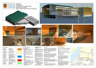
Edel Fox
C00146668
Architectural Technology Year 3
Thesis Leisure Centre
Dan O' Sullivan, Noel Dunne & Allan Read
2. UP
1
2
3
4
5
6
7
8
9
10
11
12
13 14 15 16 17 18 19
20 21
22 23
24 25
26 27
28 29
30 31
32 33
34 35
Outline of leisure pool above
Outline of 25m pool above
Outline of building above
30 m²
Pool pump room
8
31 m²
Wood pellet burner
room
9
6000
Refuge Point
Call Point
10465
3600
6000
1800mm x
1800mm
clear space
in front of lift
Refuge Point
Call Point
1810mm x 2110mm FD 60
double doors
1810mm x 2110mm FD 60
double doors
7369
7150
Ramp to underground car park
at basement level @ slope 1:5.
Proposed one way traffic system.
Ramp floor to be made of a base
coat of asphalt to provide
waterproofing, top coat of
concrete
2300
4850
200mm concrete kerbs seperating
lanes on entrance/exit to the car park
2000
2000
2000mm pedestrian walkway
Specification:
General notes: All works must comply
with current building regulations and code
of practice. All works must be to the
satisfaction of the building control officer.
600mm concrete piles to be placed
appropriately in areas of weak soil.
Basement walls: 100mm cast in situ
concrete protective walling, 20mm thick
cement/sand grout, 30mm thick vertical
asphalt applied in three coats to rough
concrete face, 600mm cast in situ
reinforced concrete wall, 50mm deltadrain
drained cavity, finished with an internal
100mm block non-load bearing internal
wall.
Basement floor: 100mm cast in situ
concrete protective walling, 20mm thick
cement/sand grout, 30mm thick vertical
asphalt applied in three coats to rough
concrete face, cast in situ reinforced
concrete floor slab with edge thickening,
precast concrete 'dryangle' floor tiles,
damp proof membrane finished internally
with 75mm concrete screed.
Cast in situ walls and floors to comply
with BS 8004, with all reinforcement to be
approved by the structural engineer.
Structural columns to be reinforced
600mm diameter cast concrete,
reinforcing steel must have a minimum of
30mm concrete coverage. Concrete
columns to be wrapped in rubber
protectors between 150mm from finished
floor level to 1000mm above finished floor
level.
Doors: to plant room, lift and stairs to be
fully sealed and provide a minimum of 60
minute fire resitance. All fire escape
doors to be 60 minute fire rated and fitted
with automatic closers.
Proposed 33 standard car parking spaces
2300mm x 4850mm, plus 2 disabled
parking bays 3600mm x 6000mm beside
lift and stair shafts to provide easy
access. Proposed 2000mm pedestrian
walkway around car park leading to stairs
and lift shaft and shown.
600mm diameter
reinforced cast
concrete columns
Pedestrian crossing to walkway
600mm diameter retaining piles
UP
Room
Car Park
Pool Pump Room
Wood Pellet Burner Room
Stairs 1
Stairs 2 Plus Lift
Total Floor area:
Floor Area
1231.85msq
30msq
31msq
18.17msq
42.59msq
1353.61msq
Slope
1:5
FD 60FD 60
FD60
Scale
LECTURER
Drawn by
Date
Project number
Institute of Technology Carlow
BSc. in Architectural Technology
Year 3 2012-2013
1 : 100
Basement Plan
3
Thesis Leisure Centre
01-05-2013
Edel Fox
Dan O'Sullivan, Noel Dunne &
Allan Read
GATPBP101
1 : 100
Basement Level
1
Basement Door Schedule
Count Family and Type Height Level Mark Width
1 ExtDbl Flush: 1810 x 2110mm 2110 Basement 13 1810
1 ExtDbl Flush: 1810 x 2110mm 2110 Basement 14 1810
1 ExtDbl Flush: 1810 x 2110mm 2110 Basement 39 1810
1 ExtDbl Flush: 1810 x 2110mm 2110 Basement 42 1810
1 IntDbl (2): 1810 x 2110mm 2110 Basement 43 1810
123456789101112
242322212019181716151413
123456789101112
242322212019181716151413
3. DN
UP
UP
UP
1 2 3 4 5 6 7 8 9 10
B
C
D
E
F
H
I
J
G
K
325060006000233536656000600060006000
12330 17965 2700
1200
Squash Court Squash Court Squash Court
Sports Hall
66 m²
Room
1
66 m²
Room
2
67 m²
Room
3
A
Disabled WC & shower
room
1800mm x
1800mm
clear space
in front of lift
11 m²
First Aid
10
6 m²
Store Room
11
11 m²
Office
12
1545
10 m²
Hall Storage
13
Showers
Changing stalls
423 m²
Sports Hall
14
241 m²
Changing Village
15
6000
6000 6000 6000 6000 6000 8000 12330 17965 2700
Reception desk
Non slip ceramic tile finish
238 m²
Reception Area
23
26
22
23
20
13
6
131
3 4 5
16
29 28
21
25
24
2
27
19
17
18
15
30
78
1011
9
1214
32
Proposed timber flooring
Proposed timber flooring
DN
DN
16 m²
Male Toilets
28
16 m²
Female Toilets
30
6 m²
Disabled Toilets
31
6 m²
Disabled Toilets
32
44 m²
Pool Store
33
59 m²
Plant Room
34
10 m²
Steam Room
35
10 m²
Sauna
36
544 m²
25m Pool
37
165 m²
Leisure Swimming
Pool
39
31 m²
Viewing Room
40
15 m²
Draught Lobby
41
Non-slip ceramic tile floor finish
Proposed 2m concrete paving slab footpath around building
25m Pool
Leisure Pool
Changing Village
Sposts Hall
Sports Hall Changing Rooms
Reception Area
Squash Courts
Scale
LECTURER
Drawn by
Date
Project number
Institute of Technology Carlow
BSc. in Architectural Technology
Year 3 2012-2013
1 : 100
Ground Floor Plan
3
Thesis Leisure Centre
01-05-2013
Edel Fox
Dan O'Sullivan, Noel Dunne &
Allan Read
GATPGF102
1 : 100
Ground level
1
Ground Level Plan
2
Ground Floor Door Schedule
Count Family and Type Height Level Mark Width
1 IntDbl (2): 1810 x 2110mm 2110 Ground level 26 1810
1 ExtDbl Flush: 1810 x 2110mm 2110 Ground level 22 1810
1 ExtDbl Flush: 1810 x 2110mm 2110 Ground level 23 1810
1 ExtDbl Flush: 1810 x 2110mm 2110 Ground level 20 1810
1 IntDbl (2): 1810 x 2110mm 2110 Ground level 13 1810
1 ExtDbl Flush: 1810 x 2110mm 2110 Ground level 6 1810
1 Dbl Glass (1): Dbl Glass (1) 1850 Ground level 1 1900
1 ExtDbl Flush: 1810 x 2110mm 2110 Ground level 31 1810
1 Sgl Glass (3): Sgl Glass (3) 2130 Ground level 3 1000
1 Sgl Glass (3): Sgl Glass (3) 2130 Ground level 4 1000
1 Sgl Glass (3): Sgl Glass (3) 2130 Ground level 5 1070
1 IntSgl (1): 1010 x 2110mm 2110 Ground level 16 1010
1 IntSgl (1): 910 x 2110mm 2110 Ground level 29 910
1 IntSgl (1): 910 x 2110mm 2110 Ground level 28 910
1 ExtDbl Flush: 1810 x 2110mm 2110 Ground level 21 1810
1 IntSgl (1): 910 x 2110mm 2110 Ground level 25 910
1 IntSgl (1): 910 x 2110mm 2110 Ground level 24 910
1 Dbl Glass (1): Dbl Glass (1) 1950 Ground level 2 1900
1 IntSgl (1): 910 x 2110mm 2110 Ground level 27 910
1 IntDbl (2): 1810 x 2110mm 2110 Ground level 19 1810
1 IntSgl (1): 1010 x 2110mm 2110 Ground level 17 1010
1 IntSgl (1): 1010 x 2110mm 2110 Ground level 18 1010
1 IntSgl (1): 1010 x 2110mm 2110 Ground level 15 1010
1 IntDbl (2): 1810 x 2110mm 2110 Ground level 30 1810
1 IntDbl (2): 1810 x 2110mm 2110 Ground level 7 1810
1 IntSgl (1): 1010 x 2110mm 2110 Ground level 8 1010
1 IntSgl (1): 1010 x 2110mm 2110 Ground level 10 1010
1 IntSgl (1): 1010 x 2110mm 2110 Ground level 11 1010
1 IntSgl (1): 1010 x 2110mm 2110 Ground level 9 1010
1 IntDbl (2): 1810 x 2110mm 2110 Ground level 12 1810
1 IntDbl (2): 1810 x 2110mm 2110 Ground level 14 1810
1 IntDbl (2): 1810 x 2110mm 2110 Ground level 32 1810
General Specification:
-All works to comply with current building regulations and code of practice.
-All works must be done to the satisfaction of the buildign control officer.
-All dimensions in mm unless otherwise noted.
-Drawings must not be scaled, Dimensions to be followed.
-Cast insitu concrete for lift shaft and stair shaft to comply with BS 8004.
-Stair shaft to have a smooth concrete internal finish.
-Lift and stair shaft to be 60min fire proof including access doors.
-All structural steel to be 60min fire rated with intumescent paint.
-All escape fire doors to be 60min fire rated and fitted with automatic closers.
-Floor finish to be non-slip ceramic tiles and timber floors where indicated on plan.
-Entrance area to have a minimum level landing within 1800mm of entrance door.
Tegral Natura fibrecement cladding panels:
-Tegral Natura fibre cement cladding panels are to be applied to all elevations of the
building as the external finish.
-Cladding panels to be 12mm thick.
-To be in compliance with EN 12467.
-Cladding panels to be used in accordance with Tegframe light
gauge steel framing system.
-Panels are to have rivet fixings back to the secondary
steel frame.
-Fixings must be a minimum of 80mm from the
corner of each panel.
-A minimum of an 8mm shadow gap must be left
between each panel to create the effect of a
secret fixing system.
-A mi9x and match of three coloured
cladding panels to be used
throughout the building.
• Tegral Natura White N191
• Tegral Natura Yellow N683
• Tegral Natura Blue N473
-All works to be done to
manufacturers specifications.
1234567891011
12 212019181716151413
12345678910
11 12 2019181716151413
FD 60
FD 60
FD 60
FD 30
FD 60
12345678910
11122019181716151413
4. UP
UP
UP
1 2 3 4 5 6 7 8 9 10
B
C
D
E
F
H
I
J
G
K
6000 6000 6000 6000 6000 8000 12330 17965 2700
325060006000233536656000600060006000
Fitness Reception
A
6000
Void over 25m swimming pool
Void over leisure pool
24 m²
Male Changing Room
17
25 m²
Female Changing
Room
18
Void over squash court Void over squash court Void over squash court
1800mm x
1800mm
clear space
in front of lift
Refuge Point
Call Point
Refuge Point
Call Point
6 m²
Disabled WC &
Shower Room
19
585 m²
Room
First Aid 6 m²
Store Room
21
Redundant
Room
Office
22
Reception desk
Void over sports hall
Redundant
Room
Gym Area
47
44 m²
Gym Store
48
80 m²
Plant Room
49
36
33
34 35
3738
39
41 42
43
44
DN
FD60
FD 60 FD 60
FD 60
Roof over competition Pool
Roof over Leisure Pool
Gym area
Void over sports hall
Void over squash courts
Male and female changing rooms
Scale
LECTURER
Drawn by
Date
Project number
Institute of Technology Carlow
BSc. in Architectural Technology
Year 3 2012-2013
1 : 100
First Floor Plan
3
Thesis Leisure Centre
01-05-2013
Edel Fox
Dan O'Sullivan, Noel Dunne &
Allan Read
GATPFF103
1 : 100
First Floor Level
1
First Floor Door Schedule
Count Family and Type Height Level Mark Width
1 IntDbl (2): 1810 x 2110mm 2110 First Floor Level 33 1810
1 IntDbl (2): 1810 x 2110mm 2110 First Floor Level 34 1810
1 IntDbl (2): 1810 x 2110mm 2110 First Floor Level 35 1810
1 IntDbl (2): 1810 x 2110mm 2110 First Floor Level 36 1810
1 IntSgl (1): 1010 x 2110mm 2110 First Floor Level 37 1010
1 IntSgl (1): 1010 x 2110mm 2110 First Floor Level 38 1010
1 IntSgl (1): 1010 x 2110mm 2110 First Floor Level 39 1010
1 IntSgl (1): 910 x 2110mm 2110 First Floor Level 41 910
1 IntSgl (1): 910 x 2110mm 2110 First Floor Level 42 910
1 IntSgl (1): 910 x 2110mm 2110 First Floor Level 43 910
1 IntDbl (2): 1810 x 2110mm 2110 First Floor Level 44 1810
3D First Floor
2
123456789101112
22212019181716151413
General Specification:
-All works to comply with current building regulations
and code of practice.
-All works must be done to the satisfaction of the
buildign control officer.
-All dimensions in mm unless otherwise noted.
-Drawings must not be scaled, Dimensions to be
followed.
-Cast insitu concrete for lift shaft and stair shaft to
comply with BS 8004.
-Stair shaft to have a smooth concrete internal finish.
-Lift and stair shaft to be 60min fire proof including
access doors.
-All structural steel to be 60min fire rated with
intumescent paint.
-All escape fire doors to be 60min fire rated and fitted
with automatic closers.
-Floor finish to be non-slip ceramic tiles and timber
floors where indicated on plan.
-Entrance area to have a minimum level landing within
1800mm of entrance door.
Tegral Natura fibrecement cladding panels:
-Tegral Natura fibre cement cladding panels are to be
applied to all elevations of the building as the external
finish.
-Cladding panels to be 12mm thick.
-To be in compliance with EN 12467.
-Cladding panels to be used in accordance with
Tegframe light
gauge steel framing system.
-Panels are to have rivet fixings back to the
secondary
steel frame.
-Fixings must be a minimum of 80mm from the
corner of each panel.
-A minimum of an 8mm shadow gap must be left
between each panel to create the effect of a
secret fixing system.
-A mi9x and match of three coloured
cladding panels to be used
throughout the building.
• Tegral Natura White N191
• Tegral Natura Yellow N683
• Tegral Natura Blue N473
-All works to be done to
manufacturers specifications.
12345678910
11 12 2019181716151413
DN
12345678910
11122019181716151413
5. Ground level
46700
First Floor Level
50300
Level 2
53900
BCDEFHIJ GK
Level 3
55900
3250 6000 6000 2335 3665 6000 6000 6000 6000
A
Fire escape doors Clear glazing to allow natural light into the sports hall 12mm Tegral Natura fibre cement
cladding panels
Fire escape door
6000
200036003600
Proposed copper roof covering
wrapped back around to cover eaves
Proposed kalzip
roof covering
Top of copper roof
59450
3550
Ground level
46700
First Floor Level
50300
Level 2
53900
12345678910
Level 3
55900
2700 17965 12330 8000 6000 6000 6000 6000 6000
360036002000
Fir escape door
Main entrance glazed door
Tegral Natura 12mm fibre cement cladding panels
Clear glazing Curved copper roof
Proposed clear glazing curtain wall around
the Leisure pool to allow for natural light and
natural heat gain
Proposed passivent natural ventilators
to underside of the roof
Curved kalzip roof
Tegral Natura 12mm fibre cement cladding panels
Proposed kalzip
bullnose to eaves
Proposed copper roof covering wrapped around to cover eaves
Top of copper roof
59450
3550
Fire door
Clear glazing
Copper roof covering Kalzip roof covering
Clear glazing
Structural glazing to clearly
identify main entrance
12mm Tegral Natura fibre
cement cladding panels
North
East
Scale
LECTURER
Drawn by
Date
Project number
Institute of Technology Carlow
BSc. in Architectural Technology
Year 3 2012-2013
As indicated
East & North Elevation
3
Thesis Leisure Centre
01-05-2013
Edel Fox
Dan O' Sullivan, Noel Dunne &
Allan Read
GATPENE104
1 : 100
East Elevation
1
1 : 100
North Elevation
2
East Elevation Render
North Elevation Render
North-East Elevation
3
Tegral Natura fibrecement cladding panels:
-Tegral Natura fibre cement cladding panels are
to be applied to all elevations of the building as the
external finish.
-Cladding panels to be 12mm thick.
-To be in compliance with EN 12467.
-Cladding panels to be used in accordance with
Tegframe light gauge steel framing system.
-Panels are to have rivet fixings back to the
secondary steel frame.
-Fixings must be a minimum of 80mm from the
corner of each panel.
-A minimum of an 8mm shadow gap must be left
between each panel to create the effect of a
secret fixing system.
-A mi9x and match of three coloured cladding
panels to be used throughout the building.
• Tegral Natura White N191
• Tegral Natura Yellow N683
• Tegral Natura Blue N473
-All works to be done to manufacturers specifications
Tegral fibre cement cladding panels
6. Ground level
46700
First Floor Level
50300
Level 2
53900
B C D E F H I JG K
Level 3
55900
12000 6000 6000 3665 2335 6000 6000 3250
A
Top of copper roof
59450
3550200036003600
Copper roof covering wrapped back around at eaves
Kalzip roof covering with bullnose at eaves
Proposed glazing facing the river supported with
secondary steel structe hollw circular sections
12mm Tegral Natura fibre cement cladding panelsCurtain wall glazing to alloow in natural light and natural solar gainKalzip roof covering with bullnose at eaves12mm Tegral Natura fibre cement cladding panels
Ground level
46700
First Floor Level
50300
Level 2
53900
1 2 3 4 5 6 7 8 9 10
Level 3
55900
27001796512330800060006000600060006000Top of copper roof
59450
3550200036003600
12mm Tegral Natura fibre cement cladding panels
Kalzip roof covering with bullnose at eaves Rooflights that follw the roof curve
Door to plant roomExternal exit door from competition pool Fire door
Copper roof
covering
wrapped
around the
edges at
the eaves
12mm Tegral Nature
fibre cement cladding panels
Door from plant room
Fire door
Kalzip roof covering with bullnose to eaves Copper roof covering wrapped around at eaves
Proposed roof lights that go with the curve of the roof
Clear glazing to allow natural light in
Fire door
West
South
Scale
LECTURER
Drawn by
Date
Project number
Institute of Technology Carlow
BSc. in Architectural Technology
Year 3 2012-2013
As indicated
West & South Elevations
3
Thesis Leisure Centre
01-05-2013
Edel Fox
Dan O'Sullivan, Noel Dunne &
Allan Read
GATPWSE105
1 : 100
West Elevation
1
1 : 100
South Elevation
2
West Elevation Render
South Elevation Render
Tegral Natura fibrecement cladding panels:
-Tegral Natura fibre cement cladding panels are
to be applied to all elevations of the building as the
external finish.
-Cladding panels to be 12mm thick.
-To be in compliance with EN 12467.
-Cladding panels to be used in accordance with
Tegframe light gauge steel framing system.
-Panels are to have rivet fixings back to the
secondary steel frame.
-Fixings must be a minimum of 80mm from the
corner of each panel.
-A minimum of an 8mm shadow gap must be left
between each panel to create the effect of a
secret fixing system.
-A mi9x and match of three coloured cladding
panels to be used throughout the building.
• Tegral Natura White N191
• Tegral Natura Yellow N683
• Tegral Natura Blue N473
-All works to be done to manufacturers specifications
South-West Elevation
3
7. Ground level
46700
First Floor Level
50300
Level 2
53900
Basement
-4400
1 2 3 4 5 6 7 8 9 10
Level 3
55900
Top of copper roof
59450
Car park entranceUnderground car park/ basement
Sports Hall
Changing Village
Exercise gym
Tegral Natura fibre cement cladding panels
Leisure poolCompetition pool
Leisure pool curtain walling
Kalzip roof covering with bullnose to eaves
Copper roof covering wrapped around at edges
Plant room
Plant room
35502000360036004400
75mm screed, damp proof membrane, 75mm precast concrete 'dryangle' floor tiles,
reinforced concrete basement slab, 50mm thick cement/sand grout, 30mm thick
horizontal asphalt applied in three coats and 100mm concrete base
100mm non load bearing block wall, 50mm deltadrain
drained cavity, reinforced concrete wall, 20mm thick
vertical asphalt applied in three coats, and 30mm thick
cement/sand grout
600mm Cast in situ concrete pile
150mm Hollowcore precast concrete floor slab,
150mm Kingspan Thermafloor insulation, finished
with 75mm concrete screed
20mm Copper roof covering, 150mm loose insulation
in between standing seams, 38mm metal decking,
vapour barrier, steel purlins @ 600mm c/c, 18mm
Internal plywood finish
Primary structure glulam columns
18mm plywood internal finish, vapour barrier, 150mm Kingspan Therma TW55
insulation, 12mm Cement particle board, 100mm Tegral system steel frame,
breather membrane, 40mm steel c sections @ 600mm c/c, finished with Tegral
Natura fibre cement cladding panels
Ground level
46700
First Floor Level
50300
Level 2
53900
Basement
-4400
BCDEFHI G
Level 3
55900
A
Top of copper roof
59450
35502000360036004400
60006000600060006000366523356000
Underground car park/ Basement
Door to lift shaft
Door to stair shaft
Ground floor reception area
First floor reception area
Squash courts
Front entrance
draught lobby
Lift doors
Exercise gym
Changing Village
Fire escape stairs
Copper roof covering wrapped around eaves
Clear glazing
Precast concrete stairs
600mm cast in situ piles
100mm non load bearing block wall, 50mm deltadrain
drained cavity, reinforced concrete wall, 20mm thick
vertical asphalt applied in three coats, and 30mm thick
cement/sand grout
75mm screed, damp proof membrane, 75mm precast concrete 'dryangle' floor tiles,
reinforced concrete basement slab, 50mm thick cement/sand grout, 30mm thick
horizontal asphalt applied in three coats and 100mm concrete base
18mm plywood internal finish, vapour barrier, 150mm
Kingspan Therma TW55 insulation, 12mm Cement
particle board, 100mm Tegral system steel frame,
breather membrane, 40mm steel c sections @
600mm c/c, finished with Tegral Natura fibre cement
cladding panels
20mm Copper roof covering, 150mm loose insulation
in between standing seams, 38mm metal decking,
vapour barrier, steel purlins @ 600mm c/c, 18mm
Internal plywood finish
150mm Hollowcore precast concrete floor slab,
150mm Kingspan Thermafloor insulation, finished
with 75mm concrete screed
Scale
LECTURER
Drawn by
Date
Project number
Institute of Technology Carlow
BSc. in Architectural Technology
Year 3 2012-2013
As indicated
Section Views
3
Thesis Leisure Centre
01-05-2013
Edel Fox
Dan O'Sullivan, Noel Dunne &
Allan Read
GATPSV106
1 : 100
Long Section A-A
1
1 : 100
Short Section A-A
2
8. 600mm diameter
reinforced concrete
column
75mm Screed
Damp proof membrane
Precast concrete
'dryangle' floor tiles
Reinforced concrete
basement slab NB:
reinforcement to
engineers specs
30mm thick horizontal
asphalt applied in three
coats over concrete base
50mm thick cement/sand
protective screed
100mm thick mass
concrete base
50mm Sand blinding
200mm Hardcore
151408503010050200
Structural steel column
75mm Screed
150mm Rigid insulation
150mm Hollowcore precast
concrete floor slab
Grout
Base plate for structural
steel column
Bolts cast into 600mm
concrete column
15015075
Structural steel column
Structural steel beams welded to the
structural steel columns
150mm Hollowcore precast concrete floor slab
cut around the structural steel columns
150mm Rigid insulation
75mm screed
Structural steel column
75150150
75mm screed
Damp proof
membrane
Precast concrete
'dryangle' floor tiles
Reinforced concrete
floor slab
Construction joint
30mm thick horizontal
asphalt applied in
three coats over
concrete base
50mm thick cement
sand protective
screed
100mm thick mass
concrete base
PVC water bar laid
on asphalt
50mm Sand blinding
200mm Hardcore
757540814913050200
600
150150
Metal stud internal wall
Horizontal steel C-sections
@ 600c/c
75mm screed
150mm rigid insulation
150mm hollowcore precast
concrete floor slab
Rigid insulation core
Double layer 12mm
hydropanel on each side
Block non-load
bearing inner wall
50mm deltadrain
drained cavity
Reinforced concrete
basement wall NB:
Reinforcement to
engineers specs
30mm thick cement/
sand grout
20mm thick vertical
asphalt applied in
three coats to
rough concrete
water bar to kicker
Reinforced concrete
basement slab NB:
Reinforcement to
engineers specs
50mm x 50mm two
coat angle fillet
30mm thick horizontal
asphalt applied in three
coats over concrete base
50mm thick cement sand
protective screed
100mm thick mass
concrete base
Damp proof membrane
75mm screed
75mm precast concrete
'dryangle' floor tiles
2005010030506707575
100 50 600 2030 600
50mm Sand blinding
200mm Hardcore
Block non-load bearing
inner wall
50mm deltadrain
drained cavity
Reinforced concrete
basement wall NB:
Reinforcement to
engineers specs
30mm thick cement/
sand grout
20mm thick vertical
asphalt applied in
three coats to
rough concrete
600mm concrete
friction pile
150mm hollowcore
floor slabs cut around
the column
150mm rigid insulation
75mm screed
Steel column
15010075
Steel column
150mm hollowcore precast floor slab cut around
column
150mm rigid insulation fixed around column
75mm screed poured around column
Internal plywood finish, vapour barrier and
rigid insulation between steel columns
Steel column
Rockwool insulation used in this case as a
fire stop connected back to screed with a
stainless steel angle bracket
Double layer 12mm hydropanel board
15015075
Material Legend:
Rigid Insulation
Rockwool fire stop insulation
Concrete
Block Wall
Asphalt applied in three coats
Cement/sand grout
Hollowcore floor slabs
Internal Plywood finish
12mm Hydrapanel Board
www.autodesk.com/revit
Scale
LECTURER
Drawn by
Date
Project number
Institute of Technology Carlow
BSc. in Architectural Technology
Year 3 2012-2013
As indicated
Section One Details
3
Thesis Leisure Centre
01-05-2013
Edel Fox
Dan O' Sullivan, Noel Dunne &
Allan Read
GATPSD107
1 : 10
Concrete column ground connection
3
1 : 10
Steel column to concrete column connection
4
1 : 10
First floor detail
5
1 : 10
Basement construction joint detail
2
1 : 10
Ground floor meeting internal wall
6
1 : 10
Basement foundation detail
10
1 : 10
Basement wall meeting first floor
11
1 : 10
First Floor Internal Detail
12
No. Description Date
9. Ground level
46700
First Floor Level
50300
Level 2
53900
G
2
GATPKD108
4
GATPKD108
Concrete paving slabs
Pebble dash margain
Flashing to direct water
Sand blinding
12mm Tegranl Natura fibre cement
cladding panels
40mm Steel c sections @ 600mm c/c
Breather Membrane
100mm Tegral system
steel frame
12mm Cement particle board
150mm Rigid insulation
Vapour barrier
18mm Internal plywood finish
Structural Glulam column
Flashing to direct water
Glulam beam
Glulam rafter
3mm Aluminium bullnose
Glulam purlin to support insulated gutter
Insulated Gutter
Level 2
53900
G
Primary structure glulam column shown in background
18mm Internal plywood finish
Vapour barrier
150mm Rigid insulation
12mm Cement particle board
100mm Tegral system steel frame
Breather membrane
40mm Steel c sections @ 600mm c/c
12mm Tegral Natura fibre cement cladding panels
Steel Sections @ 600mm c/c between rigid insulation
Glulam Beam
Glulam rafter
Glulam purlins on variable length cleats to achieve curve
Steel section put in place to support insulated gutter
Flashing connected back to glulam column
3mm Aluminium bullnose
Glulam purlin to support insulated gutter
38mm Metal decking
Standing seam clip between rigid insulation
Rigid insulation
Kalzip roof covering
Vapour barrier
Ground level
46700
G
Primary structure Glulam column in the background
18mm Internal plywood finish
Vapour barrier
150mm Rigid insulation
12mm cement particle board
100mm Tegral system steel frame
Breather membrane
40mm steel c sections @ 600mm c/c
12mm Tegral Natura fibre cement cladding panels
8mm Shadow gap
Internal non slip tile floor finish
75mm Screed
150mm Rigid insulation
DPM
150mm Concrete floor slab
Flashing connected back to cement particle board
Pebble margain for drainage
Concrete paving slabs
50mm sand blinding
Hardcore
Pile supporting primary
structure glulam column
shown in background
Kalzip roof covering
3mm Aluminium
Bullnose
38mm Metal Decking
Glulam purlins on variable
length cleats to achieve curve
18mm Internal
plywood finish
Glulam Rafter
18mm Internal plywood finish
150mm Rigid Insulation
Vapour Barrier
12mm Cement Particle Board
100mm Tegral
system steel frame
40mm Steel c sections
@ 600mm c/c
12mm Tegral Natura fibre
cement cladding panels
Breather membrane
150mm Concrete floor slab
DPM
150mm Kingspan Thermafloor insulation
75mm Concrete screed
Non-slip ceramic tile
internal floor finish
Insulated gutter supported
on glulam beams and
rafters
www.autodesk.com/revit
Scale
LECTURER
Drawn by
Date
Project number
Institute of Technology Carlow
BSc. in Architectural Technology
Year 3 2012-2013
As indicated
25m pool Kalzip roof details
3
Thesis Leisure Centre
01-05-2013
Edel Fox
Dan O' Sullivan, Noel Dunne &
Allan Read
GATPKD108
1 : 20
25m pool building section
1
1 : 10
Bullnose meeting cladding
2
1 : 10
25m pool foundation detail
4
Tegral cladding panels
3
Curtain Walling Specification:
Curtain Wall CW 50
• Manufacturer: Reynaers Ltd
• Product reference: Curtain Wall CW 50 Standard
/Curtain Wall CW 50-FP EW 30
/Curtain Wall CW 50-FP EW 60 /Curtain Wall CW
50- HL /Curtain Wall CW 50-RA
• Internal framing member: Extruded aluminium
- Finish: Anodized /Polyester powder coated
- Colour:
- Minimum film thickness:
• External cover cap: Extruded aluminium
- Finish: Anodized /Polyester powder coated
- Colour:
- Minimum film thickness:
• Doors:
• Windows: Fixed light (CW50-FP) /Glazed in windows
/Structural glazing
- Configuration: Horizontal pivot /Parallel opener
/Side hung /Tilt and turn /Top hung
• Glazing: Insulating glass units /Single glazed panes
• Glazing system: Dry glazed gasket
• Panel/ Facing type:
Tegral Natura fibrecement
cladding panels:
-Tegral Natura fibre cement
cladding panels are
to be applied to all elevations of
the building as the
external finish.
-Cladding panels to be 12mm
thick.
-To be in compliance with EN
12467.
-Cladding panels to be used in
accordance with
Tegframe light gauge steel
framing system.
-Panels are to have rivet fixings
back to the
secondary steel frame.
-Fixings must be a minimum of
80mm from the
corner of each panel.
-A minimum of an 8mm shadow
gap must be left
between each panel to create
the effect of a
secret fixing system.
-A mi9x and match of three
coloured cladding
panels to be used throughout
the building.
• Tegral Natura White N191
• Tegral Natura Yellow N683
• Tegral Natura Blue N473
-All works to be done to
manufacturers specifications
No. Description Date
10. Ground level
46700
First Floor Level
50300
Level 2
53900
1
2
GATPCD109
3
GATPCD109
Existing flood wall
Pile in background
Concrete upstand
Damp proof membrane
Shcock concrete balcony system Concrete paving slabs supported by
variable height upstands to allow slope
without sloping the walkway
Handrail
Flashing to direct water
Curtain walling box
200mm heating tubes to prevent condensation
Steel angle brackets connecting curtain
walling to secondary steel structure
Secondary structure steel column
bolted to concrete floor slab and underside
of roof, put in place to support curtain walling
Secondary steel structure 200mm hollow column
200mm heating tubes to prevent condensation
Steel angle bracket connecting curtain walling to steel column
Passivent natural ventilator incorporated into curtain walling
Flashing to direct water
18mm Internal plywood finish
Glulam purlins
Vapour barrier
38mm Metal Decking
150mm Insulation between standing seams
3mm Aluminium kalzip bullnose
400mm Kalzip standing seam roof covering
1
Secondary steel structure 200mm hollow column
Steel angle bracket connecting curtain walling to steel column
Curtain walling box
Passivent natural ventilator incorporated into curtain walling
Flashing to direct water
18mm Plywood internal finish
Glulam purlins
Vapour barrier
150mm insulation between standing seams
400mm Kalzip standing seam roof covering
3mm Aluminium kalzip bullnose
Ground level
46700
1
Shcock Concrete balcony system used for the cantilever walkwya
Pile in background
Damp proof membrane
Concrete upstand
1050
Concrete paving slabs supported by variable
height upstands to allow for slope without
sloping the walkway
1500 Concrete floor slab
150mm Rigid insulation
75mm Screed
Internal non slip floor tile
Secondary structure steel column
bolted to concrete floor slab and underside
of roof, put in place to support curtain walling
Steel angle brackets connecting curtain
walling to secondary steel structure
200mm heating tubes to prevent condensation
Handrail
Flashing to direct water
Curtain walling box
Double glazing
Existing flood wall
www.autodesk.com/revit
Scale
LECTURER
Drawn by
Date
Project number
Institute of Technology Carlow
BSc. in Architectural Technology
Year 3 2012-2013
As indicated
Cantilever details
3
Thesis Leisure Centre
01-05-2013
Edel Fox
Dan O' Sullivan, Noel Dunne &
Allan Read
GATPCD109
1 : 20
Section 4
1
1 : 10
Kalzip bullnose meeting curtain walling
2
1 : 10
Cantilever walkway
3
Curtain Walling Specification:
Curtain Wall CW 50
• Manufacturer: Reynaers Ltd
• Product reference: Curtain Wall CW 50 Standard
/Curtain Wall CW 50-FP EW 30
/Curtain Wall CW 50-FP EW 60 /Curtain Wall CW
50- HL /Curtain Wall CW 50-RA
• Internal framing member: Extruded aluminium
- Finish: Anodized /Polyester powder coated
- Colour:
- Minimum film thickness:
• External cover cap: Extruded aluminium
- Finish: Anodized /Polyester powder coated
- Colour:
- Minimum film thickness:
• Doors:
• Windows: Fixed light (CW50-FP) /Glazed in
windows
/Structural glazing
- Configuration: Horizontal pivot /Parallel opener
/Side hung /Tilt and turn /Top hung
• Glazing: Insulating glass units /Single glazed panes
• Glazing system: Dry glazed gasket
• Panel/ Facing type:
No. Description Date
11. 1
G
K
20001475145014501450145014501450145014752085
12mm Tegral Natura fibre cement cladding, breather membrane,
40mm steel c sections @ 600m c/c, 100mm Tegral system steel
frame, 12mm cement particle board,150mm Kingspan Therma TW55
insulation,Vapour barrier, finished internally with 18mm plywood
12mm Tegral Natura fibre cement cladding, breather membrane,
40mm steel c sections @ 600m c/c, 100mm Tegral system steel
frame, 12mm cement particle board,150mm Kingspan Therma TW55
insulation,Vapour barrier, finished internally with 18mm plywood
Primary structure glulam column
Primary structure glulam column
200mm dia secondary hollow
steel columns put in place to support
curtain walling panels
Vertical curtain walling box
Horizontal curtain walling box
Curtain wall glazing
Passivent natural ventilators incorporated into
the curtain wall glazing
Tegral Natura 12mm fibre cement cladding panels
Proposed roof lights
Proposed insulated hidden gutter
Proposed non-slip ceramic
tile floor finish
25mm swimming pool
1
12mm thick fibre cement cladding panels
Vertical and horizontal steel rails to
support the cladding system fixed
back to cement particle board
Breather membrane
150mm rigid insulation
Vapour barrier
Plywood internal finish
Flashing connected back to the curtain
walling box and sealed
Curtain walling box connected back to
secondary steel structure
200mm dia. secondary steel structure
Double glazing
Cement particle board
Insect mesh to allow ventilation while keeping out insects
1
Horizontal curtain wall mullion
Double glazing
Intermediate curtain wall mullion
200mm diameter secondary structure
hollow steel section put in place
to support the curtain walling
Steel angle bracket to connect curtain walling
back to secondary steel structure
Horizontal curtain wall mullion
Double glazing
1
Double Glazing
Horizontal curtain wall mullions
Vertical curtain walling box connected
back to secondary steel structure
200mm dia secondary steel structure
Flashing connected back to
curtain walling box and sealed
Insect mesh to allow
ventilation while keeping
out insects
18mm internal plywood finish
Vapour barrier
150mm rigid insulation
12mm cement particle board
100mm Tegral system steel frame
40mm steel c sections @ 600mm c/c
Breather membrane
12mm Tegral Natura fibre cement cladding panels
www.autodesk.com/revit
Scale
LECTURER
Drawn by
Date
Project number
Institute of Technology Carlow
BSc. in Architectural Technology
Year 3 2012-2013
As indicated
Curtain Walling Details
3
Thesis Leisure Centre
01-05-2013
Edel Fox
Dan O' Sullivan, Noel Dunne &
Allan Read
GATPCD110
1 : 50
25m Pool Curtain Walling
1
Curtain Walling Specification:
Curtain Wall CW 50
• Manufacturer: Reynaers Ltd
• Product reference: Curtain Wall CW 50 Standard
/Curtain Wall CW 50-FP EW 30
/Curtain Wall CW 50-FP EW 60 /Curtain Wall CW
50- HL /Curtain Wall CW 50-RA
• Internal framing member: Extruded aluminium
- Finish: Anodized /Polyester powder coated
- Colour:
- Minimum film thickness:
• External cover cap: Extruded aluminium
- Finish: Anodized /Polyester powder coated
- Colour:
- Minimum film thickness:
• Doors:
• Windows: Fixed light (CW50-FP) /Glazed in
windows
/Structural glazing
- Configuration: Horizontal pivot /Parallel opener
/Side hung /Tilt and turn /Top hung
• Glazing: Insulating glass units /Single glazed panes
• Glazing system: Dry glazed gasket
• Panel/ Facing type:
25m Pool Curtain Walling
2
1 : 5
Curtain walling connected to secondary steel structure
3
1 : 5
Intermediate curtain walling connection
4
1 : 5
Curtain walling connected to steel structure
5
No. Description Date
12. E
Double glazing
Double curtain walling boxes to
allow for curve
Steel angle brackets connecting
the curtain walling boxes back to
the glulam column
Rigid insulation in between curtain
walling boxes to prevent cold bridging
3mm Aluminium flashing
Primary structure 250mm x 250mm
glulam column
Double glazing
7
B
12mm thick fibre cement cladding panels
Vertical and horizontal steel
rails to support cladding system fixed
back to cement particle board
Breather membrane
150mm rigid insulation
Vapour barrier
Internal plywood finish
Insulation to enclose primary structure
steel beam to prevent cold bridging
Primary structure steel beam
Flashing fixed back to steel rails
Curtain walling box fixed back to
glulam column with a steel angle bracket
Primary structure 250mm x 250mm
glulam column
Double glazing
Cement particle board
Steel C-sections @ 600mm c/c
Steel sections @ 600mm c/c
12 152 150 18
40mm ventilated cavity
Rockwool fire stop insulation
4
G
Double glazing
12mm fibre cement cladding panels
Breather membrane
40mm steel sections @ 600mm c/c
Flashing fixed back to steel rails
100mm Tegral system steel frame
Curtain walling box fixed back to glulam
column with steel angle brackets
Rigid insulation
12mm Cement particle board
Steel C-sections @600mm c/c
150mm Rigid insulation
Vapour barrier
18mm internal plywood finish
Primary structure 250mm x 250mm
Glulam column
Insect mesh
Kalzip roof covering
Bullnose to eaves
Curtain wall glazing
Primary structure glulam columnSecondary structure 200mm dia hollow steel
columns to support curtain walling
Viewing area Non-slip ceramic tile floor finish
Leisure swimming pool
4 5 6 7
B
C
D
E
F
G
131712311205163815581487138212741416155716541453148315301548203616981292821
118812131188
1611
1629
1630
1610
1990
2019
2022
1987
1597
1623
1625
1602
2371
2370
2383
2366
www.autodesk.com/revit
Scale
LECTURER
Drawn by
Date
Project number
Institute of Technology Carlow
BSc. in Architectural Technology
Year 3 2012-2013
As indicated
Curtain Walling Details
3
Thesis Leisure Centre
01-05-2013
Edel Fox
Dan O' Sullivan, Noel Dunne &
Allan Read
GATPCD111
1 : 5
Angle curtain walling connected to glulam
1
1 : 5
Curtain walling connected to glulam
2
1 : 5
Curtain walling edge detail
3
3D Leisure Pool
4
1 : 100
Leisure pool glazing
6
Curtain Walling Specification:
Curtain Wall CW 50
• Manufacturer: Reynaers Ltd
• Product reference: Curtain Wall CW 50 Standard
/Curtain Wall CW 50-FP EW 30
/Curtain Wall CW 50-FP EW 60 /Curtain Wall CW
50- HL /Curtain Wall CW 50-RA
• Internal framing member: Extruded aluminium
- Finish: Anodized /Polyester powder coated
- Colour:
- Minimum film thickness:
• External cover cap: Extruded aluminium
- Finish: Anodized /Polyester powder coated
- Colour:
- Minimum film thickness:
• Doors:
• Windows: Fixed light (CW50-FP) /Glazed in
windows
/Structural glazing
- Configuration: Horizontal pivot /Parallel opener
/Side hung /Tilt and turn /Top hung
• Glazing: Insulating glass units /Single glazed panes
• Glazing system: Dry glazed gasket
• Panel/ Facing type:
No. Description Date
13. Ground level
46700
First Floor Level
50300
Level 2
53900
G
Level 3
55900
2
GATPRD112
4
GATPRD112
150mm Rigid insulation
Steel Shoe to connect glulam back to pile foundation
Steel shoe bolted to glulam column
400
500
1500
800
800mm diameter reinforced concrete pile.
NB: Reinforcement to engineers specification
500mm x 1500mm reinforcedpad foundation
to support structural glulam column. NB: Reinforcemnt
to engineers specification
150mm Precast
concrete hollowcore
floor slab
600
Primary structure glulam column
Primary structure glulam rafters
3mm Aluminium kalzip bullnose
Insulated gutter supported on both sides by glulam purlins
Glulam purlins on variable length cleats to achieve curve
38mm Metal decking
Vapour barrier
150mm Rigid insulation
Kalzip roof covering
Flashing fixed back to primary structure glulam column
Horizontal curtain walling box fixed back to primart structure glulam column
Double glazing
Vertical curtain walling boxes
Horizontal curtain walling box fixed back to primary structure glulam column
Flashing to direct rain water
Glulam purlins to fixed back to glulan column to support curtain walling
Waterproofing layer
Kalzip roof covering
Standing seam to fix kalzip roof in place
Glulam purlin
38mm Metal decking
Vapour Barrier
Glulam purlins @ 600mm c/c
18mm Internal plywood finish
Level 2
53900
G
Primary structure glulam column
Primary structure glulam rafters
3mm Aluminium kalzip bullnose
Insulated gutter supported on both sides by glulam purlins
Glulam purlins on variable length cleats to achieve curve
38mm Metal decking
Vapour barrier
150mm Rigid insulation
Kalzip roof covering
Flashing fixed back to primary structure glulam column
Horizontal curtain walling box fixed back to primart structure glulam column
Double glazing
Vertical curtain walling boxes
Horizontal curtain walling box fixed back to primary structure glulam column
Flashing to direct rain water
Glulam purlins to fixed back to glulan column to support curtain walling
Waterproofing layer
Kalzip roof covering
Standing seam to fix kalzip roof in place
Glulam purlin
38mm Metal decking
Vapour Barrier
Glulam purlins @ 600mm c/c
18mm Internal plywood finish
Ground level
46700
G
150mm Rigid insulation
75mm Screed
Steel Shoe to connect glulam back to pile foundation
Steel shoe bolted to glulam column
400
500
1500
800
800mm diameter reinforced concrete pile.
NB: Reinforcement to engineers specification
500mm x 1500mm reinforcedpad foundation
to support structural glulam column. NB: Reinforcemnt
to engineers specification
150mm Precast
concrete hollowcore
floor slab
600
www.autodesk.com/revit
Scale
LECTURER
Drawn by
Date
Project number
Institute of Technology Carlow
BSc. in Architectural Technology
Year 3 2012-2013
As indicated
Roof meeting curtain walling
3
Thesis Leisure Centre
01-05-2013
Edel Fox
Dan O' Sullivan, Noel Dunne &
Allan Read
GATPRD112
1 : 25
Section 3
1
1 : 10
Kalzip Bullnose
2
1 : 10
Glulam to Pile
4
Curtain Walling Specification:
Curtain Wall CW 50
• Manufacturer: Reynaers Ltd
• Product reference: Curtain Wall CW 50 Standard
/Curtain Wall CW 50-FP EW 30
/Curtain Wall CW 50-FP EW 60 /Curtain Wall CW
50- HL /Curtain Wall CW 50-RA
• Internal framing member: Extruded aluminium
- Finish: Anodized /Polyester powder coated
- Colour:
- Minimum film thickness:
• External cover cap: Extruded aluminium
- Finish: Anodized /Polyester powder coated
- Colour:
- Minimum film thickness:
• Doors:
• Windows: Fixed light (CW50-FP) /Glazed in
windows
/Structural glazing
- Configuration: Horizontal pivot /Parallel opener
/Side hung /Tilt and turn /Top hung
• Glazing: Insulating glass units /Single glazed panes
• Glazing system: Dry glazed gasket
• Panel/ Facing type:
Tegral Natura fibrecement cladding panels:
-Tegral Natura fibre cement cladding panels
are to be applied to all elevations of the
building as the external finish.
-Cladding panels to be 12mm thick.
-To be in compliance with EN 12467.
-Cladding panels to be used in accordance
with Tegframe light gauge steel framing
system.
-Panels are to have rivet fixings back to the
secondary steel frame.
-Fixings must be a minimum of 80mm from the
corner of each panel.
-A minimum of an 8mm shadow gap must be
left
between each panel to create the effect of a
secret fixing system.
-A mi9x and match of three coloured cladding
panels to be used throughout the building.
• Tegral Natura White N191
• Tegral Natura Yellow N683
• Tegral Natura Blue N473
-All works to be done to manufacturers
specifications.
3D Section 3
3
No. Description Date
14. Level 2
53900
Level 3
55900
5
GATPSD113
6
GATPSD113
2
GATPSD113
18mm Internal plywood finish
Vapour Barrier
150mm Rigid Insulation
Steel sections @ 600mm c/c
Curtain wall mullion connected back to Steel sections
in the wall with a steel angle bracket
Vertical curtain wall mullion
Secondary structure steel column in background
Intermediate horizontal curtain wall mullion
12mm Cement particle board
Curtain wall mullion connected back to Steel sections
in the wall with a steel angle bracket
Internal timber window cill
Flashing connected back to cement particle board
100mm Tegral system steel frame
Breather membrane
40mm Vertical steel sections @ 600mm c/c
8mm Shadow gap
12mm Tegral Natura fibre cement cladding panels
20mm copper roof covering
150mm rigid insulation
38mm metal deck
Insulated gutter supported by
the primary steel column
and beam below
Light gauge kingspan multibeam
purlins @ 600mm c/c
Copper bullnose covering to eaves
supported by steels sections back
to steel rafter
Three layers of 6mm flexible plywood
to add support to the curve
connected back to the steel sections
Primary steel column and beam structure
Steel C sections @ 600mm c/c
3mm lead flashing connected
back to cement particle board
18mm internal plywood finish
Vapour barrier
150mm Rigid insulation
12mm cement particle board
100mm Tegral system steel frame
Breather membrane
Vertical steel sections @ 600mm c/c
12mm Tegral Nature fibre cement cladding panels
8mm Shadow gap
Primary steel column shown in
background
18mm Internal plywood finish
Vapour barrier
150mm Rigid insulation
12mm cement particle board
100mm Tegral system
steel frame
Breather membrane
40mm Vertical steel sections @
600mm c/c
12mm Tegral Natura fibre
cement cladding panels20mm Kalzip roof covering
150mm Loose insulation to
fit between Kalzip roof clips
Vapour Barrier
38mm metal decking
Glulam purlins on variable
length cleats to achieve curveFlashing fixed back to cement
particle boardBreather membrane continued
down over insulation to direct
water
Flashing connected back to
roof covering put in place to
direct water into the gutter
Insulated gutter supported on
steel section in the wall
Glulam rafter connected back
to steel column with a joist
hanger
Double layer 12mm tegral
hydropanel internal finish
Primary steel column shown in
background
18mm Internal plywood finish
Vapour barrier
150mm Rigid insulation
12mm cement particle board
100mm Tegral system
steel frame
Breather membrane
40mm Vertical steel sections @
600mm c/c
12mm Tegral Natura fibre
cement cladding panels
20mm Kalzip roof covering
150mm Loose insulation to
fit between Kalzip roof clips
Vapour Barrier
38mm metal decking
Glulam purlins on variable
length cleats to achieve curve
Flashing fixed back to cement
particle board
Breather membrane continued
down over insulation to direct
water
Flashing connected back to
roof covering put in place to
direct water into the gutter
Insulated gutter supported on
steel section in the wall
Glulam rafter connected back
to steel column with a joist
hanger
Double layer 12mm tegral
hydropanel internal finish
20mm copper roof covering
150mm rigid insulation
38mm metal deck
Insulated gutter supported by the primary
steel column and beam below
Light gauge kingspan multibeam
purlins @ 600mm c/c
Copper bullnose covering to eaves supported
by steels sections back to steel rafter
Three layers of 6mm flexible plywood to add
support to the curve connected back to the
steel sections
Primary steel column and beam structure
Steel C sections @ 600mm c/c
3mm lead flashing connected back to
cement particle board
18mm internal plywood finish
Vapour barrier
150mm Rigid insulation
12mm cement particle board
100mm Tegral system steel frame
Breather membrane
Vertical steel sections @ 600mm c/c
12mm Tegral Nature fibre cement cladding panels
8mm Shadow gap
18mm Internal plywood finish
Vapour Barrier
150mm Rigid Insulation
Steel sections @ 600mm c/c
Curtain wall mullion connected back to Steel sections
in the wall with a steel angle bracket
Vertical curtain wall mullion
Secondary structure steel column in background
Intermediate horizontal curtain wall mullion
12mm Cement particle board
Curtain wall mullion connected back to Steel sections
in the wall with a steel angle bracket
Internal timber window cill
Flashing connected back to cement particle board
100mm Tegral system steel frame
Breather membrane
40mm Vertical steel sections @ 600mm c/c
8mm Shadow gap
12mm Tegral Natura fibre cement cladding panels
BSc in Architectural Technology
Year 3: 2010 - 2011
Scale
LECTURER
Drawn by
Date
Project number
Institute of Technology Carlow
BSc. in Architectural Technology
Year 3 2012-2013
As indicated
Section Two Details
3
Thesis Leisure Centre
01-05-2013
Edel Fox
Dan O' Sullivan, Noel Dunne &
Allan Read
GATPSD113
1 : 20
Section 2
1
1 : 10
Edge gutter meeting cladding panels
5
1 : 10
Copper roof meeting cladding detail
6
1 : 10
Cladding meeting curtain walling detail
2
3D Section 2
3
Tegral Natura fibrecement cladding
panels:
-Tegral Natura fibre cement cladding
panels are to be applied to all elevations
of the building as the external finish.
-Cladding panels to be 12mm thick.
-To be in compliance with EN 12467.
-Cladding panels to be used in
accordance with Tegframe light gauge
steel framing system.
-Panels are to have rivet fixings back to
the secondary steel frame.
-Fixings must be a minimum of 80mm
from the
corner of each panel.
-A minimum of an 8mm shadow gap
must be left
between each panel to create the effect of
a
secret fixing system.
-A mi9x and match of three coloured
cladding panels to be used throughout the
building.
• Tegral Natura White N191
• Tegral Natura Yellow N683
• Tegral Natura Blue N473
-All works to be done to manufacturers
specifications.
Curtain Walling Specification:
Curtain Wall CW 50
• Manufacturer: Reynaers Ltd
• Product reference: Curtain Wall CW
50 Standard
/Curtain Wall CW 50-FP EW 30
/Curtain Wall CW 50-FP EW 60
/Curtain Wall CW
50- HL /Curtain Wall CW 50-RA
• Internal framing member: Extruded
aluminium
- Finish: Anodized /Polyester powder
coated
- Colour:
- Minimum film thickness:
• External cover cap: Extruded
aluminium
- Finish: Anodized /Polyester powder
coated
- Colour:
- Minimum film thickness:
• Doors:
• Windows: Fixed light (CW50-FP)
/Glazed in
windows
/Structural glazing
- Configuration: Horizontal pivot
/Parallel opener
/Side hung /Tilt and turn /Top hung
• Glazing: Insulating glass units /Single
glazed panes
• Glazing system: Dry glazed gasket
• Panel/ Facing type:
No. Description Date
15. 1
G
Plywood internal finish
Vapour barrier
150mm rigid insulation
Breather membrane
Vertical and horizontal steel
rails to support cladding system fixed back
to cement particle board
12mm thick fibre cement cladding panels
Primary structure partially exposed 250mm x
250mm glulam column
Rigid insulation to fill corner
Flashing connected back to the steel frame
8mm shadow gap to corner
Steel sections @ 600mm c/c
Steel C-sections @ 600mm c/c
Double layer 12mm hydropanel
102mm rigid insulation in between
vertical steel c setions @ 600mm c/c
Rockwool insulation used in this
case as a fire stop
Primary steel structure
Double layer 12mm hydropanel
102mm rigid insulation in between
vertical steel c setions @ 600mm c/c
65mm precast concrete solid wall
panel connected back to primary
steel structure with steel brackets
100mm Tegral system steel frame
40mm steel sections @ 600mm c/c
Breather membrane
12mm fibre cement cladding panels
Double layer 12mm hydropanel
102mm rigid insulation in between
vertical steel c setions @ 600mm c/c
65mm precast concrete solid wall
panel connected back to primary
steel structure with steel brackets
40mm steel sections @ 600mm c/c
Breather membrane
12mm fibre cement cladding panels
8
I
Double layer 12mm hydropanel
102mm rigid insulation in between
vertical steel c setions @ 600mm c/c
Rockwool insulation used in this
case as a fire stop
Primary steel structure
18mm internal plywood finish
150mm rigid insulation in between
vertical steel sections @ 600mm c/c
12mm cement particle board
100mm Tegral systems steel frame
40mm steel sections @ 600mm c/c
Flashing to cover corner 8mm shadow gap
Breather membrane
12mm fibre cement cladding panel
Double layer 12mm hydropanel
102mm rigid insulation in between
vertical steel c setions @ 600mm c/c
65mm precast concrete solid wall
panel connected back to primary
steel structure with steel brackets
40mm steel sections @ 600mm c/c
Breather membrane
12mm Fibre cement cladding panels
Vapour barrier
10
18mm Internal plywood finish
Vapour barrier
150mm rigid insulation in between
vertical steel sections @ 600mm c/c
12mm Cement particl board
100mm Tegral system steel frame
40mm Steel sections @ 600mm c/c
Breather membrane
12mm Fibre cement cladding panels
102mm Rigid insulation in between
vertical steel sections @ 600mm c/c
Double layer 12mm hydropanel
12mm Tegral Nature fibre cement cladding panels
40mm steel sections @ 600mm c/c
Breather membrane
100mm Tegral system steel frame
12mm Cement particle board
102mm Rigid insulation in between
vertical steel c sections @ 600mm c/c
Vapour barrier
18mm internal plywood finish
www.autodesk.com/revit
Scale
LECTURER
Drawn by
Date
Project number
Institute of Technology Carlow
BSc. in Architectural Technology
Year 3 2012-2013
As indicated
Wall details
3
Thesis Leisure Centre
01-05-2013
Edel Fox
Dan O' Sullivan, Noel Dunne &
Allan Read
GATPWD114
1 : 5
Cladding panel corner detail
1
1 : 5
Fire rated wall corner detail
2
1 : 5
Fire rated wall meeting non fire rated wall
3
1 : 5
Internal wall meeting external wall
4
3D Corner detail
5
Tegral Natura fibrecement
cladding panels:
-Tegral Natura fibre cement
cladding panels are to be
applied to all elevations of the
building as the external finish.
-Cladding panels to be 12mm
thick.
-To be in compliance with EN
12467.
-Cladding panels to be used in
accordance with Tegframe light
gauge steel framing system.
-Panels are to have rivet fixings
back to the secondary steel
frame.
-Fixings must be a minimum of
80mm from the
corner of each panel.
-A minimum of an 8mm shadow
gap must be left
between each panel to create
the effect of a
secret fixing system.
-A mi9x and match of three
coloured cladding panels to be
used throughout the building.
• Tegral Natura White N191
• Tegral Natura Yellow
N683
• Tegral Natura Blue N473
-All works to be done to
manufacturers specifications.
No. Description Date
16. DN
UP
UP
UP
2500
2500
WC
Paded back rest
Hinged hand rail
Horizontal wall mounted handrail
Wash hand basin
Vertical wall mounted handrail
Long mirror to be installed
Towel rail at
800mm minimum
above floor level
Tip up shower seat
Hinged wall mounted hand rail
Shower head with 2m house flex
Floor drain
Automatic hand dryer
Disposal bin
Horizontal pull rail
1500mm x 1500mm
wheelchair turning space
11010mm x 2110mm single door
Lift shaft wall 200mm
reinforced concrete
1570
2100
Lift car controls with tactile identification
should be placed 1060mm above cab floor
1800mm x 1800mm minimum unobstructed wheelchair turning space
50mm handrail to be placed 900mm from the floor of the cab
Landing call buttons with tactile identification
1
956
900
1097
Digital screen showing level
Lift up and down call buttons
500
450
740
1509
1541
1735
250
515
300
1400mm x 1800mm clear space in
front of reception desk
885
1000
760
760
760
1000
885
760
1 2 3 4 5 6 7 8 9 10
B
C
D
E
F
H
I
J
G
K
A
1200
Leisure Swimming Pool
Pool Store
Sauna
Steam Room
Plant Room
Reception Area
Squash Court Squash Court Squash Court
Disabled WC & shower room
1800mm x 1800mm
clear space in front of
lift
Competition Swimming Pool
1545
Showers
Changing stalls
423 m²
Sports Hall
14
241 m²
Changing Village
15
Reception desk
Level Landing
Gently sloped access 1:20
Concrete paving Slabs
2692
2005
19212190
Disability Hoist
Main Entrance
Lift call button and screen showing level
Store room
First
Aid
Office
Gentle sloped acces route 1:20
9
GATPTGDMC115
Glazed door
Aluminium threshold
Surface drain
Concrete paving slabs
22
40
50
40 50
18
Stainless steel handrail
10mm Dia stainless steel bar
Stainless steel plate
Bolted into wall
www.autodesk.com/revit
Scale
LECTURER
Drawn by
Date
Project number
Institute of Technology Carlow
BSc. in Architectural Technology
Year 3 2012-2013
As indicated
Building Regulations Part M
3
Thesis Leisure Centre
01-05-2013
Edel Fox
Dan O' Sullivan, Noel Dunne &
Allan Read
GATPTGDMC115
1 : 20
Disabled WC and shower room
1
Disabled accessible unisex WC
-Sanitary facilities to be clearly identifiable.
-Doors to be outward opening and to be fitted with a horizontal
pull railfixed to the inside face and not project on to the
circulation route.
- Alarm pull cords with two red bangles, one at 100mm, the
other at 800mm - 1000mm above floor level.
- Height of drop down hinged wall mounted rail to be 480mm
above ground level.
- Height of vertical and horizontal hand rails to be 480mm
above floor level.
- The tap on the hand wash basin to be positioned on the
side closest to the WC.
- A mirror is to be wall mounted just above the wash hand
basin, with the base corresponding with the top of the
wash hand basin.
- To the lfet of the wash hand basin a horizontal grab rail is to
be put in place and to the right a vertical grab rail is to be put
in place both at 480mm above floor level.
- The height of the wash hand basin to be 780-800mm above
ground level to the rim.
- Detachable shower head should have an adjustable range
of between 1050 to 1850mm above floor level.
- Height range for the shower controls to be 750mm to
1000mm above floor level.
- Towel rail to be installed at 800mm above floor level and
must not interupt wheelchair turning space.
- Turning space of minimum 1500mm x 1500mm to be
provided to allow wheelchair user to turn with adequate
space.
- Nothing is to interupt this turning space.
1 : 20
Lift shaft
2
Lift shaft specification
-The lift is to comply with IS EN 81-1, IS EN 81-2, IS EN 81-70
- Lift shaft to be constructed of 200mm reinforced cast in situ
concrete.
- A minimum of 1800mm x 1800mm unobstructed wheelchair
turning space must be kept clear in front of lift.
- Landing call buttons must be clearly identifiable, they must
be placed between 900mm to 1200mm above
floor level.
- Sign showing storey must be clearly shown and positioned
between 900mm to 1200mm above ground level.
- The lift itself must be a minimum of 1400mm x 1100mm.
- The doorway must have a clear ope of 800mm minimum.
- Lift car controls must be clearly identifiable, placed a
minimum of 500mm from the front of the cab and placed
a minimum of 900mm to 1200mm from the floor of the cab.
- the mirror is to be placed towards the back of the lift cab, the
bottom edge of the mirror must be between
900mm to 950mm from lift cab floor.
- A handrail is to be placed 900mm above the cab floor, all
around the lift cab, this handrail is to be 50mm.
1 : 20
Lift shaft doorway
3
1 : 20
Reception desk plan
4
1 : 20
Reception desk front elevation
5
1 : 20
Reception desk rear elevation
6
Reception Desk
-Minimum of at leats 1200mm x 1800mm clear space to be left in front of the reception desk.
-Minimum of 500mm knee recess required.
The maximum height of the lower part of the counter to be no more than 760mm to allow wheelchair use.
-Minimum 1800mm counter length on lower level.
-Minimum working surface of 700mm.
1 : 250
Ground level Part M access
7
1 : 20
Threshold detail
8
1 : 5
Threshold
9
1 : 2
Stairs handrail
10
No. Description Date
17. DN
UP
Ground level
46700
First Floor Level
50300
Basement
-4400
7
4
GATPTGDKC116
6
GATPTGDKC116
7
GATPTGDKC116
5
GATPTGDKC116
7
A
11 12 13 14 15 16 17 18 2019
12345678910
Basement
-4400
900
Concrete stairs bolted down into screed
75mm Screed
Precast concrete 'Dryangle' floor tiles
Damp proof membrane
Reinforced concrete floor slab
50mm thick cement sand protective screed
30mm thick horizontal asphalt applied in
three coats over concrete base
100mm thick mass concrete base
50mm Sand blinding
200mm Hardcore
Steel rails recessed into step and secured
Steel rails 900mm high to comply with
building regulation K
7
150mm Hollowcore landing fixed back to precast
concrete solid wall with a chemical bolt fixing
75mm Screed
12mm Hydropanel board internal finish
103mm Rigid insulation
Primary steel column shown in background
65mm precast concrete solid wall panel
100mm Tegral system steel frame
Breather membrane
Vertical 40mm steel sections @ 600mm c/c
12mm Tegral Natura fibre cement cladding panels
169
250
Rise 169mm high
Going 2500mm wide
150mm Hollowcore floor slab as landing
Hollwcore landing fixed back to concrete stairs with steel angle bracket
75mm Screed
www.autodesk.com/revit
Scale
LECTURER
Drawn by
Date
Project number
Institute of Technology Carlow
BSc. in Architectural Technology
Year 3 2012-2013
As indicated
Stairs Building Regulations Part K
3
Thesis Leisure Centre
01-05-2013
Edel Fox
Dan O' Sullivan, Noel Dunne &
Allan Read
GATPTGDKC116
1 : 50
Stairs section
1
3D stais section
2
1 : 50
Stairs Plan
3
1 : 10
Stairs ground connection
4
1 : 10
Landing connection detail
6
1 : 10
Handrail detail
7
1 : 10
Hollowcore to stairs connection
5
No. Description Date
18. UP
DN
UP
UP
UP
UP
UP
UP
Plant Room
1
2
3
4
5
6
7
8
9
10
11
12
13 14 15 16 17 18 19
20 21
22 23
24 25
26 27
28 29
30 31
32 33
34 35
North Point
DD32.2m
DD 16.5m
DD32.9m
FD 60
FD 60
FD 60FD 60FD 60
One hour fire rated escape stair shaft
One hour fire rated lift shaft
One hour fire rated
One hour fire rated escape stairway
1 2 3 4 5 6 7 8 9 10
B
C
D
E
F
H
I
J
G
K
325060006000233536656000600060006000
12330 17965 2700
32995
70995
1200
Main Swimming Pool
Pool Store
Female
Toilets
Male Toilets
Reception
Sports Hall
North Point
66 m²
Room
1
66 m²
Room
2
67 m²
Room
3
A
FD 60
FD 60
DD41.5m
DD39.1m
One hour fire rated
escape stairway
One hour fire rated
One hour fire rated
Compartmentation
FD 30
FD 60
One hour fire rated FD 60
One hour fire rated
One hour fire rated lift shaft
One hour fire ratedescape stairway
1 2 3 4 5 6 7 8 9 10
B
C
D
E
F
H
I
J
G
K
6000 6000 6000 6000 6000 8000 12330 17965 2700
70995
325060006000233536656000600060006000
North Point
Gym Store
Plant Room
Gym Area
Fitness Reception
A
FD 60
FD 60
FD 60 FD 60
Void over sports hall Compartmentation
Compartmentation
Escape stairway
Escape stairway
Fire protected lift shaft
DD29.5m
One hour fire rated
One hour fire rated
Legend
Exit
Fire door 60 minutes fire rated
Fire door 30 minutes fire rated
One hour fire rated construction
Compartmentation walls
Steel column
150mm hollowcore precast floor slab cut around
column
150mm rigid insulation fixed around column
75mm screed poured around column
Internal plywood finish, vapour barrier and
rigid insulation between steel columns
Steel column
Rockwool insulation used in this case as a
fire stop connected back to screed with a
stainless steel angle bracket
Double layer 12mm hydropanel board
15015075
7
B
12mm thick fibre cement cladding panels
Vertical and horizontal steel
rails to support cladding system fixed
back to cement particle board
Breather membrane
150mm rigid insulation
Vapour barrier
Internal plywood finish
Insulation to enclose primary structure
steel beam to prevent cold bridging
Primary structure steel beam
Flashing fixed back to steel rails
Curtain walling box fixed back to
glulam column with a steel angle bracket
Primary structure 250mm x 250mm
glulam column
Double glazing
Cement particle board
Steel C-sections @ 600mm c/c
Steel sections @ 600mm c/c
12 152 150 18
40mm ventilated cavity
Rockwool fire stop insulation
8
C
Double layer 12mm hydropanel board
Primary structure steel column encased with
rockwool fire stop insulation to stop the
spread of fire through the storeys
Rockwool fire stop insulation
www.autodesk.com/revit
Scale
LECTURER
Drawn by
Date
Project number
Institute of Technology Carlow
BSc. in Architectural Technology
Year 3 2012-2013
As indicated
Building Regulations Part B
3
Thesis Leisure Centre
01-05-2013
Edel Fox
Dan O' Sullivan, Noel Dunne &
Allan Read
GATPTGDBC117
1 : 250
Basement Level.
1
1 : 250
Ground level.
2
1 : 250
First Floor Level.
3
1 : 10
First Floor Fire stop
4
1 : 10
Fire stopping at junction
5
1 : 10
Fire Stopping around steel column
6
No. Description Date
19. BSc in Architectural Technology
Year 3: 2010 - 2011
Scale
LECTURER
Drawn by
Date
Project number
Institute of Technology Carlow
BSc. in Architectural Technology
Year 3 2012-2013
Axonometric Views
3
Thesis Leisure Centre
01-05-2013
Edel Fox
Dan O' Sullivan, Noel Dunne &
Allan Read
GATPAV118Basement Plan
1
Ground Level
2
First Floor Plan
3
Roof Plan
4
No. Description Date
20. DN
UP
UP
UP
1 2 3 4 5 6 7 8 9 10
B
C
D
E
F
H
I
J
G
K
A
325060006000233536656000600060006000
12330 17965 2700
32995
70995
1200
Main Swimming Pool
Leisure Swimming Pool
Pool Store
Sauna
Steam Room
Plant Room
Female
Toilets
Male Toilets
Reception
Hall Storage
Squash Court Squash Court Squash Court
Changing
Village
Sports Hall
North Point
Proposed position of the wood pellet boiler
Proposed position of curtain wall glazing to allow
natural light and heat the internal space through
solar gain. Proposed position of aircool
ventilators on the top panel to the underside
of the roof
Proposed position of stack
ventilation to allow natural
ventilation to occur within
the changing rooms
Natural soar gain through a glazing wall this will
in turn heat the space within, while also allowing
a lot of natural light into the building, with proposed
passivent aircool ventilators which will allow natural
ariflow into the building.
Proposed curtain walling to allow
natural light into the space, with
proposed passivent aircool ventilators
to allow natural ventiltion into the
sports hall
Proposed
wood pellet
boiler plant
room
Mechanical
plant room
Electrical
plant room
Bioenergy
Biomass is created by taking all waste matter including dead
plant and tree material, some manure, corn, wood and grass.
This waste material is then most commonly turned into wood
pellets for wood pellet burners.The wood pellets are then
transportedto the site and stored in the on-site storage systems
that can be underground or stored in an external hopper. They
will then be fed into the burner in the building to generate heat.
Proposed curtain walling to allow natural light
into the space, with proposed passivent
aircool ventilators to allow natural ventiltion
into the sports hall
Proposed roof lights to allow for natural light to enter the space while also
allowing for heat gain through the sun
www.autodesk.com/revit
Scale
LECTURER
Drawn by
Date
Project number
Institute of Technology Carlow
BSc. in Architectural Technology
Year 3 2012-2013
1 : 200
Sustainable building services
3
Thesis Leisure Centre
01-05-2013
Edel Fox
Dan O' Sullivan, Noel Dunne &
Allan Read
GATPSS119
1 : 200
GL
1
3D North-West
2
3D Plant room section
3
3D South-East
4
Storage options for
wood pellet boilers
and its fuel supply
Leisure pool external glazing
5
3D View 5
6
Passivent aircool ventilators:
can be integrated into any wall or
curtain walling system. they allow
natural air to flow in and out without
allowing rain to pass through.
Ventilation airflow is continuously
variable by 24V modulating actuators.
Ventilators can be controlled by Passivent’s
range of thermostatic controls or
programmable controllers,or linked to a
building energy management system. I chose
this system as it
can be integrated into my curtain
walling system perfectly, they allow natural
ventilation into the swimming pool area without
causing draughts or discomfort inside as they
are placed so high.
Stack Ventilation
The ventilation stack as shown on the plan highlighted in green in the changing
room areaextracts air from the ground floor level to the second floor level. the proposed
ventilation stack runs 1200mm above roof level. they are constructed of 300mm cast in
situ concrete walls.
Stack ventilation uses temperature differences to move air. Hot air rises because it is
lower pressure. For this reason, it is sometimes called buoyancy ventilation.
Air goes into the stack vnetilator,
as the air heats it rises, it is then
released at roof level where the
process will start all ove again
No. Description Date
21. 25m Swimming Pool
Leisure Swimming Pool
Changing Village
Sports Hall
Viewing Area
Sauna
Steam Room
Plant Room
Escape Stairway
Squash Courts
Team Changing Rooms
Draught lobby
Escape Stairway
Lift Shaft
Void Over Sports Hall
GYM Changing Rooms
Void over squash courts
Escape stairway
Gym Area
Plant room
Stair shaft
Stair shaft
Lift shaft
www.autodesk.com/revit
Scale
LECTURER
Drawn by
Date
Project number
Institute of Technology Carlow
BSc. in Architectural Technology
Year 3 2012-2013
Internal Views
3
Thesis Leisure Centre
01-05-2013
Edel Fox
Dan O' Sullivan, Noel Dunne &
Allan Read
GATPIV120
3D Ground Floor Plan
1
3D First Floor Plan
2
No. Description Date
22. www.autodesk.com/revit
Scale
LECTURER
Drawn by
Date
Project number
Institute of Technology Carlow
BSc. in Architectural Technology
Year 3 2012-2013
Concept Design
3
Thesis Leisure Centre
01-05-2013
Edel Fox
Dan O' Sullivan, Noel Dunne &
Allan Read
GATPCD121
3D View 13
1
I based the design of the roof over the main
building on the leisure centre in Roscrea
County Tipperary. I liked the simple curve,
thats curves at the centre and gradually falls
to the edges of the building. I also liked the
main entrance, as it is a wall of curtain
glazing the entrance is easily identifiable,
while also providing natural light into the
front entrance. I also liked the contrast of
the whit walls against the glazing so i chose
to use this same idea in my own project.
I based the design of my 25m
swimming pool and leisure
pool on the swimming pool at
D.C.U. as shown in the pictures
to the left and above. i liked the
idea of having the glulam
beams exposed to the underside
of the roof. I feel that the
exposed timber adds texture and
character to the swimming pools.
The timber also reflects the
water which adds depth to the
room.The exposed timber also
adds a cosy eliment and they are
essentially a main feature within
the room.
I based the roof over the 25m swimming pool
and the leisure pool roof on the Kilkenny
leisure centre. I think the curved kalzip roof
adds a diiferent element to the building. It
adds colour to the over all image. It also adds
curves to the inside of the roof which can be
used as a main feature within the rooms. It
also creates the effect of waves which goes
perfectly within the swimming pool rooms. The
kalzip roof is also quick and easily installed.
No. Description Date