IAC 2024 - IA Fast Track to Search Focused AI Solutions
Applied motion products str datasheet
1. #006BB3
#FFFFFF
When over a dark color...
#383838 Stepper Drives
For more information, please visit www.applied-motion.com/STR
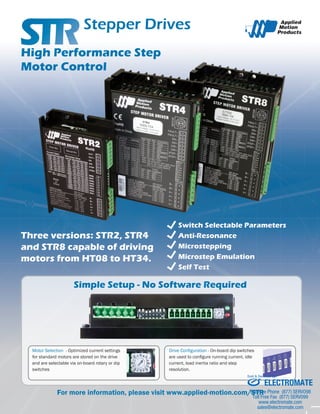
Three versions: STR2, STR4
and STR8 capable of driving
motors from HT08 to HT34.
Switch Selectable Parameters
Anti-Resonance
Microstepping
Microstep Emulation
Self Test
High Performance Step
Motor Control
Motor Selection - Optimized current settings
for standard motors are stored on the drive
and are selectable via on-board rotary or dip
switches
Drive Configuration - On-board dip switches
are used to configure running current, idle
current, load inertia ratio and step
resolution.
Simple Setup - No Software Required
ELECTROMATE
Toll Free Phone (877) SERVO98
Toll Free Fax (877) SERV099
www.electromate.com
sales@electromate.com
Sold & Serviced By:
2. Specifications
AMPLIFIER TYPE Dual H-bridge, 4 quadrant
CURRENT CONTROL STR2: 4 state PWM at 16 kHz
STR4/8: 4 state PWM at 20 kHz
OUTPUT CURRENT STR2: 0.3 - 2.2 A/phase (peak of sine)
STR4: 1.12 - 4.5 A/phase (peak of sine)
STR8: 2.35 - 8.0 A/phase (peak of sine)
POWER SUPPLY STR2: External 12 - 48 VDC power supply required
STR4: External 24 - 48 VDC power supply required
STR8: External 24 - 75 VDC power supply required
PROTECTION Over-voltage, under-voltage, motor/wiring shorts (phase-to-phase, phase-to-ground)
IDLE CURRENT 50% or 90% of running current, switch selectable
MODES OF OPERATION Step (pulse) & direction or CW/CCW pulse (pulse-pulse); selected via jumper under drive cover
STEP RESOLUTION Dip switch selectable resolution: 200, 200 SMOOTH, 400, 400 SMOOTH, 2000, 5000, 12800, or 20000 s/r
ANTI-RESONANCE
(Electronic Damping)
Raises the system damping ratio to eliminate midrange instability and allow stable operation throughout the speed
range and improves settling time.
Dip switch setting for range of load-to-motor inertia ratio.
SELF TEST Dip switch for automatically rotating step motor back and forth.
Useful for testing motor and power supply connections.
MICROSTEP EMULATION Performs high resolution stepping by synthesizing fine microsteps from coarse steps.
Available with full (200 SMOOTH) and half (400 SMOOTH) step resolutions.
STEP INPUT 5-24V, optically isolated, sinking (STR2) or differential (STR4/8). Minimum pulse width = 250 ns. Maximum pulse
frequency = 150 kHz or 2 MHz, user selectable. Function = step or CW pulse.
DIRECTION INPUT 5-24V, optically isolated, sinking (STR2) or differential (STR4/8). Minimum pulse width = 250 ns. Maximum pulse
frequency = 150 kHz or 2 MHz, user selectable. Function = direction or CCW pulse.
ENABLE INPUT 5-24V, optically isolated, sinking (STR2) or differential (STR4/8). Function = disable motor when closed.
FAULT OUTPUT 30V/80mA max, optically isolated, sinking or sourcing. Function = closes on drive fault.
DRIVE/MOTOR SETTINGS Motor select (select part number from pre-defined list): dip switches (STR2) or rotary switch (STR4/8)
Running current (100%, 90%, 80% or 70%): dip switches
Idle current (50% or 90%): dip switch
Load inertia ratio (0-4X or 5-10X): dip switch
Step size (resolution): dip switches
Step pulse type (step & direction or CW/CCW pulse): jumper under drive cover
Step pulse noise filter (150 kHz or 2 MHz): dip switch (STR2) or jumper under drive cover (STR4/8)
Self test (rotate motor back and forth): dip switch
DIMENSIONS STR2: 3.65 x 2.2 x 0.82 inches (not including mating connectors)
STR4/8: 4.65 x 2.97 x 1.3 inches (not including mating connectors)
WEIGHT STR2: 4.7 oz (including mating connectors)
STR4/8: 10.8 oz (including mating connectors)
OPERATING TEMPERATURE 0 to 85 ºC (32 - 185 ºF), interior of electronics section
AMBIENT TEMPERATURE 0 to 50 ºC (32 - 122 ºF), drive must be mounted to suitable heatsink
HUMIDITY 90% non-condensing
AGENCY APPROVALS RoHS
CE (EMC): EN 61800-3:2004
CE (LVD): EN 61800-5-1:2003
2
ELECTROMATE
Toll Free Phone (877) SERVO98
Toll Free Fax (877) SERV099
www.electromate.com
sales@electromate.com
Sold & Serviced By:
7. Step & Direction
MMI Control Option
3rd Party Controller
RS-232
RS-485/422 or CANopen
UP TO 32 AXES:
RS-485
MMI
Each drive connects
to a port on the hub.
or
UP TO
8
AXES
UP TO
4
AXES
RS-232 RS-232
HUB 444
1
2
3
4
# 5 Run/Stop (Toggle Switch)
Speed1/Speed2 (Toggle Switch)
Speed (Potentiometer)
Serial No
Error Codes
GR-Green
RD-RED
DRIVE OVER TEMP 1 GR + 3 RD
VOLTAGE HIGH 1 GR + 4 RD
VOLTAGE LOW 2 GR + 4 RD
OVER CURRENT 1 GR + 5 RD
COMM ERROR 1 GR + 7 RD
ST5-S
GND
B-B+
A-A+
V-V+
AN1
+5V
OUT+
OUT-EN-EN+
DIR-DIR+
STEP-STEP+
ID 5 ID 4 ID 3 ID 2 ID 1
Serial No
Error Codes GR-GreenRD-RED
POSITION LIMIT 1 GR + 1 RD
CCW LIMITTRIP 1 GR + 2 RD
CW LIMIT TRIP 2 GR + 2 RD
DRIVE OVER TEMP 1 GR + 3 RD
MOTOR OVER TEMP 2 GR + 3 RD
VOLTAGE HIGH 1 GR+ 4 RD
VOLTAGE LOW 2 GR + 4 RD
OVER CURRENT 1 GR + 5 RD
HALL FAIL 1 GR + 6RD
ENCODER FAIL 2 GR + 6 RD
COMM ERROR 1 GR + 7 RD
FrontView
XCOMMON
X7/CWLimit
X3/ServoEnable
X5
X4/AlarmReset
AnalogIN-AnalogIN+
X2/DIR-X2/
DIR+
X1/STEP/PWM+
X1/STEP/PWM-GND
GND
A+
A-B+
B-Z+
Z-
+5VOUT
YCOMMON
Y3/ALARM
Y2/INPOSN
Y1/BRAKE
18
17
16
15
14
13
12
11
10
9
8
7
6
5
4
2
3
1
19
20
21
22
23
24
25
redocnE
stuptuO
X6/CCWLimit
IN/OUT 1
ST5-Q
UP TO 128 AXES:
CANopen ▪▪ Step & direction
▪▪ CW & CCW pulse
Step motor systems have a natural tendency to resonate at certain speeds. The STR
drives automatically calculate the system’s natural frequency and apply damping to the
control algorithm. This greatly improves midrange stability, allows for higher speeds,
greater torque utilization, and improves settling times.
Anti-Resonance/Electronic Damping
Delivers better motor performance and higher speeds
Microstep Emulation
With Microstep Emulation, low resolution systems can still provide smooth motion. The drive
can take low-resolution step pulses and create fine resolution micro-step motion.
Delivers smoother motion in any application
1.8° Steps
Synthesized
Microsteps
Features
Applied Motion also offers two matched power supplies for use with the STR drives.
A 24VDC, 150W (part number PS150A24) and a 48VDC 320W version (part number
PS320A48). These power supplies have current overload capability making them ideal for
use with stepper drives.
The RC-050 regeneration clamp is for use where regeneration from the motor may cause
damage to the drive. In these cases the RC-050 is connected between the drive and
power supply and absorbs regenerated energy.
Accessories
#006BB3
#FFFFFF
#383838 85%k
76%C
68%M
67%Y
90%K
925-0002E 11/15/2012
Best value for step & direction applications
Power Supplies
RC-050 Regeneration Clamp
ELECTROMATE
Toll Free Phone (877) SERVO98
Toll Free Fax (877) SERV099
www.electromate.com
sales@electromate.com
Sold & Serviced By: