Harmonic Drive lightweight gear unit
•
0 recomendaciones•229 vistas

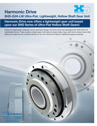
The document describes Harmonic Drive's SHD-2UH-LW series of lightweight hollow shaft gear units. These units feature a large hollow input shaft, robust cross roller bearing, and optimized lightweight design, making them more compact and up to 15% lighter than previous gear unit models. A table provides specifications such as size, gear ratio, torque, speed, weight, and part number for each unit in the series.

Recomendados
Más contenido relacionado
La actualidad más candente
La actualidad más candente (20)
Destacado
Destacado (17)
Similar a Harmonic Drive lightweight gear unit
Similar a Harmonic Drive lightweight gear unit (20)
Más de Electromate
Más de Electromate (20)
Último
Último (20)
Harmonic Drive lightweight gear unit
- 1. Harmonic Driveª SHD-2UH-LW Ultra-Flat, Lightweight, Hollow Shaft Gear Unit Harmonic Drive now offers a lightweight gear unit based upon our SHD Series of Ultra-Flat Hollow Shaft Gears! Using new lightweight materials and an optimized design Harmonic Drive has developed the SHD-2UH-LW Lightweight Series. These axially compact gear units feature a large hollow input shaft and a robust cross roller bearing so loads can be mounted directly to the unit without the need for additional support bearings. Sold & Serviced By: ELECTROMATE Toll Free Phone (877) SERVO98 Toll Free Fax (877) SERV099 www.electromate.com sales@electromate.com
- 2. Ordering Code Sold & Serviced By: SHD - 25 - 100 - 2UH - LW - SP Rating Table 50 100 50 100 50 100 160 50 100 160 50 100 160 50 100 160 Rated Torque at 2000 rpm 3.7 5.4 11 16 17 28 28 27 47 47 53 96 96 96 185 206 33 48 97 142 150 248 248 239 416 416 469 850 850 850 1,637 1,823 12 19 23 37 39 57 64 69 110 123 151 233 261 281 398 453 106 168 204 327 345 504 566 611 974 1,089 1,336 2,062 2,310 2,487 3,523 4,009 4.8 7.7 18 27 24 34 34 38 75 75 75 151 151 137 260 316 42 68 159 239 212 301 301 336 664 664 664 1,336 1,336 1,213 2,301 2,797 23 35 48 71 69 95 95 127 184 204 268 420 445 480 700 765 204 310 425 628 611 841 841 1,124 1,629 1,806 2,372 3,717 3,939 4,248 6,196 6,771 8,500 7,300 6,500 5,600 4,800 4,000 3,500 3,500 3,500 3,500 3,500 3,000 0.064 0.141 0.271 0.793 2.900 7.432 0.065 0.144 0.276 0.809 2.957 7.578 Size 14 17 20 25 32 40 Starting Torque 50 100 160 14 17 20 25 32 40 11 8.7 – 39 37 – 53 49 48 79 73 72 114 101 97 177 157 151 50 100 160 14 17 20 25 32 40 6.0 9.7 – 21 41 – 29 54 84 44 80 126 63 111 171 98 173 266 Nm lb-in Nm lb-in Nm lb-in Nm lb-in Grease Grease I x10ïkgm2 J x10ïkgfms2 2 1. Moment of Inertia: I =1/4GD2 2. Please refer to the CSD / SHD Catalog for an explanation of terms and technical information. Values shown below vary depending on the operating condition. Please use values as a reference. Backdriving Torque Max. Input Speed Max. Average Input Speed Moment of Inertia Limit for Repeated Peak Torque Limit for Average Torque Limit for Momentary Torque Gear Ratio Table 2-1 Table 2-2 Unit: Ncm Table 2-3 Unit: Nm Model Size Gear Ratio Type Lightweight Special SHD Series 14~40 50:1~160:1 2UH (Gearhead) (Custom Specification) leave blank for standard product Size Ratio Size Ratio ELECTROMATE Toll Free Phone (877) SERVO98 Toll Free Fax (877) SERV099 www.electromate.com sales@electromate.com
- 3. SHG/SHF-2UH Series SHD-2UH-LW Lightweight Weight Ratio x10-4rad arc min Sold Serviced By: 14 17 20 25 32 40 14 17 20 25 32 40 4.4 1.5 4.4 1.5 2.9 1.0 2.9 1.0 2.9 1.0 2.9 1.0 50 over 100 14 17 20 25 32 40 7.3 2.5 5.8 2.0 5.8 2.0 2.9 1.0 5.8 2.0 2.9 1.0 5.8 2.0 2.9 1.0 5.8 2.0 2.9 1.0 5.8 2.0 2.9 1.0 x10⁻⁴rad arc min x10-4rad arc min 0.71 0.49 69% 1 0.66 66% 1.38 0.84 61% 2.1 1.4 67% 4.5 2.7 60% 7.7 4.6 60% 3 SHG/SHF Series Gear Unit SHD Series Gear Unit About 15% Shorter Weight Comparison Accuracy Hysteresis Loss Table 3-1 Unit: Kg Size Ratio Table 3-2 Size Table 3-3 Size Ratio ELECTROMATE Toll Free Phone (877) SERVO98 Toll Free Fax (877) SERV099 www.electromate.com sales@electromate.com
- 4. Sold Serviced By: 50 160 14 17 20 25 32 40 50 +1.0 +1.6 +2.4 +4.0 +7.7 +13 — — — -0.7 -1.2 -2.4 -3.9 ー No-load running torque is the input torque (high speed shaft) which is required to rotate the Harmonic Drive™ gear with no load applied to the output. 10000 1000 100 10 Harmonic grease SK-2 Recommended quantity Size Size 1 -10 0 10 20 30 40 10000 1000 100 10 Table 4-2 Unit: Ncm 1 -10 0 10 20 30 40 10000 1000 100 10 1 -10 0 10 20 30 40 10000 1000 100 10 1 -10 0 10 20 30 40 40 32 25 20 17 14 40 32 25 20 17 14 40 32 25 20 17 14 40 32 25 20 17 14 No Load Running Torque Compensation Value for Each Ratio Ratio: 100 Ratio Size Table 4-1 Graph 4-1 Graph 4-2 Graph 4-3 Graph 4-4 Measurement condition Lubricant Grease Name Grease quantity Harmonic grease SK-1A Torque value is measured after 2 hour run-in at 2000 rpm input. Please contact HDLLC if you are using oil lubricant. The no load running torque of Harmonic Drive gears varies with the gear ratio. The graphs below indicate a value for ratio 100. For other gear ratios, add the compensation value from table 4-2. 4 No Load Running Torque for Ratio 100 Input Speed 500r/min Input Speed 1000r/min Ambient Temperature (C°) Ambient Temperature (C°) Size Size No Load Running Torque (Ncm) No Load Running Torque (Ncm) Input Speed 2000r/min Input Speed 3500r/min Ambient Temperature (C°) Ambient Temperature (C°) No Load Running Torque (Ncm) No Load Running Torque (Ncm) ELECTROMATE Toll Free Phone (877) SERVO98 Toll Free Fax (877) SERV099 www.electromate.com sales@electromate.com
- 5. Based on recommended tolerance Efficiency at Rated Torque (Size 14) 100% 90% 80% 70% 60% 50% 40% 30% 20% 10% 0% -10 0 10 20 30 40 Ratio 100 Ratio 160 100% 90% 80% 70% 60% 50% 40% 30% 20% 10% 0% -10 0 10 20 30 40 100% 90% 80% 70% 60% 50% 40% 30% 20% 10% 0% -10 0 10 20 30 40 100% 90% 80% 70% 60% 50% 40% 30% 20% 10% 0% -10 0 10 20 30 40 100% 90% 80% 70% 60% 50% 40% 30% 20% 10% 0% Sold Serviced By: ELECTROMATE Toll Free Phone (877) SERVO98 Toll Free Fax (877) SERV099 www.electromate.com sales@electromate.com -10 0 10 20 30 40 1.0 0.9 0.8 0.7 0.6 0.5 0.4 0.3 0.2 0.1 0.0 0.1 0.2 0.3 0.4 0.5 0.6 0.7 0.8 0.9 1.0 Measurement condition Table 4-1 Installation Load torque Rated torque Lubricant Grease Name Grease quantity Harmonic grease SK-1A Harmonic grease SK-2 Recommended quantity The scale on the graph is off relative to the lines drawn on the graph Efficiency The gear efficiency is affected by many factors. Efficiency depends on the gear ratio, input speed, load torque, temperature, quantity of lubricant and type of lubricant. Efficiency values shown in the tables shown below are for rated torque. If the actual load torque is below rated torque, a compensation factor must be used. 3VHK;VYXL™9H[LK;VYXL!,MMPJPLUJ`$,MMPJPLUJ`MYVT.YHWO 5-2 thru 5-6. 3VHK;VYXL#9H[LK;VYXL!,MMPJPLUJ`$,MMPJPLUJ`MYVT.YHWO [OY_*VTWLUZH[PVU*VLMMPJPLU[MYVT.YHWO Efficiency at Rated Torque (Sizes 17, 20, 25, 32, 40) 500r/min 1000r/min 2000r/min 3500r/min 500r/min 1000r/min 2000r/min 3500r/min 500r/min 1000r/min 2000r/min 3500r/min 500r/min 1000r/min 2000r/min 3500r/min 500r/min 1000r/min 2000r/min 3500r/min 500r/min 1000r/min 2000r/min 3500r/min 5 Ratio 30 Ambient Temperature (C°) Efficiency (%) Ratio 100 Ratio 50 Ambient Temperature (C°) Efficiency (%) Ambient Temperature (C°) Efficiency (%) Ambient Temperature (C°) Efficiency (%) Ambient Temperature (C°) Efficiency (%) Graph 5-1 Graph 5-2 Graph 5-3 Graph 5-4 Graph 5-5 Graph 5-6
- 6. G JI H L T-φU b e c d a M N φB φA h7 φF H7 φE h7 φD h7 (O) φF H7 φC h7 φS Q-R φP 3-M3 W-X φV K Z P φY φA h7 φB φC h7 φD h7 φE h7 φF H7 GHIJKLMNO φP(P) QR φS T φU φV W X φY Zabcde Weight (kg) Sold Serviced By: 14 17 20 25 32 40 70 52 36 74 20 14 45.5 12 19.5 14 6.5 97 6.5 16.6 (2.5) 3 M3 64 8 3.5 43 8 M3×5 φ3.5×5.5 36 5.5 6804ZZ 6804ZZ D49585 S20304.5 S20304.5 0.49 80 62 45 84 25 19 48 12 20.5 15.5 6.5 10 87 18 (2.5) 3 M3 74 12 3.5 52 12 M3×6 φ3.5×6.5 45 5.5 6805ZZ 6805ZZ D59685 S25356 S25356 0.66 90 73 50 95 30 21 42 5 21.5 15.5 ー 10.5 87 17.5 25.5 6 M3×6 84 12 3.5 61.4 12 M3×6 φ3.5×6.5 ーー 6806ZZ 6806ZZ D69785 S30405 S30405 0.84 110 87 60 115 38 29 46.5 6 24 16.5 ー 10.5 10 6 20.6 33.5 6 M3×6 102 12 4.5 76 12 M4×7 φ4.5×8.5 ーー 6808ZZ 6808ZZ D84945 S38475 S38475 1.4 142 114 75 147 54 41 55 7 28.6 19.4 ー 12 11 7.5 24.9 48 6 M3×6 132 12 5.5 99 12 M5×8 φ5.5×7.6 ーー 6811ZZ 6810ZZ D1101226 S54645 S50605 2.7 170 137 100 175 64 51 65 8 33 24 ー 14 14 9 29.5 57 6 M4×8 158 12 6.6 120 16 M6×10 φ6.6×10 ーー 6813ZZ 6813ZZ D1321467 S64745 S64745 4.6 6 External Dimensions Dimension Table Output Flange Input Shaft Size 14, 17 Input Configuration Table 6-1 Size Symbol ELECTROMATE Toll Free Phone (877) SERVO98 Toll Free Fax (877) SERV099 www.electromate.com sales@electromate.com
- 7. Specification for Crossroller Bearing Sold Serviced By: ELECTROMATE Toll Free Phone (877) SERVO98 Toll Free Fax (877) SERV099 www.electromate.com sales@electromate.com Table 7-1 Pitch Circle Offset Basic Dynamic Load Rating Basic Static Load Rating Moment Stiffness dp R C Co Allowable Moment Load Mc Nm lb-in Km ×104Nm/rad ×104lb-in/rad Size * The moment stiffnesses are mean values. Installation and Transmission Torque Table 7-2 Size 14 17 20 25 32 40 8 M3 64 2.0 18 108 956 12 M3 74 2.0 18 186 956 12 M3 84 2.0 18 210 1,823 12 M4 102 4.5 40 431 3,815 12 M5 132 9.0 80 892 7,895 12 M6 158 15.3 135 1.509 13,356 14 17 20 25 32 40 0.0503 0.061 0.070 0.086 0.112 0.133 0.0111 0.0115 0.011 0.0121 0.0173 0.0195 29 52 73 109 191 216 652 1,169 1,641 2,450 4,294 4,856 43 81 110 179 327 408 967 1,821 2,473 4,024 7,351 9,172 m m ×102N lb ×102N lb 37 62 93 129 290 424 327 549 823 1,142 2,567 3,753 7.08 12.7 21 31 82.1 145 63 112 186 274 727 1,283 Number of screws Size of screws Pitch Circle Diameter mm Screw Tightening Torque Torque Transmitting Capacity Nm lb-in Nm lb-in Table 7-3 Size 14 17 20 25 32 40 8 M3 43 4.5 2.0 18 72 637 12 M3 52 4.5 2.0 18 130 1,151 12 M3 61.4 4.5 2.0 18 154 1,363 12 M4 76 6 4.5 40 321 2,841 12 M5 99 8 9.0 80 668 5,912 12 M6 120 9 15.3 135 1,148 10,161 7 A B Bolt connection to housing and resulting transmission torque A Bolt connection to output flange and resulting transmission torque B Number of screws Size of screws Pitch Circle Diameter mm Effective Thread Depth Screw Tightening Torque Torque Transmitting Capacity Nm lb-in Nm lb-in 1. Recommended bolt : JIS B 1176 socket head cap screw strength range : JIS B 1051 over 12.9 2. Torque coefficient : K=0.2 3. Clamp coefficient A=1.4 4. Coefficient of friction: 0.15 5. Strict compliance to the recommended screw tightening torques is especially important for the lightweight aluminum housing flange. Exceeding the recommended values (over tightening) can cause deformation of the housing flange under the bolt heads. This will result in the housing slipping under full torque loads. Flat washers should be used for all screws in direct contact with the aluminum housing. (Please contact a Sales Engineer for more information.)
- 8. Input Shaft Load Limits Sold Serviced By: The Hollow Shaft Unit type is supported by two deep groove single row ball bearings. To achieve peak performance, it is essential to confirm that the actual load applied to input shaft does not exceed the limits specified below. Figure 8-1 shows the points of application of forces, which determine the Maximum Allowable Radial and Axial Loads as indicated in Graph 8-1. The maximum values, as given Graph 8-1 are valid for and average input speed of 2,000 rpm and a mean bearing life of L10=7,000h. Example: If the hollow shaft of a SHD-40-2UH-LW unit is subjected to an axial load of 400 N, the maximum allowable radial force will be 275 N. Bearing Specification for Input Side Bearing A Bearing B a Fr Fa a b 179 191 199 290 410 602 20.0 19.5 17.5 21.0 26.0 33.5 16.5 18.0 15.5 16.5 19.5 20.5 2,470 3,150 3,650 5,550 6,200 12,100 4,000 4,500 4,700 6,350 6,400 11,900 Size Bearing Model Bearing Model 6804ZZ 6805ZZ 6806ZZ 6808ZZ 6810ZZ 6813ZZ 2,470 3,150 3,650 5,550 8,500 12,100 4,000 4,500 4,700 6,350 8,800 11,900 6804ZZ 6805ZZ 6806ZZ 6808ZZ 6811ZZ 6813ZZ C(r N) Co(r N) Cr(N) Cor(N) (mm) (mm) Fr(N) 14 17 20 25 32 40 Bearing A Bearing B 14 17 20 25 32 40 SHD-2UH-LW Input Shaft Load Limit Axial Load Fa (N) Fa : Axial Load (N) Fr : Radial Load (N) Radial Load Fr (N) Table 8-1 Graph 8-1 Figure 8-1 Basic Dynamic Load Rating Basic Static Load Rating Basic Dynamic Load Rating Basic Static Load Rating Overhung Distance b Distance between Bearings Max. Radial Load 700 600 500 400 300 200 100 0 0 100 200 300 400 500 600 700 ELECTROMATE Toll Free Phone (877) SERVO98 Toll Free Fax (877) SERV099 www.electromate.com sales@electromate.com