
![ROBO Cylinder®
*1 Connect the power & I/O cable.
Refer to P. 36 for details on this cable.
SE: Stroke End
ME: Mechanical End
*2 The slider moves to the ME during
home return, so pay attention to possible
contact with surrounding structures.
*3 Reference position is used when
calculating the Ma and Mc moments.
Teaching port
Cable joint
connector *1
27.2
External view of the brake specication
18 ERC3-SA5C
4-M4 depth 8
5 41 5
(Pitch of reamed
holes( ±0.02)
26 51 15
3
Stroke
3
142.5
L
F
ME SE SE ME*2
Reference plane
47
50
55.3
68.7
50
57
X
20.5 20.5
G-M4 depth 7 D×100P
(from the bottom of the base)
C×100P 50 20
B (reamed hole and oblong hole pitch)
2-ø4, H7 depth 5.5
A 44 143
26
24
H-ø4.5, through ø8 counterbored,
depth 4.5 (from the opposite side)
J-Oblong hole, depth 5.5
(from the bottom of the base)
Y
5
4
Detail Y
185
ø4.5
ø8
3 4.5
5
Detail view of X
(Mounting hole and
the reference plane)
2-ø4, H7 depth 6
50
+0.012
0
O‘set reference position
for Ma/Mc moments *3
36.5
* The overall length of the brake speci–cation
is 42.5 mm longer than the standard speci–cation
and its mass is 0.4 kg heavier.
48.1
Actuator specificaton Dimensions and Mass by Stroke
Item Description
Drive system Ball screw ø10 mm, rolled C10
Positioning repeatability (*1) ± 0.02 mm [± 0.03 mm]
Lost motion 0.1 mm or less
Static allowable load moment Ma: 29.4 N•m, Mb: 42.0 N•m, Mc: 60.5 N•m
Dynamic allowable load moment (*2) Ma: 7.1 N•m, Mb: 10.2 N•m, Mc: 14.7 N•m
Overhang load lengths 150 mm or less in Ma directions, 150 mm or less
in Mb and Mc directions
Ambient operating temperature,
humidity 0 to 40˚C, 85% RH or less (Non-condensing)
(*1) The specification in [ ] applies when the lead is 20 mm.
(*2) Based on 5,000 km of traveling life
Allowable load moment directions Overhang load lengths
Controllers (Built into the Actuator)
②I/O type
With the ERC3 series, one of the following five types of built-in controllers can be selected depending on the external input/output (I/O) type. Select the type that meets your purpose.
Name External view Model number Features
Maximum number
of positioning
points
Input
power
Power supply
capacity
Standard
price
Reference
page
PIO type (NPN
specification) ERC3-SA5C-I-42P---NP--
Simple control type
accommodating up to 16
positioning points
16
DC24V
High-output
setting
enabled:
3.5A rated
4.2A max.
High-output
setting
disabled:
2A
— P27
PIO type (PNP
specification) ERC3-SA5C-I-42P---PN-- PNP I/O type 16
SIO type ERC3-SA5C-I-42P---SE--
High-function type
accommodating up to
512 positioning points
(PIO converter is used)
512
Pulse-train
type (NPN
specification)
ERC3-SA5C-I-42P---PLN--
Pulse-train input type
supporting the NPN
specification
−
Pulse-train
type (PNP
specification)
ERC3-SA5C-I-42P---PLP--
Pulse-train input type
supporting the PNP
specification
−
L
L
Ma Mb Mc Ma Mc
Stroke 50 100 150 200 250 300 350 400 450 500 550 600 650 700 750 800
L 284.5 334.5 384.5 434.5 484.5 534.5 584.5 634.5 684.5 734.5 784.5 834.5 884.5 934.5 984.5 1034.5
A 73 100 100 200 200 300 300 400 400 500 500 600 600 700 700 800
B 0 85 85 185 185 285 285 385 385 485 485 585 585 685 685 785
C 0 0 1 1 2 2 3 3 4 4 5 5 6 6 7 7
D 0 0 0 1 1 2 2 3 3 4 4 5 5 6 6 7
F 142 192 242 292 342 392 442 492 542 592 642 692 742 792 842 892
G 4 4 4 6 6 8 8 10 10 12 12 14 14 16 16 18
H 4 4 6 6 8 8 10 10 12 12 14 14 16 16 18 18
J 0 1 1 1 1 1 1 1 1 1 1 1 1 1 1 1
Mass (kg) 1.4 1.5 1.6 1.7 1.9 2.0 2.1 2.2 2.3 2.4 2.5 2.7 2.8 2.9 3.0 3.1
Dimensional Drawings
* If the non-motor side (NM) specification is selected, the dimension on the motor side
(the distance to the home from ME) and that on the front side are flipped.
Sold Serviced By:
ELECTROMATE
Toll Free Phone (877) SERVO98
Toll Free Fax (877) SERV099
www.electromate.com
sales@electromate.com](data:image/gif;base64,R0lGODlhAQABAIAAAAAAAP///yH5BAEAAAAALAAAAAABAAEAAAIBRAA7)
Recomendados
Más contenido relacionado
La actualidad más candente
La actualidad más candente (20)
Destacado
Destacado (20)
Similar a Iai erc3 sa5_c_specsheet
Similar a Iai erc3 sa5_c_specsheet (18)
Más de Electromate
Más de Electromate (20)
Último
Último (20)
Iai erc3 sa5_c_specsheet
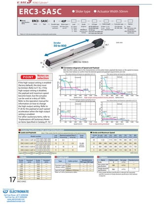
- 1. 25 20 15 10 25 20 15 10 18 50 POINT Notes on selection Actuator Specifications (High-output Setting Enabled) 14 12 10 8 6 4 Vertical 600 800 1000 1200 1400 0 200 400 600 800 1000 1200 1400 High-output setting enabled (Factory default) 14 12 10 8 6 4 Vertical 3 600 800 1000 1200 1400 0 200 400 600 800 1000 1200 1400 Leads and Payloads (Note 1) Take caution that the maximum payload decreases as the speed increases. Legend ➀ Stroke ➁ I/O type ➂ Cable length ➃ Option (Unit: mm/s) 17 ERC3-SA5C ROBO Cylinder® Model number Lead (mm) Maximum payload (Note 1) Stroke Horizontal (kg) Vertical (kg) (mm) ERC3-SA5C-I-42P-20- ➀ - ➁ - ➂ - ➃ 20 6.5 1 50~800 (every 50 mm) ERC3-SA5C-I-42P-12- ➀ - ➁ - ➂ - ➃ 12 9 2.5 ERC3-SA5C-I-42P-6- ➀ - ➁ - ➂ - ➃ 6 18 6 ERC3-SA5C-I-42P-3- ➀ - ➁ - ➂ - ➃ 3 20 12 ①Stroke ③Cable length ④Options *Refer to P. 36 for maintenance cables. (*) If the simple absolute specification is selected, the separately sold PIO converter of simple absolute specification (with battery) is required. Stroke Lead 50~450 (every 50mm) 500 (mm) 550 (mm) 600 (mm) 650 (mm) 700 (mm) 750 (mm) 800 (mm) 20 1120 1115 935 795 680 585 510 12 900 805 665 560 475 405 350 300 6 450 400 330 280 235 200 175 150 3 225 200 165 140 115 100 85 75 Type Cable symbol Standard price PIO type SIO type Standard type (Robot cable) P (1m) — — S (3m) — — M (5m) — — Special length X06(6m)~X10(10m) — — Payload (kg) 0 0 200 400 Speed (mm/s) 5 Payload (kg) 0 Speed (mm/s) 2 Payload (kg) 0 0 200 400 Speed (mm/s) 5 Payload (kg) 0 Speed (mm/s) 2 Lead 3 LLeeaadd 66 LLeeaadd 1122 LLeeaadd 2200 LLeeaadd 66 LLeeaadd 1122 LLeeaadd 2200 Horizontal 5 7 9 6.5 LLeeaadd 33 2.5 0.5 0.5 0.5 5.5 1 Lead 3 LLeeaadd 66 LLeeaadd 1122 LLeeaadd 2200 LLeeaadd 66 LLeeaadd 1122 LLeeaadd 2200 Horizontal 2 12 6 3.5 LLeeaadd 33 1.5 2.5 1 1 0.5 1 The values below are based on operation at 0.3 G. The values below are based on operation at 0.2 G. The values below are based on operation at 0.3 G. The values below are based on operation at 0.2 G for lead 3 and 0.3 G for all other leads. High-output setting disabled 50 68.7 284.5 to 1034.5 Stroke 50 to 800 Unit: mm Stroke and Maximum Speed Stroke (mm) Standard price 450 — 500 — 550 — 600 — 650 — 700 — 750 — 800 — Stroke (mm) Standard price 50 — 100 — 150 — 200 — 250 — 300 — 350 — 400 — Correlation diagrams of Speed and Payload With the ERC3 series, due to the characteristics of the pulse motor, payload decreases as the speed increases. Use the chart below to confirm that the desired speed and payload requirements are met. Name Option code See page Standard price Brake B P15 — Non-motor side specification NM P15 — Simple absolute specification ABU P15 — (*) ERC3-SA5C Model Specification Items ERC3 Series SA5C Type 42P Motor type Lead Stroke I/O type Cable length Option I Encoder type 42P: Pulse motor, size 42 I: Incremental specification NP: PIO (NPN) type PN: PIO (PNP) type SE: SIO type PLN: Pulse-train (NPN) type PLP: Pulse-train (PNP) type CN: CON type MC: MEC type 20 : 20mm 12 : 12mm 6 : 6mm 3 : 3mm *Refer to P. 14 for the description of items constituting the model number. Slider type Actuator Width 50mm 50:50mm 800:800mm (Can be set in 50-mm increments) B : Brake NM : Non-motor side specification ABU: Simple absolute specification N: None P: 1m S: 3 m M: 5m X: Specified length Controller type If the high-output setting is enabled (factory default), the duty must be limited. (Refer to P. 16.) If the high-output setting is disabled, the payload and maximum speed become lower, but the actuator can be used at a duty of 100%. Refer to the operation manual for information on how to change the high-output setting. Refer to P. 26 for the payload at each speed/ acceleration when the high-output setting is enabled. For other cautionary items, refer to "Explanations of/Cautionary Notes on Items Specified in Catalog (P. 15)." Sold & Serviced By: ELECTROMATE Toll Free Phone (877) SERVO98 Toll Free Fax (877) SERV099 www.electromate.com sales@electromate.com
- 2. ROBO Cylinder® *1 Connect the power & I/O cable. Refer to P. 36 for details on this cable. SE: Stroke End ME: Mechanical End *2 The slider moves to the ME during home return, so pay attention to possible contact with surrounding structures. *3 Reference position is used when calculating the Ma and Mc moments. Teaching port Cable joint connector *1 27.2 External view of the brake specication 18 ERC3-SA5C 4-M4 depth 8 5 41 5 (Pitch of reamed holes( ±0.02) 26 51 15 3 Stroke 3 142.5 L F ME SE SE ME*2 Reference plane 47 50 55.3 68.7 50 57 X 20.5 20.5 G-M4 depth 7 D×100P (from the bottom of the base) C×100P 50 20 B (reamed hole and oblong hole pitch) 2-ø4, H7 depth 5.5 A 44 143 26 24 H-ø4.5, through ø8 counterbored, depth 4.5 (from the opposite side) J-Oblong hole, depth 5.5 (from the bottom of the base) Y 5 4 Detail Y 185 ø4.5 ø8 3 4.5 5 Detail view of X (Mounting hole and the reference plane) 2-ø4, H7 depth 6 50 +0.012 0 O‘set reference position for Ma/Mc moments *3 36.5 * The overall length of the brake speci–cation is 42.5 mm longer than the standard speci–cation and its mass is 0.4 kg heavier. 48.1 Actuator specificaton Dimensions and Mass by Stroke Item Description Drive system Ball screw ø10 mm, rolled C10 Positioning repeatability (*1) ± 0.02 mm [± 0.03 mm] Lost motion 0.1 mm or less Static allowable load moment Ma: 29.4 N•m, Mb: 42.0 N•m, Mc: 60.5 N•m Dynamic allowable load moment (*2) Ma: 7.1 N•m, Mb: 10.2 N•m, Mc: 14.7 N•m Overhang load lengths 150 mm or less in Ma directions, 150 mm or less in Mb and Mc directions Ambient operating temperature, humidity 0 to 40˚C, 85% RH or less (Non-condensing) (*1) The specification in [ ] applies when the lead is 20 mm. (*2) Based on 5,000 km of traveling life Allowable load moment directions Overhang load lengths Controllers (Built into the Actuator) ②I/O type With the ERC3 series, one of the following five types of built-in controllers can be selected depending on the external input/output (I/O) type. Select the type that meets your purpose. Name External view Model number Features Maximum number of positioning points Input power Power supply capacity Standard price Reference page PIO type (NPN specification) ERC3-SA5C-I-42P---NP-- Simple control type accommodating up to 16 positioning points 16 DC24V High-output setting enabled: 3.5A rated 4.2A max. High-output setting disabled: 2A — P27 PIO type (PNP specification) ERC3-SA5C-I-42P---PN-- PNP I/O type 16 SIO type ERC3-SA5C-I-42P---SE-- High-function type accommodating up to 512 positioning points (PIO converter is used) 512 Pulse-train type (NPN specification) ERC3-SA5C-I-42P---PLN-- Pulse-train input type supporting the NPN specification − Pulse-train type (PNP specification) ERC3-SA5C-I-42P---PLP-- Pulse-train input type supporting the PNP specification − L L Ma Mb Mc Ma Mc Stroke 50 100 150 200 250 300 350 400 450 500 550 600 650 700 750 800 L 284.5 334.5 384.5 434.5 484.5 534.5 584.5 634.5 684.5 734.5 784.5 834.5 884.5 934.5 984.5 1034.5 A 73 100 100 200 200 300 300 400 400 500 500 600 600 700 700 800 B 0 85 85 185 185 285 285 385 385 485 485 585 585 685 685 785 C 0 0 1 1 2 2 3 3 4 4 5 5 6 6 7 7 D 0 0 0 1 1 2 2 3 3 4 4 5 5 6 6 7 F 142 192 242 292 342 392 442 492 542 592 642 692 742 792 842 892 G 4 4 4 6 6 8 8 10 10 12 12 14 14 16 16 18 H 4 4 6 6 8 8 10 10 12 12 14 14 16 16 18 18 J 0 1 1 1 1 1 1 1 1 1 1 1 1 1 1 1 Mass (kg) 1.4 1.5 1.6 1.7 1.9 2.0 2.1 2.2 2.3 2.4 2.5 2.7 2.8 2.9 3.0 3.1 Dimensional Drawings * If the non-motor side (NM) specification is selected, the dimension on the motor side (the distance to the home from ME) and that on the front side are flipped. Sold Serviced By: ELECTROMATE Toll Free Phone (877) SERVO98 Toll Free Fax (877) SERV099 www.electromate.com sales@electromate.com