SlideShare una empresa de Scribd logo
1 de 16
ROBOTIC CAR KIT
ECET 365 EMBEDDED MICROPROCESSOR W/LAB
OCTOBER 13, 2016
By Elijah Barner, Timothy Moore, Bryan Quiroz
TABLE of CONTENT
Introductions Pg. 3
Block Diagram Pg. 4-5
Components Pg. 6
Getting Started Pg. 7-9
Robot Code Pg. 10-12
Troubleshooting Tips Pg. 13
Caution Pg. 14
Contact Information/Technical Support Pg. 15
References Pg. 16
INTRODUCTION
Welcome to the ECET Robotic Car Kit. The following kit contain parts for TWR-
S12G128 microcontroller tower, SRK + Line kit, and all the associated wires, and connectors to
operate the automated robot. This specific model follows a black strip line race track based on
the users design. This manual contain information for assembly, troubleshooting tips, schematic
diagrams, coding information and software. It also contains contact information for customer
service at the end of the manual.
Code Block Diagram
System Block Diagram
Power Supply Subsystems
18650 Lithium Ion Batteries
● Typical Capacity: 3000 mAh
● Min Capacity: 2900 mAh
● Nominal Voltage: 3.7V
● Charging Voltage: 4.35V
12 volt regulator - 7812
● Max Amperage output:1 amp
5 volt regulator - 7805
● Max Amperage output:1 amp
5V To 3.3V DC-DC Step-Down Power Supply Buck Module
● Operating Supply Voltage: 4.2 V to 10 V
● Output Current: 800mA
● Output Voltage: 3.3 V
Motor Subsystems
SN754410NE - H Bridge
● Operating Supply Voltage: 4.5 V to 36 V
● Output Current: 1100 mA
Digilent 12v motor
● Max Operating Supply Voltage: 12 V
● Output Current: 240 mA
● Torque: 617 g-cm
Sensor Subsystems
OPB704
● Max Collector Current:25 mA
● Vf - Forward Voltage: 1.7 V
GETTING STARTED
Chassis assembly requires a fillister head screwdriver, needle nose pliers, wire strippers, and the
associated mounts with-in the kit.
Attach the four sensor with the double sided Velcro strips in the front of the chassis.
Attach the microcontroller TWR-12SG128 to the robots chassis via tie-raps or use the extra
bracket with screws.
Power Supply assembly for +5V (7805CT) voltage regulator.
This how the robot will look when it has finally been assembled.
Robot Code
//sensor 1 pp0 pin A40 black
//sensor 2 pp1 pin A39 red
//sensor 3 pp2 pin A38 white
//sensor 1 pp0 pin A40 black
//sensor 2 pp1 pin A39 red
//sensor 3 pp2 pin A38 white
//sensor 4 pp3 pin A37 yellow
//sensor layouton thesensor board1,4,2,3(tied intight notmoving them)
#include <hidef.h> /* common defines and macros */
#include "derivative.h" /* derivative-specificdefinitions */
int speed =150;
int delayspeed=5;
int decrease=25;
//function protypes
void delay(unsigned int);//delay
void test(void); //test
void init_PWM01(void); //motor
void init_isr(void); //sensor
void forward(void); //move forward
//void reverse(void);
void left(void);
void right(void);
void stop(void);
char sensor;
char duty;
void main(void)
{
test(); //initializetest
init_PWM01(); //initializemotor
init_isr(); //initialize sensors
for(;;)
{
delay(speed);
} //end for(;;)
} //endmain
void test(void)
{
DDRT=0XFF;
DDRP|=0xF0;
}
void delay(unsigned del) {
unsignedinti,j;
for (i=0; i<del;i++) {
for (j=0; j<2000; j++) {
asm("nop")}};
}
void init_PWM01(){
PWMCLK &=~0X30; //Chooseclock a for pwm4andpwm5
PWMCLKAB &=~0X30; //Chooseclocka for pwm4 andpwm5
PWMPRCLK =0x04; // clock dividedby 2^4
//PWMSCLA=3;
PWMPOL|=0X30;
PWMPER4=195;
PWMPER5=195;
PWME|=0X30; //Enable pwmchannels 4 and 5 onthetower
PWMDTY4=0; //Right
PWMDTY5=0; //Left
}
void forward(){
PWMDTY4=speed;
PWMDTY5=speed;
PTT=0x90;
}
void stop(){
PWMDTY4=0;
PWMDTY5=0;
PTT=0x90;
}
void left(){
PWMDTY4=(speed-decrease);
PWMDTY5=(speed/5); //slow down
PTT=0x40;
}
void right(){
PWMDTY4=(speed/5); //slow down
PWMDTY5=(speed-decrease);
PTT=0x80;
}
void init_isr()//usePP7:PP4
{
DDRP &=~0x0F; //use pp0,pp1,pp2,pp3interrupt pins.
PPSP &=~0x0F;//choosepulldown
PERP |=0x0F;//enablepull
PIEP |=0x0F;//enablelocal leveenable
asm(cli); // enableglobal levelenable
PIFP |=0x0F;// clear allflags on pp0,pp1,pp2,pp3
}
//define ISR
#pragma CODE_SEG NON_BANKED
interrupt((0x10000-0xFF8E)/2-1)
void PortP_isr(void)
{
if ((PIFP&0x02)==0x02) // sensor 2 has gonefrom0 to 1
{
left();
delay(delayspeed);
PIFP|=0x02; // clearflag
}
if ((PIFP&0x01)==0x01) // sensor 1 has gonefrom0 to 1
{
right();
delay(delayspeed);
PIFP|=0x01; // clearflag
}//
if ((PIFP&0x04)==0x04) // sensor 3 has gonefrom0 to 1
{
forward(); //good
delay(delayspeed*2);
PIFP|=0x04; // clearflag
}
if ((PIFP&0x08)==0x08) // sensor 4 has gonefrom0 to 1
{
forward();
delay(delayspeed*2);
PIFP|=0x08; // clearflag
}
}
#pragma CODE_SEG DEFAULT
TROUBLESHOOTING TIPS
Tip#1:
Check to see if both the +5V and 12V regulator output voltages are correct. They supply both
voltage to the microcontroller, H-bridge, motors, and sensors. Depending on the model you have
some of our robots contain P-mod H-bridge circuits that require an addition two wires. The
supply voltages are 5V for the microcontroller and motors. Then 3.3 to 5V for each sensor.
Tip#2:
Sometimes there will be a message stating that the microcontroller has not been detected by PC.
First check to see if you download the latest version of CodeWarrior 5.1 are above with the latest
devices driver.
Tip#3:
The code associate with the robot is preload on the robot. If there is any issues with the code a
copy of the program can be found for troubleshooting purpose. It is located at the end of the user
manual. (Warning! CodeWarrior IDE interface is case sensitive if any of the code has not been
properly type it will result in an error. The code will not compile neither will it upload to the
microcontroller.)
Tip#4:
If and of the hardware is defective please contact us immediately so we can send you any
replacement parts. The replacement parts included that are PSU battery compartment, motors, H-
bridge, and robot chassis. (If you notice any of the chassis, or electronic hardware missing you
should contact us with a brief description of the part and the serial number/ID number located on
the part.)
Make sure that all of the robot wiring and associated components are properly placed and
configure. Because if anything is not properly placed it could lead to possible shortage or
possible damage to electronic components. Also check to make sure that the power supply
system wiring is placed correctly due to possible fire hazard.
CONTACT INFORMATION/TECH
SUPPORT
If you have any issues regarding the software and hardware please contact us at
ebarner777@gmail.com for customer support.
If you need to contact our other branches please email us at tim_thegreenbeast@yahoo.comor
b_quiroz@live.com.
References
http://www.mouser.com/ProductDetail/Optek-TT-
Electronics/OPB704/?qs=4w61lb%2FlP8DOAlCIZ3m0tQ%3D%3D
https://www.sparkfun.com/datasheets/Components/LM7805.pdf
http://pdf.datasheetcatalog.com/datasheet/analogdevices/AD7812YN.pdf
https://www.powerstream.com/p/LG-ICR18650HE2-REV0.pdf
https://reference.digilentinc.com/chipkit_pro_mx4/mrk_line
http://www.ti.com/lit/ds/symlink/sn754410.pdf

Más contenido relacionado

La actualidad más candente

IRJET- Bluetooth Controlled Metal Detecting Robot with Message Alert
IRJET- Bluetooth Controlled Metal Detecting Robot with Message AlertIRJET- Bluetooth Controlled Metal Detecting Robot with Message Alert
IRJET- Bluetooth Controlled Metal Detecting Robot with Message AlertIRJET Journal
 
Básicos de Functional Test Systems - Testing Days Tijuana
Básicos de Functional Test Systems - Testing Days TijuanaBásicos de Functional Test Systems - Testing Days Tijuana
Básicos de Functional Test Systems - Testing Days TijuanaInterlatin
 
Robotic Car Controlled over Bluetooth with Obstacle Avoidance
Robotic Car Controlled over Bluetooth with Obstacle AvoidanceRobotic Car Controlled over Bluetooth with Obstacle Avoidance
Robotic Car Controlled over Bluetooth with Obstacle Avoidancekiet group of institution
 
Migration ux to windows - ICT i3070
Migration ux to windows - ICT i3070Migration ux to windows - ICT i3070
Migration ux to windows - ICT i3070Interlatin
 
Functional Test Systems - Testing Days Bajío
Functional Test Systems - Testing Days BajíoFunctional Test Systems - Testing Days Bajío
Functional Test Systems - Testing Days BajíoInterlatin
 
PowerMate15 Technical Specification
PowerMate15 Technical SpecificationPowerMate15 Technical Specification
PowerMate15 Technical SpecificationRimsky Cheng
 
[YOUSUNG] Product Catalog
[YOUSUNG] Product Catalog[YOUSUNG] Product Catalog
[YOUSUNG] Product CatalogLukePark12
 
Multi-Function Automatic Move Smart Car for Arduino
Multi-Function Automatic Move Smart Car for ArduinoMulti-Function Automatic Move Smart Car for Arduino
Multi-Function Automatic Move Smart Car for ArduinoWanita Long
 
Embedded Systems & Robotics Projects
Embedded Systems & Robotics Projects Embedded Systems & Robotics Projects
Embedded Systems & Robotics Projects Technogroovy India
 
IRJET- Design and Development of Gesture Controlled Robot
IRJET- Design and Development of Gesture Controlled RobotIRJET- Design and Development of Gesture Controlled Robot
IRJET- Design and Development of Gesture Controlled RobotIRJET Journal
 
ARDUINO BASED GAS LEAKAGE REPORT FULL
ARDUINO BASED GAS LEAKAGE REPORT FULLARDUINO BASED GAS LEAKAGE REPORT FULL
ARDUINO BASED GAS LEAKAGE REPORT FULLHari sankar
 
IRJET- Automated Elevator-An Attentive Elevator to Elevate using Speech Recog...
IRJET- Automated Elevator-An Attentive Elevator to Elevate using Speech Recog...IRJET- Automated Elevator-An Attentive Elevator to Elevate using Speech Recog...
IRJET- Automated Elevator-An Attentive Elevator to Elevate using Speech Recog...IRJET Journal
 
Arduino Interface LM35 MQTT Using UART
Arduino Interface LM35 MQTT Using UARTArduino Interface LM35 MQTT Using UART
Arduino Interface LM35 MQTT Using UARTSanjay Kumar
 
IRJET - IoT based Speed Control of DC Motor using PWM Technique
IRJET -  	  IoT based Speed Control of DC Motor using PWM TechniqueIRJET -  	  IoT based Speed Control of DC Motor using PWM Technique
IRJET - IoT based Speed Control of DC Motor using PWM TechniqueIRJET Journal
 

La actualidad más candente (20)

LTE 4G FDD GPS tracker TK419 -Eelink
LTE 4G FDD GPS tracker TK419 -Eelink LTE 4G FDD GPS tracker TK419 -Eelink
LTE 4G FDD GPS tracker TK419 -Eelink
 
Obstacle Avoidance Robotic Vehicle
Obstacle Avoidance Robotic VehicleObstacle Avoidance Robotic Vehicle
Obstacle Avoidance Robotic Vehicle
 
IRJET- Bluetooth Controlled Metal Detecting Robot with Message Alert
IRJET- Bluetooth Controlled Metal Detecting Robot with Message AlertIRJET- Bluetooth Controlled Metal Detecting Robot with Message Alert
IRJET- Bluetooth Controlled Metal Detecting Robot with Message Alert
 
Básicos de Functional Test Systems - Testing Days Tijuana
Básicos de Functional Test Systems - Testing Days TijuanaBásicos de Functional Test Systems - Testing Days Tijuana
Básicos de Functional Test Systems - Testing Days Tijuana
 
Robotic Car Controlled over Bluetooth with Obstacle Avoidance
Robotic Car Controlled over Bluetooth with Obstacle AvoidanceRobotic Car Controlled over Bluetooth with Obstacle Avoidance
Robotic Car Controlled over Bluetooth with Obstacle Avoidance
 
Migration ux to windows - ICT i3070
Migration ux to windows - ICT i3070Migration ux to windows - ICT i3070
Migration ux to windows - ICT i3070
 
Rf robot
Rf robotRf robot
Rf robot
 
Functional Test Systems - Testing Days Bajío
Functional Test Systems - Testing Days BajíoFunctional Test Systems - Testing Days Bajío
Functional Test Systems - Testing Days Bajío
 
PowerMate15 Technical Specification
PowerMate15 Technical SpecificationPowerMate15 Technical Specification
PowerMate15 Technical Specification
 
Gate driver design and inductance fabrication
Gate driver design and inductance fabricationGate driver design and inductance fabrication
Gate driver design and inductance fabrication
 
[YOUSUNG] Product Catalog
[YOUSUNG] Product Catalog[YOUSUNG] Product Catalog
[YOUSUNG] Product Catalog
 
Multi-Function Automatic Move Smart Car for Arduino
Multi-Function Automatic Move Smart Car for ArduinoMulti-Function Automatic Move Smart Car for Arduino
Multi-Function Automatic Move Smart Car for Arduino
 
Pic bluetooth
Pic bluetoothPic bluetooth
Pic bluetooth
 
Embedded Systems & Robotics Projects
Embedded Systems & Robotics Projects Embedded Systems & Robotics Projects
Embedded Systems & Robotics Projects
 
IRJET- Design and Development of Gesture Controlled Robot
IRJET- Design and Development of Gesture Controlled RobotIRJET- Design and Development of Gesture Controlled Robot
IRJET- Design and Development of Gesture Controlled Robot
 
ARDUINO BASED GAS LEAKAGE REPORT FULL
ARDUINO BASED GAS LEAKAGE REPORT FULLARDUINO BASED GAS LEAKAGE REPORT FULL
ARDUINO BASED GAS LEAKAGE REPORT FULL
 
IRJET- Automated Elevator-An Attentive Elevator to Elevate using Speech Recog...
IRJET- Automated Elevator-An Attentive Elevator to Elevate using Speech Recog...IRJET- Automated Elevator-An Attentive Elevator to Elevate using Speech Recog...
IRJET- Automated Elevator-An Attentive Elevator to Elevate using Speech Recog...
 
final report
final reportfinal report
final report
 
Arduino Interface LM35 MQTT Using UART
Arduino Interface LM35 MQTT Using UARTArduino Interface LM35 MQTT Using UART
Arduino Interface LM35 MQTT Using UART
 
IRJET - IoT based Speed Control of DC Motor using PWM Technique
IRJET -  	  IoT based Speed Control of DC Motor using PWM TechniqueIRJET -  	  IoT based Speed Control of DC Motor using PWM Technique
IRJET - IoT based Speed Control of DC Motor using PWM Technique
 

Similar a RoboticCarKit_MANUAL

Rv1 a.2aj specs.bfp a8050k
Rv1 a.2aj specs.bfp a8050kRv1 a.2aj specs.bfp a8050k
Rv1 a.2aj specs.bfp a8050kAbe Paih
 
Applied motion products ssm brochure
Applied motion products ssm brochureApplied motion products ssm brochure
Applied motion products ssm brochureElectromate
 
Bidirectional visitor counter & home automation by Jitendra Dhaka
Bidirectional visitor counter & home automation by Jitendra DhakaBidirectional visitor counter & home automation by Jitendra Dhaka
Bidirectional visitor counter & home automation by Jitendra DhakaNIT srinagar
 
Microcontroller based Ultrasonic Radar (Microprocessors and Embedded Systems ...
Microcontroller based Ultrasonic Radar (Microprocessors and Embedded Systems ...Microcontroller based Ultrasonic Radar (Microprocessors and Embedded Systems ...
Microcontroller based Ultrasonic Radar (Microprocessors and Embedded Systems ...Tawsif Rahman Chowdhury
 
IRJET- IoT based Industrial Automation
IRJET-  	  IoT based Industrial AutomationIRJET-  	  IoT based Industrial Automation
IRJET- IoT based Industrial AutomationIRJET Journal
 
Applied motion products txm24 rs232 485 brochure
Applied motion products txm24 rs232 485 brochureApplied motion products txm24 rs232 485 brochure
Applied motion products txm24 rs232 485 brochureElectromate
 
esp32-pico-d4_datasheet_en.pdf
esp32-pico-d4_datasheet_en.pdfesp32-pico-d4_datasheet_en.pdf
esp32-pico-d4_datasheet_en.pdfraimon ribal
 
IRC_Poster_WFTPElectrical_Final
IRC_Poster_WFTPElectrical_FinalIRC_Poster_WFTPElectrical_Final
IRC_Poster_WFTPElectrical_FinalMichael Bardwell
 
Axsy som-sama5 d3 description
Axsy som-sama5 d3 descriptionAxsy som-sama5 d3 description
Axsy som-sama5 d3 descriptionAlexey Yurko
 
Ax som-bf60x description
Ax som-bf60x descriptionAx som-bf60x description
Ax som-bf60x descriptionAlexey Yurko
 
American Fibertek MRM14852F8 User Manual
American Fibertek MRM14852F8 User ManualAmerican Fibertek MRM14852F8 User Manual
American Fibertek MRM14852F8 User ManualJMAC Supply
 
Digital Weighing Transmitter with RS232/485 and analogue output
Digital Weighing Transmitter with RS232/485 and analogue outputDigital Weighing Transmitter with RS232/485 and analogue output
Digital Weighing Transmitter with RS232/485 and analogue outputGeneral Measure
 
OPAL-RT RT14: New hardware presentation
OPAL-RT RT14: New hardware presentationOPAL-RT RT14: New hardware presentation
OPAL-RT RT14: New hardware presentationOPAL-RT TECHNOLOGIES
 
Arduino windows remote control
Arduino windows remote controlArduino windows remote control
Arduino windows remote controlVilayatAli5
 

Similar a RoboticCarKit_MANUAL (20)

Rv1 a.2aj specs.bfp a8050k
Rv1 a.2aj specs.bfp a8050kRv1 a.2aj specs.bfp a8050k
Rv1 a.2aj specs.bfp a8050k
 
Applied motion products ssm brochure
Applied motion products ssm brochureApplied motion products ssm brochure
Applied motion products ssm brochure
 
Bidirectional visitor counter & home automation by Jitendra Dhaka
Bidirectional visitor counter & home automation by Jitendra DhakaBidirectional visitor counter & home automation by Jitendra Dhaka
Bidirectional visitor counter & home automation by Jitendra Dhaka
 
Microcontroller based Ultrasonic Radar (Microprocessors and Embedded Systems ...
Microcontroller based Ultrasonic Radar (Microprocessors and Embedded Systems ...Microcontroller based Ultrasonic Radar (Microprocessors and Embedded Systems ...
Microcontroller based Ultrasonic Radar (Microprocessors and Embedded Systems ...
 
P89v51rd2
P89v51rd2P89v51rd2
P89v51rd2
 
IRJET- IoT based Industrial Automation
IRJET-  	  IoT based Industrial AutomationIRJET-  	  IoT based Industrial Automation
IRJET- IoT based Industrial Automation
 
Applied motion products txm24 rs232 485 brochure
Applied motion products txm24 rs232 485 brochureApplied motion products txm24 rs232 485 brochure
Applied motion products txm24 rs232 485 brochure
 
esp32-pico-d4_datasheet_en.pdf
esp32-pico-d4_datasheet_en.pdfesp32-pico-d4_datasheet_en.pdf
esp32-pico-d4_datasheet_en.pdf
 
IRC_Poster_WFTPElectrical_Final
IRC_Poster_WFTPElectrical_FinalIRC_Poster_WFTPElectrical_Final
IRC_Poster_WFTPElectrical_Final
 
Axsy som-sama5 d3 description
Axsy som-sama5 d3 descriptionAxsy som-sama5 d3 description
Axsy som-sama5 d3 description
 
Ss58 v10
Ss58 v10Ss58 v10
Ss58 v10
 
Ax som-bf60x description
Ax som-bf60x descriptionAx som-bf60x description
Ax som-bf60x description
 
Product manual 6400 m98
Product manual 6400 m98Product manual 6400 m98
Product manual 6400 m98
 
L78MS05
L78MS05L78MS05
L78MS05
 
American Fibertek MRM14852F8 User Manual
American Fibertek MRM14852F8 User ManualAmerican Fibertek MRM14852F8 User Manual
American Fibertek MRM14852F8 User Manual
 
Hcpl2631 d
Hcpl2631 dHcpl2631 d
Hcpl2631 d
 
Pic16f87x1a
Pic16f87x1aPic16f87x1a
Pic16f87x1a
 
Digital Weighing Transmitter with RS232/485 and analogue output
Digital Weighing Transmitter with RS232/485 and analogue outputDigital Weighing Transmitter with RS232/485 and analogue output
Digital Weighing Transmitter with RS232/485 and analogue output
 
OPAL-RT RT14: New hardware presentation
OPAL-RT RT14: New hardware presentationOPAL-RT RT14: New hardware presentation
OPAL-RT RT14: New hardware presentation
 
Arduino windows remote control
Arduino windows remote controlArduino windows remote control
Arduino windows remote control
 

RoboticCarKit_MANUAL

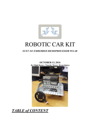
  • 1. ROBOTIC CAR KIT ECET 365 EMBEDDED MICROPROCESSOR W/LAB OCTOBER 13, 2016 By Elijah Barner, Timothy Moore, Bryan Quiroz TABLE of CONTENT
  • 2. Introductions Pg. 3 Block Diagram Pg. 4-5 Components Pg. 6 Getting Started Pg. 7-9 Robot Code Pg. 10-12 Troubleshooting Tips Pg. 13 Caution Pg. 14 Contact Information/Technical Support Pg. 15 References Pg. 16
  • 3. INTRODUCTION Welcome to the ECET Robotic Car Kit. The following kit contain parts for TWR- S12G128 microcontroller tower, SRK + Line kit, and all the associated wires, and connectors to operate the automated robot. This specific model follows a black strip line race track based on the users design. This manual contain information for assembly, troubleshooting tips, schematic diagrams, coding information and software. It also contains contact information for customer service at the end of the manual.
  • 6. Power Supply Subsystems 18650 Lithium Ion Batteries ● Typical Capacity: 3000 mAh ● Min Capacity: 2900 mAh ● Nominal Voltage: 3.7V ● Charging Voltage: 4.35V 12 volt regulator - 7812 ● Max Amperage output:1 amp 5 volt regulator - 7805 ● Max Amperage output:1 amp 5V To 3.3V DC-DC Step-Down Power Supply Buck Module ● Operating Supply Voltage: 4.2 V to 10 V ● Output Current: 800mA ● Output Voltage: 3.3 V Motor Subsystems SN754410NE - H Bridge ● Operating Supply Voltage: 4.5 V to 36 V ● Output Current: 1100 mA Digilent 12v motor ● Max Operating Supply Voltage: 12 V ● Output Current: 240 mA ● Torque: 617 g-cm Sensor Subsystems OPB704 ● Max Collector Current:25 mA ● Vf - Forward Voltage: 1.7 V
  • 7. GETTING STARTED Chassis assembly requires a fillister head screwdriver, needle nose pliers, wire strippers, and the associated mounts with-in the kit.
  • 8. Attach the four sensor with the double sided Velcro strips in the front of the chassis. Attach the microcontroller TWR-12SG128 to the robots chassis via tie-raps or use the extra bracket with screws.
  • 9. Power Supply assembly for +5V (7805CT) voltage regulator. This how the robot will look when it has finally been assembled. Robot Code //sensor 1 pp0 pin A40 black //sensor 2 pp1 pin A39 red //sensor 3 pp2 pin A38 white //sensor 1 pp0 pin A40 black //sensor 2 pp1 pin A39 red //sensor 3 pp2 pin A38 white //sensor 4 pp3 pin A37 yellow //sensor layouton thesensor board1,4,2,3(tied intight notmoving them) #include <hidef.h> /* common defines and macros */ #include "derivative.h" /* derivative-specificdefinitions */ int speed =150; int delayspeed=5; int decrease=25; //function protypes void delay(unsigned int);//delay void test(void); //test void init_PWM01(void); //motor void init_isr(void); //sensor void forward(void); //move forward
  • 10. //void reverse(void); void left(void); void right(void); void stop(void); char sensor; char duty; void main(void) { test(); //initializetest init_PWM01(); //initializemotor init_isr(); //initialize sensors for(;;) { delay(speed); } //end for(;;) } //endmain void test(void) { DDRT=0XFF; DDRP|=0xF0; } void delay(unsigned del) { unsignedinti,j; for (i=0; i<del;i++) { for (j=0; j<2000; j++) { asm("nop")}}; } void init_PWM01(){ PWMCLK &=~0X30; //Chooseclock a for pwm4andpwm5 PWMCLKAB &=~0X30; //Chooseclocka for pwm4 andpwm5 PWMPRCLK =0x04; // clock dividedby 2^4 //PWMSCLA=3; PWMPOL|=0X30; PWMPER4=195; PWMPER5=195; PWME|=0X30; //Enable pwmchannels 4 and 5 onthetower PWMDTY4=0; //Right PWMDTY5=0; //Left } void forward(){ PWMDTY4=speed; PWMDTY5=speed; PTT=0x90; } void stop(){ PWMDTY4=0; PWMDTY5=0; PTT=0x90; } void left(){ PWMDTY4=(speed-decrease); PWMDTY5=(speed/5); //slow down PTT=0x40; } void right(){
  • 11. PWMDTY4=(speed/5); //slow down PWMDTY5=(speed-decrease); PTT=0x80; } void init_isr()//usePP7:PP4 { DDRP &=~0x0F; //use pp0,pp1,pp2,pp3interrupt pins. PPSP &=~0x0F;//choosepulldown PERP |=0x0F;//enablepull PIEP |=0x0F;//enablelocal leveenable asm(cli); // enableglobal levelenable PIFP |=0x0F;// clear allflags on pp0,pp1,pp2,pp3 } //define ISR #pragma CODE_SEG NON_BANKED interrupt((0x10000-0xFF8E)/2-1) void PortP_isr(void) { if ((PIFP&0x02)==0x02) // sensor 2 has gonefrom0 to 1 { left(); delay(delayspeed); PIFP|=0x02; // clearflag } if ((PIFP&0x01)==0x01) // sensor 1 has gonefrom0 to 1 { right(); delay(delayspeed); PIFP|=0x01; // clearflag }// if ((PIFP&0x04)==0x04) // sensor 3 has gonefrom0 to 1 { forward(); //good delay(delayspeed*2); PIFP|=0x04; // clearflag } if ((PIFP&0x08)==0x08) // sensor 4 has gonefrom0 to 1 { forward(); delay(delayspeed*2); PIFP|=0x08; // clearflag } } #pragma CODE_SEG DEFAULT
  • 12. TROUBLESHOOTING TIPS Tip#1: Check to see if both the +5V and 12V regulator output voltages are correct. They supply both voltage to the microcontroller, H-bridge, motors, and sensors. Depending on the model you have some of our robots contain P-mod H-bridge circuits that require an addition two wires. The supply voltages are 5V for the microcontroller and motors. Then 3.3 to 5V for each sensor. Tip#2: Sometimes there will be a message stating that the microcontroller has not been detected by PC. First check to see if you download the latest version of CodeWarrior 5.1 are above with the latest devices driver.
  • 13. Tip#3: The code associate with the robot is preload on the robot. If there is any issues with the code a copy of the program can be found for troubleshooting purpose. It is located at the end of the user manual. (Warning! CodeWarrior IDE interface is case sensitive if any of the code has not been properly type it will result in an error. The code will not compile neither will it upload to the microcontroller.) Tip#4: If and of the hardware is defective please contact us immediately so we can send you any replacement parts. The replacement parts included that are PSU battery compartment, motors, H- bridge, and robot chassis. (If you notice any of the chassis, or electronic hardware missing you should contact us with a brief description of the part and the serial number/ID number located on the part.)
  • 14. Make sure that all of the robot wiring and associated components are properly placed and configure. Because if anything is not properly placed it could lead to possible shortage or possible damage to electronic components. Also check to make sure that the power supply system wiring is placed correctly due to possible fire hazard.
  • 15. CONTACT INFORMATION/TECH SUPPORT If you have any issues regarding the software and hardware please contact us at ebarner777@gmail.com for customer support. If you need to contact our other branches please email us at tim_thegreenbeast@yahoo.comor b_quiroz@live.com.