40+ TOP PIPING_INSTRUMENTATION INTERVIEW QUESTIONS.pdf

qqw

40+ TOP PIPING/INSTRUMENTATION INTERVIEW
QUESTIONS
1.What are instrument categories?
Ans: General, flow, temperature, pressure, level, density.etc.
2.Which instruments are handled by piping department ?
Ans: flame arrestor, breather valve.
3.What are basic functions of instruments?
Ans: To sense, transmit, indicate, read and control.
4.Why block valve is used at the root of an instrument like pressure
indicator?
Ans: They are needed to isolate gauges for maintenance during plant
operation and during hydrostatic testing of piping system. They are
called root valve.
5.Where diaphragm assembly is used ?
Ans: For corrosive, abrasive, viscous fluids. Neutral fluid like glycol
issued on instrument side of diaphragm.
40+ TOP PIPING/INSTRUMENTATION INTERVIEW
QUESTIONS
6.Where and why bleed valve is used in instruments ?
Ans: If the conveyed fluid is hazardous or under high pressure, a branch
fitted with a bleed valve is inserted between the gauge and its isolating
valve, to relieve pressure and /or drain the liquid before servicing the
gauge. It can also be used to sample or for adding a comparison gauge.
7.Why control valves are usually flanged?
Ans: For ease of installation and removal during maintenance.
8.Where ball control valve is used?
Ans: Suitable where nature of fluid is slurry form or handling two phase
flow having particle in suspension, for non-critical and critical fluids
having a fluid temperature to suit the soft seat material and where
relatively low pressure drop is required across control valve. They have
side mounted actuator.
40+ TOP PIPING/INSTRUMENTATION INTERVIEW
QUESTIONS
9.Where butterfly control valve is used ?
Ans: Used for large size piping network handling clean fluid for low
pressure drop across control valve and soft seated control valve. Metal
seated valves used for higher temperatures.
10.How control valve block valves should be located ?
Ans: They should be as close to control valve as possible, considering
drain requirement and hand wheel clearance. At least one of the block
valve should be placed in vertical so that spool can be removed allowing
the control valve to be removed.
11.How TSO valve should be installed ?
Ans: Tight shut off (TSO) valve or reduced port ball control valve should
be installed in vertical for gas service and horizontal ok for liquid service.
12.How bypass valve in control station should be locate
Ans: Near inlet branch point, not above control valve, with 200mm
clearance between actuator and valve.
13.How control station should be supported ?
Ans: It should be supported such that control station piping is self
supporting even if the control valve is removed. Normally, on exit side
elbows of bottom run of control valve.
14.Why and where drain should be located in control valve
assembly ?
Ans: Drain is used to drain the piping between two block valves on two
sides of control valve before removing control valve for maintenance. It
must be located at lowest point of bottom run. One drain is used if
control valve is fails open, and two drain used if control valve fails close,
40+ TOP PIPING/INSTRUMENTATION INTERVIEW
QUESTIONS
as both sides are blocked in this case. For one drain, it should be
upstream side of control valve.
15.Where reducer shall be located in control valve assembly ?
Ans: As close as possible to control valve, preferably directly welded
control valve flanges.
16.How breakup flanges for control valve should be located ?
Ans: One vertical and one horizontal which is achieved by having one
block valve in vertical leg of control valve inlet. Do not place support on
inlet elbow.
17.What are the types of flow measuring devices?
Ans: Orifice plate, Variable area flow meter i.e. rotameter, magnetic flow
meter, turbine flow meter, positive displacement meter.
18.What is piping and instrument scope of supply for orifice meter
?
Ans: Piping provided gaskets and bolts and tapping from orifice plate to
two block valves. Instrument provides orifice plate and flange assembly
and connection down stream of block valves.
19.How orifice flange taps should be oriented ?
Ans: For liquid and steam, it should be horizontal or 45 degree down
from horizontal on both sides. For gas and vapour lines, it should
bevertical or 45 to vertical on both sides. Taps are 0.5 inch.
20.What are straight run requirements of orifice plate ?
Ans: Inlet straight run requirement can be 15D to 20D and outlet straight
run requirement 5D min. It depends on piping configuration and d/D
ration i.e. ration of inside dia of orifice plate and pipe. It is to be
confirmed with instrument engineer in instrument specification of project.
21.What are straight run requirements for vortex meters?
Ans: 5D upstream.
22.Where restriction orifice plates are used ?
40+ TOP PIPING/INSTRUMENTATION INTERVIEW
QUESTIONS
Ans: For effective distribution of fluid in piping network.
23.What are types of level measurement?
Ans: Direct and inferential
24.What are direct methods of level measurement?
Ans: Gauge glasses, reflex or transparent, calibrated tapes or dip sticks
placed in vessel and calibrated directly in level or volume.
25.What are inferential methods of level measurement?
Ans: Hydrostatic head, buoyancy, conductance, radiation, float.
26.What is hydrostatic head type level transmitter?
Ans: Installed directly on nozzle, uses pressure sensing assembly to get
the level. Diaphragm type used for liquids with solids.
27. What are pressure instruments used in chemical industries?
Ans: Manometers, bourden tubes, bellows and diaphragms.
28.What are manometers?
Ans: Single or U type glass tube with mercury or other fluid. Inclined
tube for very low pressure measurement used.
29.What are types of bourdon tubes?
Ans: C, the spiral and helical, most widely used since 100 years.
40+ TOP PIPING/INSTRUMENTATION INTERVIEW
QUESTIONS
30.What are temperature measuring instruments?
Ans: Thermocouples, resistance temperature detectors, filled
system,bimetallic thermometer, thermowells.
31.What thermocouple metals normally used?
Ans: Iron + Constantine, Chromel + Alumel etc.
32.How resistance thermocouples work ?
Ans : Electrical resistance of a conductor changes with temperature.
33.How filled system temperature element work ?
Ans : Bourdon tube, filled with liquid, liquid expands, bourdoun
tubeindicates on scale temperature.
34. How bimetallic thermocouple work ?
Ans: Different expansion of different metals bends the bimetallic strip
toindicate temperature. Invar and Nickel pair used.
35.What is minimum pipe size required for thermowell installation?
Ans: 3”
36.What are design considerations for pipe rack ?
Ans: Rack width, no of levels and elevations, bent spacing,
pipeflexibility, Access and maintenance of each item in pipe rack.
37.What are steps in rack design?
Ans: Generate line routine diagram, Calculate bent spacing, set width of
rack, decide elevations and levels.
38.What is pipe bent?
Ans: Pipe bent consists of a vertical column or columns and a horizontal
structural member or members that carry piping systems, usually above
the headroom.
39.What factors affect pipe span?
Ans: Size, Schedule, liquid or vapor, insulated or bare pipe.
40.What are spandrels?
40+ TOP PIPING/INSTRUMENTATION INTERVIEW
QUESTIONS
Ans: Horizontal structural members located along the
longitudinalcenterline that are used for structural stability, pipe support
orintermediate pipe bents.
41.Which lines placed where in rack ?
Ans: Process lines on lower level, utility lines on top level, instrument
and cable trays on utility level or separate topmost level, Heavy lines
near columns, Flare line outside rack on cantilever beams or inside rack
above top level , steam lines with expansion loops on one side of rack,
line switch orifice runs on one side of rack beside columns for
maintenance using portable ladder.
42.How much extra space required for rack ?
Ans: 20 % extra for future lines.
43.How to route steam lines on rack ?
Ans: Steam headers on top level or rack, determine growth by
multiplying coefficient (From nomograph) of expansion by length of
line.Try anchor in middle, determine growth of each branch and see
weather the have enough flexibility, if not anchor at ¼ th distance on
both sides,determine amount of expansion leg from nomograph, and
decide loopsize. Line that require largest expansion leg should be
located on the outside of the loop.

Recomendados

Piping interview por
Piping interviewPiping interview
Piping interviewAkhilesh Kumar
7.4K vistas5 diapositivas
Instrumentation Interview Questions Download por
Instrumentation Interview Questions DownloadInstrumentation Interview Questions Download
Instrumentation Interview Questions DownloadInstrumentation Tools
662 vistas71 diapositivas
I&C Technical Note por
I&C Technical NoteI&C Technical Note
I&C Technical NoteDenish Vaniyawala
2.1K vistas72 diapositivas
How to Select the Right Valve for your Application por
How to Select the Right Valve for your ApplicationHow to Select the Right Valve for your Application
How to Select the Right Valve for your ApplicationUBMCanon
1.1K vistas24 diapositivas
Hydraulic course manual por
Hydraulic course manualHydraulic course manual
Hydraulic course manualSupreet Kamatagi
5.1K vistas190 diapositivas
flow measurement.ppt por
flow measurement.pptflow measurement.ppt
flow measurement.pptsibtikhokhar
42 vistas85 diapositivas

Más contenido relacionado

Similar a 40+ TOP PIPING_INSTRUMENTATION INTERVIEW QUESTIONS.pdf

Instruments - Part 2 por
Instruments - Part 2Instruments - Part 2
Instruments - Part 2PranavAutomation
271 vistas25 diapositivas
Valves_Control valve_Actuators.ppt por
Valves_Control valve_Actuators.pptValves_Control valve_Actuators.ppt
Valves_Control valve_Actuators.pptKAhmedRehman
13 vistas92 diapositivas
Session 06 - Instruments - Part 2 por
Session 06 - Instruments - Part 2Session 06 - Instruments - Part 2
Session 06 - Instruments - Part 2VidyaIA
209 vistas25 diapositivas
HAZOP.ppt por
HAZOP.pptHAZOP.ppt
HAZOP.pptJayaKarthic1
33 vistas17 diapositivas
Industrial Istrumentation por
Industrial IstrumentationIndustrial Istrumentation
Industrial Istrumentationzmagical
11.3K vistas70 diapositivas
MANUALS FOR FLUID MECHANICS LAB.pdf por
MANUALS FOR FLUID MECHANICS LAB.pdfMANUALS FOR FLUID MECHANICS LAB.pdf
MANUALS FOR FLUID MECHANICS LAB.pdfamgothusandeep
83 vistas119 diapositivas

Similar a 40+ TOP PIPING_INSTRUMENTATION INTERVIEW QUESTIONS.pdf(20)

Valves_Control valve_Actuators.ppt por KAhmedRehman
Valves_Control valve_Actuators.pptValves_Control valve_Actuators.ppt
Valves_Control valve_Actuators.ppt
KAhmedRehman13 vistas
Session 06 - Instruments - Part 2 por VidyaIA
Session 06 - Instruments - Part 2Session 06 - Instruments - Part 2
Session 06 - Instruments - Part 2
VidyaIA209 vistas
Industrial Istrumentation por zmagical
Industrial IstrumentationIndustrial Istrumentation
Industrial Istrumentation
zmagical11.3K vistas
MANUALS FOR FLUID MECHANICS LAB.pdf por amgothusandeep
MANUALS FOR FLUID MECHANICS LAB.pdfMANUALS FOR FLUID MECHANICS LAB.pdf
MANUALS FOR FLUID MECHANICS LAB.pdf
amgothusandeep83 vistas
I am chemical engineer magazine 6 2013 por Hassan Elahi
I am chemical engineer magazine 6 2013I am chemical engineer magazine 6 2013
I am chemical engineer magazine 6 2013
Hassan Elahi4.3K vistas
Anaesthesia machine by Dr. shailendra por Shailendra Satpute
Anaesthesia machine by Dr. shailendra Anaesthesia machine by Dr. shailendra
Anaesthesia machine by Dr. shailendra
Shailendra Satpute3.4K vistas
Piping fundamentals bfl por MN Raghu
Piping fundamentals bflPiping fundamentals bfl
Piping fundamentals bfl
MN Raghu14.1K vistas
Flow through orifice meter por Pulkit Shukla
Flow through orifice meterFlow through orifice meter
Flow through orifice meter
Pulkit Shukla59.8K vistas
application of Direction control valve in automatic transmission por ZIYAD AMBALANGADAN
application of Direction control valve in automatic transmissionapplication of Direction control valve in automatic transmission
application of Direction control valve in automatic transmission
ZIYAD AMBALANGADAN18.2K vistas
Gauge installation and removal procedures por inmer17
Gauge installation and removal proceduresGauge installation and removal procedures
Gauge installation and removal procedures
inmer176.1K vistas
The Humble Check Valve por blenrayaust
The Humble Check ValveThe Humble Check Valve
The Humble Check Valve
blenrayaust1.8K vistas
HYDRAULICS & PNEUMATICS UNIT-4 por Karthik R
HYDRAULICS & PNEUMATICS UNIT-4HYDRAULICS & PNEUMATICS UNIT-4
HYDRAULICS & PNEUMATICS UNIT-4
Karthik R365 vistas

Más de EmmanuelMatutu

1. Usman Ali CV Project Engineer Electrical.pdf por
1. Usman Ali CV Project Engineer Electrical.pdf1. Usman Ali CV Project Engineer Electrical.pdf
1. Usman Ali CV Project Engineer Electrical.pdfEmmanuelMatutu
24 vistas5 diapositivas
A Presentation on Field Instrumentation .pdf por
A Presentation on Field Instrumentation .pdfA Presentation on Field Instrumentation .pdf
A Presentation on Field Instrumentation .pdfEmmanuelMatutu
24 vistas105 diapositivas
API 510 Practice Exam #5 CLOSE BOOK Questions.pdf por
API 510 Practice Exam #5 CLOSE BOOK Questions.pdfAPI 510 Practice Exam #5 CLOSE BOOK Questions.pdf
API 510 Practice Exam #5 CLOSE BOOK Questions.pdfEmmanuelMatutu
315 vistas18 diapositivas
API 653 Exam March 2019-1.pdf por
API 653 Exam March 2019-1.pdfAPI 653 Exam March 2019-1.pdf
API 653 Exam March 2019-1.pdfEmmanuelMatutu
98 vistas18 diapositivas
API-510-OPEN-1.pdf por
API-510-OPEN-1.pdfAPI-510-OPEN-1.pdf
API-510-OPEN-1.pdfEmmanuelMatutu
20 vistas4 diapositivas
API 510 EXAM 2021.pdf por
API 510 EXAM 2021.pdfAPI 510 EXAM 2021.pdf
API 510 EXAM 2021.pdfEmmanuelMatutu
304 vistas14 diapositivas

Más de EmmanuelMatutu(14)

1. Usman Ali CV Project Engineer Electrical.pdf por EmmanuelMatutu
1. Usman Ali CV Project Engineer Electrical.pdf1. Usman Ali CV Project Engineer Electrical.pdf
1. Usman Ali CV Project Engineer Electrical.pdf
EmmanuelMatutu24 vistas
A Presentation on Field Instrumentation .pdf por EmmanuelMatutu
A Presentation on Field Instrumentation .pdfA Presentation on Field Instrumentation .pdf
A Presentation on Field Instrumentation .pdf
EmmanuelMatutu24 vistas
API 510 Practice Exam #5 CLOSE BOOK Questions.pdf por EmmanuelMatutu
API 510 Practice Exam #5 CLOSE BOOK Questions.pdfAPI 510 Practice Exam #5 CLOSE BOOK Questions.pdf
API 510 Practice Exam #5 CLOSE BOOK Questions.pdf
EmmanuelMatutu315 vistas
219816022-Final-Report-on-Electric-Car-Jack-3.pdf por EmmanuelMatutu
219816022-Final-Report-on-Electric-Car-Jack-3.pdf219816022-Final-Report-on-Electric-Car-Jack-3.pdf
219816022-Final-Report-on-Electric-Car-Jack-3.pdf
EmmanuelMatutu26 vistas
27 Common Job Questions and Answer-1.pdf por EmmanuelMatutu
27 Common Job Questions and Answer-1.pdf27 Common Job Questions and Answer-1.pdf
27 Common Job Questions and Answer-1.pdf
EmmanuelMatutu77 vistas

Último

BeatsFest Brand Guidelines Final.pdf por
BeatsFest Brand Guidelines Final.pdfBeatsFest Brand Guidelines Final.pdf
BeatsFest Brand Guidelines Final.pdfEddiePena9
8 vistas12 diapositivas
Sugar Air Kiss Lipstick por
Sugar Air Kiss LipstickSugar Air Kiss Lipstick
Sugar Air Kiss Lipstickaryasheel1
12 vistas5 diapositivas
Final (1).pdf por
Final (1).pdfFinal (1).pdf
Final (1).pdfkarmadjango
10 vistas188 diapositivas
GMP1 powerpoint presentation for maker lab por
GMP1 powerpoint presentation for maker labGMP1 powerpoint presentation for maker lab
GMP1 powerpoint presentation for maker labrpham9987
17 vistas27 diapositivas
Legal PPT Presentation.pptx por
Legal PPT Presentation.pptxLegal PPT Presentation.pptx
Legal PPT Presentation.pptx125071063
5 vistas7 diapositivas
portfolio_20231206_Re.pdf por
portfolio_20231206_Re.pdfportfolio_20231206_Re.pdf
portfolio_20231206_Re.pdfSivaphan Wuttingam
23 vistas65 diapositivas

Último(20)

BeatsFest Brand Guidelines Final.pdf por EddiePena9
BeatsFest Brand Guidelines Final.pdfBeatsFest Brand Guidelines Final.pdf
BeatsFest Brand Guidelines Final.pdf
EddiePena98 vistas
Sugar Air Kiss Lipstick por aryasheel1
Sugar Air Kiss LipstickSugar Air Kiss Lipstick
Sugar Air Kiss Lipstick
aryasheel112 vistas
GMP1 powerpoint presentation for maker lab por rpham9987
GMP1 powerpoint presentation for maker labGMP1 powerpoint presentation for maker lab
GMP1 powerpoint presentation for maker lab
rpham998717 vistas
Legal PPT Presentation.pptx por 125071063
Legal PPT Presentation.pptxLegal PPT Presentation.pptx
Legal PPT Presentation.pptx
1250710635 vistas
GMP2 Powerpoint presentation for maker lab por rpham9987
GMP2 Powerpoint presentation for maker labGMP2 Powerpoint presentation for maker lab
GMP2 Powerpoint presentation for maker lab
rpham998711 vistas
ATPMOUSE_융합2조.pptx por kts120898
ATPMOUSE_융합2조.pptxATPMOUSE_융합2조.pptx
ATPMOUSE_융합2조.pptx
kts12089826 vistas
type book PDF to PPT.pptx por samboggiano
type book PDF to PPT.pptxtype book PDF to PPT.pptx
type book PDF to PPT.pptx
samboggiano7 vistas
DR Portfolio.pptx por robertsd2
DR Portfolio.pptxDR Portfolio.pptx
DR Portfolio.pptx
robertsd226 vistas
Free International civil aviation day template from best presentation design ... por slideceotemplates
Free International civil aviation day template from best presentation design ...Free International civil aviation day template from best presentation design ...
Free International civil aviation day template from best presentation design ...
slideceotemplates15 vistas
Indian wedding dresses design.pdf por Aur Dikhao
Indian wedding dresses design.pdfIndian wedding dresses design.pdf
Indian wedding dresses design.pdf
Aur Dikhao5 vistas
COE catalog-compressed.pdf por daniel103814
COE catalog-compressed.pdfCOE catalog-compressed.pdf
COE catalog-compressed.pdf
daniel10381413 vistas
Dragon Troubles Overview________________ por pulkkinenaliisa
Dragon Troubles Overview________________Dragon Troubles Overview________________
Dragon Troubles Overview________________
pulkkinenaliisa15 vistas

40+ TOP PIPING_INSTRUMENTATION INTERVIEW QUESTIONS.pdf

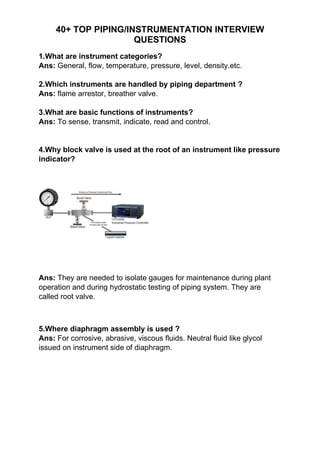
  • 1. 40+ TOP PIPING/INSTRUMENTATION INTERVIEW QUESTIONS 1.What are instrument categories? Ans: General, flow, temperature, pressure, level, density.etc. 2.Which instruments are handled by piping department ? Ans: flame arrestor, breather valve. 3.What are basic functions of instruments? Ans: To sense, transmit, indicate, read and control. 4.Why block valve is used at the root of an instrument like pressure indicator? Ans: They are needed to isolate gauges for maintenance during plant operation and during hydrostatic testing of piping system. They are called root valve. 5.Where diaphragm assembly is used ? Ans: For corrosive, abrasive, viscous fluids. Neutral fluid like glycol issued on instrument side of diaphragm.
  • 2. 40+ TOP PIPING/INSTRUMENTATION INTERVIEW QUESTIONS 6.Where and why bleed valve is used in instruments ? Ans: If the conveyed fluid is hazardous or under high pressure, a branch fitted with a bleed valve is inserted between the gauge and its isolating valve, to relieve pressure and /or drain the liquid before servicing the gauge. It can also be used to sample or for adding a comparison gauge. 7.Why control valves are usually flanged? Ans: For ease of installation and removal during maintenance. 8.Where ball control valve is used? Ans: Suitable where nature of fluid is slurry form or handling two phase flow having particle in suspension, for non-critical and critical fluids having a fluid temperature to suit the soft seat material and where relatively low pressure drop is required across control valve. They have side mounted actuator.
  • 3. 40+ TOP PIPING/INSTRUMENTATION INTERVIEW QUESTIONS 9.Where butterfly control valve is used ? Ans: Used for large size piping network handling clean fluid for low pressure drop across control valve and soft seated control valve. Metal seated valves used for higher temperatures. 10.How control valve block valves should be located ? Ans: They should be as close to control valve as possible, considering drain requirement and hand wheel clearance. At least one of the block valve should be placed in vertical so that spool can be removed allowing the control valve to be removed. 11.How TSO valve should be installed ? Ans: Tight shut off (TSO) valve or reduced port ball control valve should be installed in vertical for gas service and horizontal ok for liquid service. 12.How bypass valve in control station should be locate Ans: Near inlet branch point, not above control valve, with 200mm clearance between actuator and valve. 13.How control station should be supported ? Ans: It should be supported such that control station piping is self supporting even if the control valve is removed. Normally, on exit side elbows of bottom run of control valve. 14.Why and where drain should be located in control valve assembly ? Ans: Drain is used to drain the piping between two block valves on two sides of control valve before removing control valve for maintenance. It must be located at lowest point of bottom run. One drain is used if control valve is fails open, and two drain used if control valve fails close,
  • 4. 40+ TOP PIPING/INSTRUMENTATION INTERVIEW QUESTIONS as both sides are blocked in this case. For one drain, it should be upstream side of control valve. 15.Where reducer shall be located in control valve assembly ? Ans: As close as possible to control valve, preferably directly welded control valve flanges. 16.How breakup flanges for control valve should be located ? Ans: One vertical and one horizontal which is achieved by having one block valve in vertical leg of control valve inlet. Do not place support on inlet elbow. 17.What are the types of flow measuring devices? Ans: Orifice plate, Variable area flow meter i.e. rotameter, magnetic flow meter, turbine flow meter, positive displacement meter. 18.What is piping and instrument scope of supply for orifice meter ? Ans: Piping provided gaskets and bolts and tapping from orifice plate to two block valves. Instrument provides orifice plate and flange assembly and connection down stream of block valves. 19.How orifice flange taps should be oriented ? Ans: For liquid and steam, it should be horizontal or 45 degree down from horizontal on both sides. For gas and vapour lines, it should bevertical or 45 to vertical on both sides. Taps are 0.5 inch. 20.What are straight run requirements of orifice plate ? Ans: Inlet straight run requirement can be 15D to 20D and outlet straight run requirement 5D min. It depends on piping configuration and d/D ration i.e. ration of inside dia of orifice plate and pipe. It is to be confirmed with instrument engineer in instrument specification of project. 21.What are straight run requirements for vortex meters? Ans: 5D upstream. 22.Where restriction orifice plates are used ?
  • 5. 40+ TOP PIPING/INSTRUMENTATION INTERVIEW QUESTIONS Ans: For effective distribution of fluid in piping network. 23.What are types of level measurement? Ans: Direct and inferential 24.What are direct methods of level measurement? Ans: Gauge glasses, reflex or transparent, calibrated tapes or dip sticks placed in vessel and calibrated directly in level or volume. 25.What are inferential methods of level measurement? Ans: Hydrostatic head, buoyancy, conductance, radiation, float. 26.What is hydrostatic head type level transmitter? Ans: Installed directly on nozzle, uses pressure sensing assembly to get the level. Diaphragm type used for liquids with solids. 27. What are pressure instruments used in chemical industries? Ans: Manometers, bourden tubes, bellows and diaphragms. 28.What are manometers? Ans: Single or U type glass tube with mercury or other fluid. Inclined tube for very low pressure measurement used. 29.What are types of bourdon tubes? Ans: C, the spiral and helical, most widely used since 100 years.
  • 6. 40+ TOP PIPING/INSTRUMENTATION INTERVIEW QUESTIONS 30.What are temperature measuring instruments? Ans: Thermocouples, resistance temperature detectors, filled system,bimetallic thermometer, thermowells. 31.What thermocouple metals normally used? Ans: Iron + Constantine, Chromel + Alumel etc. 32.How resistance thermocouples work ? Ans : Electrical resistance of a conductor changes with temperature. 33.How filled system temperature element work ? Ans : Bourdon tube, filled with liquid, liquid expands, bourdoun tubeindicates on scale temperature. 34. How bimetallic thermocouple work ? Ans: Different expansion of different metals bends the bimetallic strip toindicate temperature. Invar and Nickel pair used. 35.What is minimum pipe size required for thermowell installation? Ans: 3” 36.What are design considerations for pipe rack ? Ans: Rack width, no of levels and elevations, bent spacing, pipeflexibility, Access and maintenance of each item in pipe rack. 37.What are steps in rack design? Ans: Generate line routine diagram, Calculate bent spacing, set width of rack, decide elevations and levels. 38.What is pipe bent? Ans: Pipe bent consists of a vertical column or columns and a horizontal structural member or members that carry piping systems, usually above the headroom. 39.What factors affect pipe span? Ans: Size, Schedule, liquid or vapor, insulated or bare pipe. 40.What are spandrels?
  • 7. 40+ TOP PIPING/INSTRUMENTATION INTERVIEW QUESTIONS Ans: Horizontal structural members located along the longitudinalcenterline that are used for structural stability, pipe support orintermediate pipe bents. 41.Which lines placed where in rack ? Ans: Process lines on lower level, utility lines on top level, instrument and cable trays on utility level or separate topmost level, Heavy lines near columns, Flare line outside rack on cantilever beams or inside rack above top level , steam lines with expansion loops on one side of rack, line switch orifice runs on one side of rack beside columns for maintenance using portable ladder. 42.How much extra space required for rack ? Ans: 20 % extra for future lines. 43.How to route steam lines on rack ? Ans: Steam headers on top level or rack, determine growth by multiplying coefficient (From nomograph) of expansion by length of line.Try anchor in middle, determine growth of each branch and see weather the have enough flexibility, if not anchor at ¼ th distance on both sides,determine amount of expansion leg from nomograph, and decide loopsize. Line that require largest expansion leg should be located on the outside of the loop.