2. 21 - 2 AX 15 MANUAL TRANSMISSION ZJ
TRANSMISSION IDENTIFICATION TRANSMISSION SWITCH AND PLUG LOCATIONS
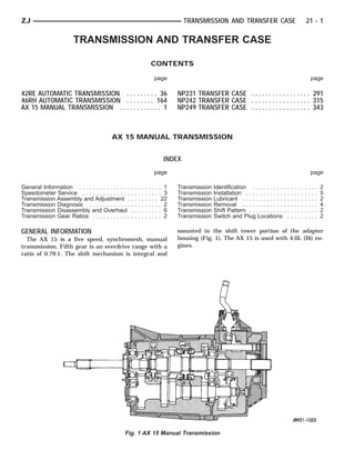
The AX 15 identification code numbers are on the The fill plug is at the driver side of the gear case
bottom surface of the transmission gear case (Fig. 2). (Fig. 4).
The first number represents year of manufacture. The drain plug and backup light switch are on the
For example, 4 would represent 1994. The second passenger side of the gear case (Fig. 5).
and third numbers indicate month of manufacture.
For example, 11 would represent November. The last
series of numbers is the transmission serial number.
TRANSMISSION SHIFT PATTERN
Fig. 4 Fill Plug Location
Fig. 2 Transmission Identification Code Location
The AX 15 shift pattern is shown in Figure 3. First
and second and third and fourth gear ranges are in
an H pattern. Fifth and reverse gear ranges are also
in line at the right of the H pattern (Fig. 3).
Fig. 5 Drain Plug And Backup Light Switch Location
TRANSMISSION GEAR RATIOS
AX 15 transmission gear ratios are:
First gear - 3.83:1
Second gear - 2.33:1
Third gear - 1.44:1
Fourth gear - 1.00:1
Fifth gear - 0.79:1
Fig. 3 AX 15 Shift Pattern Reverse - 4.22:1
TRANSMISSION LUBRICANT
Recommended lubricant for AX 15 transmissions is TRANSMISSION DIAGNOSIS
Mopar SAE 75W-90, API Grade GL-5 gear lubricant.
LOW LUBRICANT LEVEL
Correct lubricant level is from the bottom edge, to
A low transmission lubricant level is generally the
no more than 6 mm (1/4 in.) below the bottom edge of result of a leak, inadequate lubricant fill, or an incor-
the fill plug hole. rect lubricant level check.
Lubricant capacity is approximately 3.10 liters Leaks can occur at the mating surfaces of the gear
(3.27 qts.). case, intermediate plate and adapter housing, or
3. ZJ AX 15 MANUAL TRANSMISSION 21 - 3
from the front/rear seals. A suspected leak could also recommended lubricants is noise, excessive wear,
be the result of an overfill condition. internal bind and hard shifting.
Leaks at the rear of the adapter housing will be Improper clutch release is a frequent cause of hard
from the housing oil seals. Leaks at component mat- shifting. Incorrect adjustment or a worn, damaged
ing surfaces will probably be the result of inadequate pressure plate or disc can cause incorrect release. If
sealer, gaps in the sealer, incorrect bolt tightening, or the clutch problem is advanced, gear clash during
use of a non-recommended sealer. shifts can result.
A leak at the front of the transmission are from the Worn or damaged synchro rings can cause gear clash
front bearing retainer or retainer seal. Lubricant may when shifting into any forward gear. In some new or re-
be seen dripping from the clutch housing after extended built transmissions, new synchro rings may tend to
operation. If the leak is severe, it may also contaminate stick slightly causing hard or noisy shifts. In most
the clutch disc causing slip, grab and chatter. cases, this condition will decline as the rings wear-in.
Transmissions filled from air or electrically powered
lubricant containers can be underfilled. This generally TRANSMISSION NOISE
happens when the container delivery mechanism is im- Most manual transmissions make some noise during
properly calibrated. Always check the lubricant level af- normal operation. Rotating gears can generate a mild
ter filling to avoid an under fill condition. whine that may only be audible at extreme speeds.
A correct lubricant level check can only be made Severe transmission noise is generally the result of
when the vehicle is level; use a drive-on hoist to en- a lubricant problem, or internal component damage.
sure this. Also allow the lubricant to settle for a Insufficient, improper, or contaminated lubricant can
minute or so before checking. These recommenda- promote rapid wear of gears, synchros, shift rails,
tions will ensure an accurate check and avoid an un-
forks and bearings. The overheating caused by a lu-
der-or-overfill condition.
bricant problem, can also lead to gear breakage.
HARD SHIFTING
Hard shifting is usually the result of a low lubri- SPEEDOMETER SERVICE
cant level, improper or contaminated lubricants, com- Rear axle gear ratio and tire size determine speed-
ponent damage, incorrect clutch adjustment, or by a ometer pinion requirements. If the pinion must be re-
damaged clutch pressure plate or disc. placed, refer to the parts catalogue information for
Substantial lubricant leaks can result in gear, shift the correct part.
rail, synchro and bearing damage. If a leak goes un-
detected for an extended period, the first indications SPEEDOMETER ASSEMBLY REMOVAL
of a problem are hard shifting and noise. (1) Raise vehicle.
Incorrect or contaminated lubricants also contrib- (2) Disconnect wires from vehicle speed sensor.
ute to hard shifting. The consequence of using non- (3) Remove adapter clamp and screw (Fig. 6).
Fig. 6 Speedometer Components
4. 21 - 4 AX 15 MANUAL TRANSMISSION ZJ
(4) Remove speed sensor and speedometer adapter
as assembly.
(5) Remove speed sensor retaining screw and re-
move sensor from adapter.
(6) Remove speedometer pinion from adapter.
(7) Inspect sensor and adapter O-rings (Fig. 6). Re-
move and discard O-rings if worn or damaged.
(8) Inspect terminal pins in speed sensor. Clean
pins with Mopar electrical spray cleaner if dirty or
oxidized. Replace sensor if faulty, or pins are loose,
severely corroded, or damaged.
SPEEDOMETER INSTALLATION AND
INDEXING
(1) Thoroughly clean adapter flange and adapter
mounting surface in housing. Surfaces must be clean
for proper adapter alignment and speedometer oper- Fig. 7 Location Of Index Numbers On Speedometer
ation. Adapter
(2) Install new O-rings on speed sensor and speed-
ometer adapter if necessary (Fig. 6).
(3) Lubricate sensor and adapter O-rings with
transmission fluid.
(4) Install vehicle speed sensor in speedometer
adapter. Tighten sensor attaching screw to 2-3 N⅐m
(15-27 in. lbs.) torque.
(5) Install speedometer pinion in adapter.
(6) Count number of teeth on speedometer pinion.
Do this before installing assembly in housing. Then
lubricate pinion teeth with transmission fluid.
(7) Note index numbers on adapter body (Fig. 7).
These numbers will correspond to number of teeth on
pinion.
(8) Install speedometer assembly in housing.
(9) Rotate adapter until required range numbers
are at 6 o-clock position. Be sure range index num- Fig. 8 Marking Propeller Shaft And Axle Yoke
bers correspond to number of teeth on pinion gear. (9) Disconnect wires at transfer case electrical
(10) Install speedometer adapter clamp and retain- switch.
ing screw. Tighten clamp screw to 10-12 N⅐m (90-110 (10) Support transmission with transmission jack.
in. lbs.) torque. Secure transmission on jack with safety chains.
(11) Connect wires to vehicle speed sensor. (11) Support engine with jack positioned under
(12) Lower vehicle and top off transmission fluid clutch housing or oil pan flange.
level if necessary. (12) Remove bolts/nuts attaching rear mount to
crossmember (Fig. 9).
TRANSMISSION REMOVAL (13) Remove rear crossmember.
(1) Shift transmission into Neutral.
(14) Remove transfer case attaching nuts and re-
(2) Raise vehicle on hoist.
move transfer case from transmission.
(3) Remove skid plate.
(15) Lower transmission enough to provide access
(4) Mark front and rear propeller shafts for instal-
to shift lever.
lation alignment (Fig. 8). Then remove shafts.
(5) Disconnect transfer case shift linkage from (16) Reach up and around transmission case and
shift lever, or range lever. unseat shift lever dust boot from transmission shift
(6) Disconnect harness wires at vehicle speed sen- tower (Fig. 10). Move boot upward on shift lever for
sor (Fig. 6). access to lever retainer.
(7) Remove harness wires from clips on transmis- (17) Disengage transmission shift lever as follows:
sion case. (a) Reach up and around transmission case and
(8) Disconnect transmission and transfer case vent press shift lever retainer downward with your fin-
hoses. gers.
5. ZJ AX 15 MANUAL TRANSMISSION 21 - 5
Fig. 9 Transmission Rear Mounting Fig. 10 Shift Lever Attachment
(b) Turn retainer counterclockwise to release it. (6) Reach up and around transmission and insert
(c) Lift lever and retainer out of shift tower (Fig. shift lever in shift tower. Press lever retainer down-
10). It is not necessary to remove shift lever ward and turn it clockwise to lock it in place. Then
from floorpan boot. Simply leave lever in install lever dust boot on shift tower.
place for later installation. (7) Align transfer case and transmission shafts and
(18) Disconnect and remove engine timing sensor. install transfer case. Tighten transfer attaching nuts
Retain sensor attaching screws. to 35 N⅐m (26 ft. lbs.) torque.
(19) Remove clutch slave cylinder from clutch (8) Move adjustable support stand from under en-
housing. Move cylinder aside for working clearance gine and reposition it under transmission. Then re-
and access to other components. move transmission jack.
(20) Remove bolts attaching clutch housing to en- (9) Install rear crossmember. Tighten crossmem-
gine. ber-to-frame bolts to 41 N⅐m (30 ft. lbs.) torque.
(21) Pull transmission rearward until clutch hous- Tighten transmission-to-rear support bolts/nuts to 45
ing is clear of engine. Then remove transmission N⅐m (33 ft. lbs.) torque.
from under vehicle. (10) Install slave cylinder in clutch housing.
Tighten cylinder attaching nuts securely.
TRANSMISSION INSTALLATION (11) Connect or install engine timing sensor, if re-
(1) Mount transmission and clutch housing assem- moved.
bly on transmission jack. Secure assembly with (12) Connect transfer case electrical switch wires.
safety chains. (13) Connect transfer case shift rod to range lever.
(2) Lubricate pilot bearing and transmission input (14) Connect transmission and transfer case vent
shaft splines with Mopar high temperature grease. hoses and indicator switch wires.
(3) Align transmission input shaft and clutch disc (15) Connect backup light switch wires.
splines and seat clutch housing on engine.
(16) Connect vehicle speed sensor wires.
(4) Install and tighten bolts that clutch housing to
(17) Align and install front/rear propeller shafts.
engine. Tighten bolts to 61 N⅐m (45 ft. lbs.) torque.
Tighten shaft U-joint clamp bolts to 19 N⅐m (170 in.
(5) Lower transmission for access to transmission
shift tower. lbs.) torque.
6. 21 - 6 AX 15 MANUAL TRANSMISSION ZJ
(18) Install skid plate if removed. Tighten bolts to (4) Remove gasket from shift tower (Fig. 3).
42 N⅐m (31 ft. lbs.) torque. Tighten stud nuts to 17
N⅐m (150 in. lbs.) torque.
(19) Top off transmission and transfer lubricant
levels.
(20) Lower vehicle.
TRANSMISSION DISASSEMBLY AND OVERHAUL
ADAPTER HOUSING REMOVAL
(1) Remove release bearing, release lever and re-
lease fork from clutch housing. Then remove clutch
housing from transmission.
(2) Remove backup light switch. Then remove
drain plug (Fig. 1) and drain transmission lubricant
into pan.
Fig. 3 Shift Tower Gasket Removal/Installation
(5) Remove shift arm retainer bolt (Fig. 4).
Fig. 1 Drain Plug And Backup Light Switch Location
(3) Remove shift tower bolts and remove tower
from adapter or extension housing (Fig. 2).
Fig. 4 Shift Arm Retainer Bolt Removal/Installation
(6) Loosen and remove restrictor pins (Fig. 5).
Fig. 2 Shift Tower Removal/Installation
Fig. 5 Removing/Installing Restrictor Pins
7. ZJ AX 15 MANUAL TRANSMISSION 21 - 7
(7) Remove shift arm shaft plug (Fig. 6). (10) Remove plug for reverse shift head lock ball.
Plug is at right side of adapter housing near backup
light switch (Fig. 9).
Fig. 6 Removing/Installing Shift Arm Shaft Plug
(4WD) Fig. 9 Removing/Installing Lock Ball Plug
(8) Remove shift arm shaft with large magnet (Fig. (11) Remove lock ball spring with pencil magnet
7). (Fig. 10).
Fig. 10 Removing/Installing Lock Ball Spring
Fig. 7 Removing/Installing Shift Arm Shaft (4WD)
(12) Remove shift head lock ball with pencil mag-
(9) Remove shift arm (Fig. 8).
net (Fig. 11).
Fig. 11 Removing/Installing Shift Head Lock Ball
Fig. 8 Shift Arm Removal/Installation
8. 21 - 8 AX 15 MANUAL TRANSMISSION ZJ
(13) Remove adapter housing bolts (Fig. 12).
(14) Loosen adapter/extension housing with rubber
mallet (Fig. 13).
Fig. 13 Loosening Adapter Housing
(15) Remove housing after loosening it (Fig. 14)
Fig. 14 Adapter Housing Removal
(16) Remove adapter housing oil seal with a pry
tool (Fig. 15).
Fig. 15 Removing Adapter Housing Seal
Fig. 12 Adapter Housing Bolt Locations
9. ZJ AX 15 MANUAL TRANSMISSION 21 - 9
GEAR CASE REMOVAL
(1) Remove bearing retainer bolts and remove re-
tainer (Fig. 16).
Fig. 18 Removing Input Shaft Bearing Snap Ring
Fig. 16 Front Bearing Retainer Removal
(2) Remove retainer oil seal with pry tool (Fig. 17).
Fig. 19 Removing Cluster Gear Front Bearing Snap
Ring
Fig. 17 Front Bearing Retainer Seal Location
(3) Remove input shaft bearing snap ring (Fig. 18).
(4) Remove cluster gear front bearing snap ring
(Fig. 19).
(5) Loosen gear case by tapping it away from inter-
mediate plate with rubber mallet (Fig. 20).
Fig. 20 Loosening Gear Case
10. 21 - 10 AX 15 MANUAL TRANSMISSION ZJ
(6) Remove gear case from geartrain and interme- (2) Remove three lock ball springs and lock balls
diate plate (Fig. 21). from intermediate plate with pencil magnet (Fig. 23).
(7) Remove speedometer gear snap ring and re-
move speedometer gear and spacer from output
shaft.
Fig. 21 Gear Case Removal
FIFTH GEAR AND SYNCHRO ASSEMBLY
REMOVAL
(1) Remove three lock ball plugs from intermediate
plate (Fig. 22).
Fig. 23 Removing/Installing Lock Ball And Spring
Fig. 22 Lock Ball Plug Locations
11. ZJ AX 15 MANUAL TRANSMISSION 21 - 11
Fig. 24 Mounting Intermediate Plate And Geartrain In Vise
(3) Mount intermediate plate and geartrain assem- (5) Remove E-ring that secures reverse shift arm
bly in vise as follows: to fork (Fig. 26).
(a) Insert two spare bolts in one bottom bolt hole
in intermediate plate. Insert bolts from opposite
sides of plates (Fig. 24).
(b) Install enough flat washers under each bolt
head to prevent bolts from touching (Fig. 24).
(c) Tape bolts and washers in place and mount
intermediate plate in vise (Fig. 24).
(d) Clamp vise jaws securely against bolt heads
(Fig. 24). Do not clamp vise jaws on intermedi-
ate plate. Clamp only on bolt heads.
(4) Remove fifth gear snap ring (Fig. 25). Retain
snap ring for assembly reference. It is a select fit
component.
Fig. 26 Reverse Shift Arm E-Ring Removal
Fig. 25 Fifth Gear Snap Ring Removal
12. 21 - 12 AX 15 MANUAL TRANSMISSION ZJ
(6) Remove bolts attaching reverse shift arm
bracket to intermediate plate. Then remove bracket
(Fig. 27).
Fig. 29 Fifth Gear Fork Set Screw Removal
Fig. 27 Reverse Shift Arm Bracket Removal
(7) Remove reverse shift arm and shoe (Fig. 28).
Fig. 30 Fifth Gear Shift Fork Removal
Fig. 28 Reverse Shift Arm And Shoe Removal
(8) Remove fifth gear shift fork set screw (Fig. 29).
(9) Move fifth gear shift rail forward until it clears
shift fork.
(10) Remove fifth gear shift fork from synchro
sleeve (Fig. 30).
(11) Remove reverse shift rail and reverse shift
head as assembly (Fig. 31).
(12) Measure thrust clearance between counter
fifth gear and thrust ring with feeler gauge. Clear-
ance should be 0.10 to 0.40 mm (0.003 to 0.019 in.).
If clearance exceeds limits, gear and/or ring will have
to be replaced. Fig. 31 Reverse Shift Head And Rail Removal
13. ZJ AX 15 MANUAL TRANSMISSION 21 - 13
(13) Loosen fifth spline gear with standard two-jaw
puller (Fig. 32). Position puller jaws behind fifth
counter gear as shown.
Fig. 34 Fifth Gear Synchro Ring Removal
Fig. 32 Loosening Fifth Spline Gear
(14) Remove fifth spline gear (Fig. 33).
Fig. 35 Counter Fifth Gear And Synchro Assembly
Removal
Fig. 33 Fifth Spline Gear Removal
(15) Remove fifth gear synchro ring (Fig. 34).
(16) Remove fifth gear synchro and sleeve assem-
bly (Fig. 35).
(17) Remove counter fifth gear thrust ring (Fig.
36).
Fig. 36 Fifth Gear Thrust Ring Removal
15. ZJ AX 15 MANUAL TRANSMISSION 21 - 15
Fig. 41 Shift Rail Identification
SHIFT RAIL AND FORK REMOVAL
There are a total of five shift rails in the AX 15
transmission. The 1-2, 3-4, fifth gear and front re-
verse shift rails are shown in Figure 41.
Two shift rails are used for reverse gear range. The
front reverse rail is at the forward side of the inter-
mediate plate (Fig. 41). The short rear reverse rail
and reverse shift head are at the rear side of the in-
termediate plate.
It is not necessary to remove the shift rails if
they are in good condition. Only the shift forks
need be removed for access to the shafts and
gears.
(1) Remove fifth gear shift rail (Fig. 41). Catch lock
ball in your hand as rail comes out of intermediate
plate.
(2) Remove 1-2 and 3-4 shift rail C-rings with two
screwdrivers of equal size and length (Fig. 42).
Fig. 42 Shift Rail C-Ring Removal
18. 21 - 18 AX 15 MANUAL TRANSMISSION ZJ
(14) Remove interlock pin from reverse shift rail (3) Tap end of output shaft with mallet to unseat and
(Fig. 53). start rear bearing out of intermediate plate (Fig. 55).
(15) Position shift rails, shift forks, lock balls, in-
terlock plugs and interlock pins on the workbench in
order of removal. This will help in identifying compo-
nents during inspection and assembly.
Fig. 55 Unseating Output Shaft Rear Bearing
(4) Remove output shaft by rocking it lightly until
rear bearing comes out of intermediate plate (Fig. 56).
Fig. 53 Reverse Shift Rail Interlock Pin Removal
OUTPUT SHAFT AND CLUSTER GEAR
REMOVAL
(1) Remove output shaft rear bearing snap ring
(Fig. 54).
(2) Remove cluster gear rear bearing snap ring
(Fig. 54).
Fig. 56 Input And Output Shaft Removal
(5) Remove cluster gear by pulling it straight out
of rear bearing (Fig. 57).
Fig. 57 Cluster Gear Removal
Fig. 54 Removing Bearing Snap Rings
19. ZJ AX 15 MANUAL TRANSMISSION 21 - 19
(6) Remove cluster gear rear bearing from interme- (9) Remove synchro ring from input shaft (Fig. 61).
diate plate (Fig. 58). (10) Remove bearing snap ring and press bearing
off input shaft (Fig. 61).
Fig. 58 Removing Cluster Gear Rear Bearing
Fig. 61 Input Shaft Components
(7) Remove input shaft from output shaft (Fig. 59).
OUTPUT SHAFT DISASSEMBLY
(1) Measure thrust clearance of output shaft first,
second and third gears with feeler gauge (Fig. 62).
• First gear clearance should be 0.10 to 0.40 mm
(0.003 to 0.0197 in).
• Second-third gear clearance should be 0.10 to 0.30
mm (0.003 to 0.0118 in.).
(2) If first gear thrust clearance is incorrect, re-
place gear and thrust washer. If second or third
gear clearance is incorrect, either gear and
bearing, or output shaft flange is worn. Refer to
output shaft inspection in Cleaning and Inspec-
tion section.
Fig. 59 Input Shaft Removal
(8) Remove output shaft pilot bearing from input
shaft (Fig. 60).
Fig. 62 Checking Output Shaft Gear Thrust
Fig. 60 Input Shaft Pilot Bearing Removal Clearance
20. 21 - 20 AX 15 MANUAL TRANSMISSION ZJ
Fig. 63 Output Shaft And Gears
(3) Press fifth gear and rear bearing off rear of Inspect the transmission case. Replace the case if
output shaft. cracked or porous or if any of the bearing and gear
(4) Remove thrust washer, pin, and first gear and bores are damaged.
bearing (Fig. 62).
(5) Remove first/reverse hub snap ring (Fig. 63). Output Shaft Inspection
(6) Remove synchro ring. Measure thickness of the output shaft flange with
(7) Press reverse gear and first/reverse hub off a micrometer (Fig. 64). Minimum allowable flange
shaft as assembly. thickness is 4.70 mm (0.185 in).
(8) Remove remaining synchro ring and second If shaft flange thickness is OK but previously
gear and bearing (Fig. 63). measured second/third gear thrust clearance
(9) Remove snap ring at front of output shaft (Fig. was incorrect (Fig. 62), replace the necessary
63). gear and needle bearing as an assembly.
(10) Press 3-4 hub and sleeve off output shaft as Check diameter of the first, second and third gear
assembly (Fig. 63). bearing surfaces of the output shaft (Fig. 64). Mini-
(11) Remove synchro ring. mum allowable diameters are:
(12) Remove third gear and needle bearing (Fig. • 38.86 mm (1.529 in.) for first gear surface
63). • 46.86 mm (1.844 in.) for second gear surface
• 37.86 mm (1.490 in.) for third gear surface
TRANSMISSION CLEANING AND INSPECTION Check output shaft runout with V-blocks and a dial
Clean the transmission components in solvent. indicator (Fig. 64). Maximum allowable runout is
Then dry the cases, gears, shift mechanism and 0.06 mm (0.0024 in.).
shafts with compressed air. Dry the bearings with Replace the output shaft if any surface measured
clean, dry shop towels only. Never use com- fails to meet stated tolerance.
pressed air on the bearings. This could damage
the bearing rollers. Cluster Gear Inspection
Replace components that are obviously worn, Inspect the cluster gear teeth. Replace the gear if
cracked, chipped or damaged. any teeth are worn or damaged or if the bearing sur-
faces are damaged.
21. ZJ AX 15 MANUAL TRANSMISSION 21 - 21
GEAR AND SYNCHRO INSPECTION
Install the synchro rings on their respective gears.
Rotate each ring on the gear and note synchro action.
Replace any synchro ring that exhibits a lack of
braking action or binds on the gear. Also replace any
ring that is worn or has chipped or broken teeth.
Measure end clearance between the synchro ring
and the gear with a feeler gauge (Fig. 66). Clearance
should be 0.06 mm to 1.6 mm (0.024 to 0.063 in.).
Fig. 66 Checking Synchro Ring End Clearance
Install the needle bearings in the first, second and
third gears. Then install the gears on the output
shaft and check shaft-to-gear clearance with a dial
indicator (Fig. 67).
Fig. 64 Checking Output Shaft Tolerances
Check diameter of the cluster gear journal with a
micrometer (Fig. 65). Minimum allowable diameter is
27.860 mm (1.096 in.).
Fig. 65 Checking Cluster Gear Journal Diameter
Check condition of the cluster gear front bearing.
Replace the bearing if worn, noisy, or damaged.
Fig. 67 Checking Gear-To-Shaft Clearance
22. 21 - 22 AX 15 MANUAL TRANSMISSION ZJ
Maximum allowable clearance is 0.16 mm (0.0063 Inspect the threads in the case, housing and plate.
in.). If any gear exhibits excessive clearance, replace Minor thread damage can be repaired with steel
the gear and needle bearing. thread inserts if necessary. However, do not attempt
Check clearance between the shift forks and syn- to repair if the cracks are evident around any
chro sleeves with a feeler gauge (Fig. 68). Clearance threaded hole.
should not exceed 1.0 mm (0.039 in.). Replace the Inspect the reverse pin in the adapter/extension
synchro sleeve (and matching hub) if clearance ex- housing. Replace the pin if worn or damaged. Refer
ceeds the stated limit. to the replacement procedure in the Transmission As-
sembly section.
TRANSMISSION ASSEMBLY AND ADJUSTMENT
Lubricate the transmission components with gear
lubricant during assembly. Use petroleum jelly to lu-
bricate seal lips and/or hold parts in place during in-
stallation.
FRONT BEARING/BEARING SEAL/REVERSE
SHAFT PIN INSTALLATION
(1) Press front bearing on input shaft. Then secure
bearing with thickest snap ring that will fit in shaft
groove (Fig. 70).
Fig. 68 Checking Shift Fork-To-Sleeve Clearance
Check condition of the reverse idler gear bushing
(Fig. 69). Replace the gear if the bushing is scored or
worn.
Fig. 70 Selecting Input Shaft Front Bearing Snap
Ring
(2) Press front bearing on cluster gear. Then se-
cure bearing with thickest snap ring that will fit in
ring groove on gear (Fig. 71).
(3) Install new oil seals in front bearing retainer
and adapter housing (Fig. 72). Installation depth for
Fig. 69 Reverse Idler Gear Bushing bearing retainer seal is 10.5 to 11.5 mm (0.414 to
Gear Case, Housing And Intermediate Plate 0.453 in.).
(4) Install reverse shaft and shaft retaining pin in
Clean the case, housing and plate with solvent and
adapter housing. Then install access hole plug with
dry with compressed air. Replace any component that
torx bit (Fig. 73).
is cracked, warped or damaged in any way.
23. ZJ AX 15 MANUAL TRANSMISSION 21 - 23
Fig. 71 Selecting Cluster Gear Front Bearing Snap Fig. 73 Installing Reverse Shaft Pin
Ring
OUTPUT SHAFT ASSEMBLY
(1) Lubricate output shaft journals, gears and nee-
dle bearings with recommended gear lubricant.
(2) Install third gear and needle bearing on shaft
(Fig. 63)
(3) Install synchro ring on third gear (Fig. 63).
(4) Assemble 1-2 and 3-4 synchro hubs and sleeves
(Fig.74).
Fig. 74 Synchro Sleeve And Hub Identification
Fig. 72 Oil Seal Installation
(5) Lubricate reverse shaft and gear components
with Mopar 75W-90 gear lubricant.
24. 21 - 24 AX 15 MANUAL TRANSMISSION ZJ
(5) Install inserts and springs in synchro sleeves.
Position open ends of springs 180° apart as shown
(Fig. 75).
Fig. 77 Checking Third Gear Clearance
Fig. 75 Insert Spring Position (12) Assemble first/reverse hub, insert springs, in-
serts, reverse gear and 1-2 sleeve (Fig. 78). Be sure
(6) Install 3-4 synchro hub and sleeve on output
spring ends are 180° apart. Note that splines in
shaft. Press hub onto shaft if necessary.
hub bore are chamfered on one side. Install
(7) Install 3-4 synchro hub snap ring (Fig. 76). Use
hub so chamfered side faces front of output
thickest snap ring that will fit in shaft groove. shaft.
(13) Press assembled hub and sleeve on output
shaft.
(14) Install selective snap ring (Fig. 78). Use thick-
est snap ring that will fit in output shaft groove.
Fig. 76 Installing 3-4 Synchro Hub Snap Ring
(8) Verify third gear thrust clearance with feeler
gauge (Fig. 56). Clearance should be 0.10 to 0.25 mm
(0.004 to 0.010 in.).
(9) Lubricate remaining output shaft gears and Fig. 78 Second Gear And Synchro Assembly
bearings with gear lubricant.
(15) Install synchro ring on first gear (Fig. 79).
(10) Install second gear and needle bearing on (16) Install first gear spacer on shaft and against
shaft (Fig. 78). selective fit snap ring (Fig. 79).
(11) Install synchro ring on second gear (Fig. 78). (17) Install first gear and needle bearing (Fig. 79)
on output shaft.
25. ZJ AX 15 MANUAL TRANSMISSION 21 - 25
(18) Install locating pin and thrust washer on (22) Lubricate input shaft pilot bearing with petro-
shaft (Fig. 79). leum jelly and install bearing in shaft (Fig. 60).
(23) Install input shaft on output shaft (Fig. 59). Be
sure output shaft hub is fully seated in pilot bearing.
OUTPUT SHAFT AND CLUSTER GEAR
INSTALLATION
(1) Mount intermediate plate in vise (Fig. 24).
(2) Lubricate cluster gear journal and rear bearing
with petroleum jelly or gear lubricant.
(3) Install cluster gear rear bearing in intermedi-
ate plate (Fig. 81). Be sure snap ring groove in bear-
ing is rearward as shown.
Fig. 79 First And Fifth Gear Components
(19) Press rear bearing on shaft. Position bearing
snap ring groove so it is closest to end of output shaft.
(20) Check first and second gear thrust clearance
with feeler gauge (Fig. 62).
• First gear clearance should be 0.10 to 0.40 mm
(0.003 to 0.0197 in.)
• Second gear clearance should be 0.10 to 0.30 mm
(0.003 to 0.0118 in.)
(21) Press fifth gear onto output shaft. Then install
select fit snap ring (Fig. 80). Use thickest snap ring
that will fit in shaft groove.
Fig. 81 Installing Cluster Gear Rear Bearing
(4) Start cluster gear into bearing (Fig. 57). Then
hold bearing and push gear into place. Use plastic or
rawhide mallet to seat bearing if necessary.
(5) Start output shaft rear bearing in intermediate
plate. Push shaft rearward and tap intermediate
plate with mallet to seat bearing.
(6) Install snap rings on cluster and output shaft
rear bearings only (Fig. 82). Do not install front
bearing snap rings at this time.
Fig. 80 Selecting Fifth Gear Snap Ring Fig. 82 Installing Rear Bearing Snap Rings
26. 21 - 26 AX 15 MANUAL TRANSMISSION ZJ
Fig. 83 Installing Reverse Idler Gear And Shaft Fig. 84 Installing Rear Bearing Retainer
(7) Install reverse idler gear and shaft (Fig. 83). SHIFT RAIL AND FORK INSTALLATION
(8) Position rear bearing retainer over output shaft The shift rail interlock pins, balls and plugs must
and rear bearing. Be sure bearing retainer tab is be installed in the correct sequence for proper shift-
engaged in reverse idler shaft notch (Fig. 84). ing. Refer to the installation diagram (Fig. 85) during
(9) Install and tighten rear bearing retainer bolts assembly.
to 18 N⅐m (13 ft-lbs). Coat the intermediate plate shift rail bores
and the interlock balls, pins and plugs with a
thick covering of petroleum jelly before assem-
Fig. 85 Shift Rail Ball-Plug-Pin Position
27. ZJ AX 15 MANUAL TRANSMISSION 21 - 27
bly. The jelly will hold the interlock compo-
nents in place making installation easier. Use a
pencil magnet to hold and insert the interlocks.
Then use a small screwdriver to push the inter-
lock components into place.
(1) Coat reverse rail interlock pin with petroleum
jelly and install pin in rail (Fig. 86).
(2) Install reverse shift rail in intermediate plate
(Fig. 87).
(3) Install reverse shift rail C-ring (Fig. 51).
Fig. 86 Installing Reverse Shift Rail Interlock Pin
Fig. 88 Shift Fork Installation
Fig. 87 Installing Reverse Shift Rail And Fork
(4) Position 1-2 and 3-4 shift forks in synchro Fig. 89 Installing Reverse Shift Rail Lock Ball
sleeves (Fig. 88). (9) Coat 3-4 shift rail interlock plug with petro-
(5) Coat reverse rail lock ball with petroleum jelly. leum jelly and install plug in intermediate plate (Fig.
Then tilt reverse shift fork upward and insert ball in 93).
intermediate plate (Fig. 89). (10) Install 3-4 shift rail in intermediate plate and
(6) Coat 1-2 shift rail interlock plug with petro- in both shift forks (Fig. 94).
leum jelly and install it in intermediate plate bore (11) Verify that none of the interlock balls, plugs,
(Fig. 90). or pins were displaced during shift rail installation.
(7) Coat 1-2 shift rail interlock pin with petroleum (12) Install and tighten shift fork setscrews to 20
jelly and insert it in shift rail (Fig. 91). N⅐m (14 ft. lbs.) torque (Fig. 95).
(8) Install 1-2 shift rail in intermediate plate and
1-2 fork (Fig. 92).
29. ZJ AX 15 MANUAL TRANSMISSION 21 - 29
(13) Install 1-2 and 3-4 shift rail C-rings (Fig. 96).
(14) Insert fifth gear shift rail through reverse
shift fork. Then slide rail into intermediate plate
just far enough to secure interlock ball. Do not
fully install shift rail at this time.
Fig. 98 Installing Fifth Gear Thrust Ring
Fig. 96 Installing Shift Rail C-Rings
FIFTH-REVERSE GEAR AND SHIFT
COMPONENT INSTALLATION
(1) Install thrust ring lock ball in cluster gear jour-
nal (Fig. 97). Use petroleum jelly to hold ball in
place.
(2) Install fifth gear thrust ring (Fig. 98). Be sure
thrust ring notch fits over lock ball.
Fig. 99 Assembling Fifth Gear And Synchro
Assembly
Fig. 97 Installing Thrust Ring Lock Ball
(3) Assemble counter fifth gear, synchro sleeve, in-
serts and insert springs (Fig. 99).
(4) Lubricate two-piece bearing with petroleum
jelly and install it in counter fifth gear (Fig. 100).
Fig. 100 Installing Counter Fifth Gear Bearing
30. 21 - 30 AX 15 MANUAL TRANSMISSION ZJ
(5) Install counter fifth gear and synchro assembly (8) Install fifth gear selective snap ring (Fig. 104).
on cluster gear journal (Fig. 101). Use thickest snap ring that will fit in shaft groove.
Fig. 101 Installing Counter Fifth Gear And Sleeve
(6) Install synchro ring in synchro sleeve (Fig. 102).
Fig. 104 Installing Fifth Gear Snap Ring
(9) Install reverse shift head and rail (Fig. 105).
Then install lock ball in shift head.
Fig. 102 Installing Fifth Gear Synchro Ring
(7) Install fifth spline gear on cluster journal (Fig.
103). Tap spline gear into place with plastic mallet if
necessary.
Fig. 105 Installing Reverse Shift Head And Rail
(10) Position fifth gear shift fork in synchro sleeve
(Fig. 106).
(11) Install fifth gear shift rail (Fig. 107). Slide rail
through fork, shift head, intermediate plate and re-
verse shift fork. Be sure interlock ball is not dis-
Fig. 103 Installing Fifth Spline Gear placed during installation.
31. ZJ AX 15 MANUAL TRANSMISSION 21 - 31
Fig. 106 Fifth Gear Shift Fork Installation
Fig. 109 Detent Ball And Spring Installation
(14) Install reverse shift arm bracket (Fig. 110).
Tighten bracket bolts to 18 N⅐m (13 ft. lbs.) torque.
(15) Install reverse shift arm (Fig. 110). Position
Fig. 107 Fifth Gear Shift Rail Installation arm on reverse fork pin and engage it with pin on
shift arm bracket.
(12) Align screw holes in shift fork and rail and in-
(16) Verify that shift arm shoe is engaged in re-
stall set screw (Fig. 108). Tighten screw to 20 N⅐m
verse idler gear. Then secure shift arm to pin on re-
(15 ft. lbs.) torque.
verse fork with new E-clip.
Fig. 108 Shift Fork Set Screw Installation
(13) Install lock balls and springs in intermediate Fig. 110 Reverse Shift Arm And Bracket Installation
plate (Fig. 109). Then install and tighten lock ball GEAR CASE AND ADAPTER INSTALLATION
plugs to 19 N⅐m (14 ft. lbs.) torque. (1) Dismount intermediate plate and gear assem-
blies from vise.
32. 21 - 32 AX 15 MANUAL TRANSMISSION ZJ
(2) Clean mating surfaces of intermediate plate
and transmission gear case with wax and grease re-
mover. Then wipe dry with a clean cloth.
(3) Apply 3 mm (1/8 in.) wide bead of Mopar Gas-
ket Maker, or Loctite 518 to mating surface of gear
case. Keep sealer bead inside bolt holes as shown
(Fig. 111).
Fig. 113 Front Bearing Snap Ring Installation
Fig. 111 Applying Sealer To Gear Case (10) Align and install front bearing retainer (Fig.
(4) Install gear case (Fig. 112). Align shift rails and 114). Be sure retainer is properly seated on case and
bearings in case and tap case into position. bearings.
(5) Verify that gear case is seated on intermediate
plate dowel pins.
Fig. 114 Installing Front Bearing Retainer
(11) Install and tighten front bearing retainer bolts
Fig. 112 Gear Case Installation to 17 N⅐m (12 ft. lbs.) torque.
(6) Install front bearing snap rings (Fig. 113). (12) On models with extension housing, install
(7) Clean gear case and front bearing retainer seal- speedometer gear, lock ball and retaining rings (Fig.
ing surfaces with wax and grease remover. Then 115). Be sure lock ball is engaged in gear.
wipe dry with a clean cloth. (13) Inspect condition of reverse pin in adapter/ex-
(8) Install new seal in front bearing retainer. Then tension housing (Fig. 116). If pin is worn or damaged,
lubricate seal lip with petroleum jelly. Installation replace it as follows:
depth for seal is 10.5 to 11.5 mm (0.413 to 0.453 (a) Remove roll pin access plug (Fig. 117).
in.). (b) Tap roll pin out of housing with pin punch
(9) Apply a 3 mm (1/8 in.) wide bead of Mopar (Fig. 118). Then remove old reverse pin.
Gasket Maker, or Loctite 518 to front bearing re-
tainer sealing surface.
33. ZJ AX 15 MANUAL TRANSMISSION 21 - 33
Fig. 115 Speedometer Gear Installation (2WD Fig. 118 Roll Pin Removal/Installation
Models) (14) Clean sealing surfaces of adapter or extension
housing and intermediate plate with wax and grease
remover. Then wipe dry with a clean cloth.
(15) Apply 3 mm (1/8 in.) wide bead of Mopar Gas-
ket Maker, or Loctite 518 to sealing surface of
adapter or extension housing. Keep sealer bead in-
side bolt holes as shown in Figure 111.
(16) Align and install adapter or extension housing
on intermediate plate (Fig. 119). Be sure housing is
seated on intermediate plate dowel pins.
(17) Coat threads of housing attaching bolts with
Mopar silicone sealer. Then install and tighten bolts
to 37 N⅐m (27 ft. lbs.) torque.
Fig. 116 Reverse Pin Position
Fig. 119 Adapter/Extension Housing Installation
(18) Install detent ball (Fig. 120).
(19) Install detent spring (Fig. 121).
(20) Install detent access plug (Fig. 122). Tighten
plug to 19 N⅐m (14 ft. lbs.) torque.
Fig. 117 Access Plug Removal/Installation (21) Lubricate shift arm shaft and install it in
(c) Install new reverse pin and secure it with roll adapter housing (Fig. 123).
pin. Then install and tighten access plug to 19 N⅐m (22) Position shift arm in adapter housing (Fig.
(14 ft. lbs.) torque. 124). Be sure arm is engaged in shift rails.
(23) Align shift arm with shaft and push shaft into
arm.
34. 21 - 34 AX 15 MANUAL TRANSMISSION ZJ
Fig. 120 Installing Detent Ball Fig. 123 Installing Shift Arm Shaft
Fig. 121 Installing Detent Spring Fig. 124 Shift Arm Installation
(26) Install and tighten restrictor pins to 19 N⅐m
(14 ft. lbs.) torque (Fig. 125).
Fig. 122 Installing Detent Access Plug
(24) Rotate shift arm shaft until set screw holes in
shaft and arm are aligned. Fig. 125 Set Screw And Restrictor Pin Installation
(25) Install and tighten shift arm set screw to 38
N⅐m (28 ft. lbs.) torque (Fig. 125).
35. ZJ AX 15 MANUAL TRANSMISSION 21 - 35
(27) Install and tighten shift arm shaft access plug
to 19 N⅐m (14 ft. lbs.) torque (Fig. 126).
Fig. 127 Shift Tower Gasket Installation
Fig. 126 Access Plug Installation
(28) Position new shift tower gasket on adapter
housing (Fig 127).
(29) Install shift tower (Fig. 128). Tighten tower
attaching bolts to 18 N⅐m (13 ft. lbs.) torque.
(30) Install new gasket on backup light switch and
install switch. Tighten switch to 37 N⅐m (27 ft. lbs.)
torque.
(31) Install new washer on drain plug. Then install
and tighten plug to 37 N⅐m (27 ft. lbs.) torque.
(32) If transmission will be filled with gear lubri-
cant before installation, place transmission in a level
position. Then fill with Mopar 75W-90, grade GL-5
gear lubricant.
Fig. 128 Shift Tower Installation
(33) Install new washer on fill plug. Then install
and tighten plug to 37 N⅐m (27 ft. lbs.) torque.
(34) Install clutch housing and hydraulic concen-
tric bearing.
(35) On models with extension housing, install new
seal in housing with suitable size installer tool (Fig.
129). Lubricate seal lips with petroleum jelly before
installation.
(36) On models with extension housing, install
speedometer driven gear, speedometer adapter and
speed sensor.
Fig. 129 Installing Extension Housing Seal
36. 21 - 36 42RE AUTOMATIC TRANSMISSION ZJ
42RE AUTOMATIC TRANSMISSION
CONTENTS
page page
GENERAL INFORMATION . . . . . . . . . . . . . . . . . 36 42RE TRANSMISSION OVERHAUL . . . . . . . . . . 98
42RE TRANSMISSION DIAGNOSIS . . . . . . . . . . 42 42RE TRANSMISSION/OVERDRIVE
42RE OVERDRIVE UNIT OVERHAUL . . . . . . . . 146 REMOVAL AND INSTALLATION . . . . . . . . . . . 89
42RE IN-VEHICLE SERVICE . . . . . . . . . . . . . . . 77
GENERAL INFORMATION
INDEX
page page
Converter Clutch Engagement . . ... . . . . . . . . . . . 40 Recommended Fluid . . . . . . . . . . . . . . . . . . . . . . . 38
Converter Drainback Valve . . . . ... . . . . . . . . . . . 40 Torque Converter . . . . . . . . . . . . . . . . . . . . . . . . . 38
Electronic Governor Components .. . . . . . . . . . . . 38 Transmission Changes and Parts
Gear Ratios . . . . . . . . . . . . . . . ... . . . . . . . . . . . 38 Interchangeability . . . . . . . . . . . . . . . . . . . . . . . . 41
Governor Pressure Curves . . . . ... . . . . . . . . . . . 40 Transmission Description . . . . . . . . . . . . . . . . . . . . 36
Overdrive Off Switch . . . . . . . . . ... . . . . . . . . . . . 40 Transmission Identification . . . . . . . . . . . . . . . . . . 38
Quick Fill Valve . . . . . . . . . . . . . ... . . . . . . . . . . . 40 Transmission Shifting . . . . . . . . . . . . . . . . . . . . . . 40
TRANSMISSION DESCRIPTION The overdrive clutch is applied in fourth gear only.
The Chrysler 42RE is a 4-speed, fully automatic The direct clutch is applied in all ranges except
transmission with an electronic governor. It is used fourth gear.
with 4.0L engines. The 42RE valve body transfer plate is different. It
Mechanical and hydraulic components in the 42RE is designed to accept a governor body and different
are similar to those in RH series transmissions. The hydraulic circuitry. The governor pressure solenoid
main difference involves the method of producing valve and sensor are mounted in this body. The
governor pressure for shift control. The 42RE uses transfer plate channels line pressure to the solenoid
electronic components to develop governor pressure. valve through the governor body. It also channels
A mechanical governor is used to generate governor governor pressure from the solenoid valve to the gov-
pressure in the RH series. ernor circuit. It is the solenoid valve that develops
First through third gear ranges are provided by the necessary governor pressure.
clutches, bands, overrunning clutch and planetary The 42RE overdrive unit is different from previous
gear sets in the transmission unit. Fourth gear range overdrive units. It is shorter in length as a result of
is provided by the overdrive unit which contains an
eliminating the mechanical governor assembly in-
overdrive clutch, direct clutch, planetary gear set and
cluding the governor tubes and governor support.
overrunning clutch.
38. 21 - 38 42RE AUTOMATIC TRANSMISSION ZJ
TORQUE CONVERTER
A three element torque converter is used for all ap-
plications (Fig. 1). Converter elements consist of the
turbine, stator and impeller. The converter also con-
tains an overrunning clutch and a converter clutch
mechanism.
The converter clutch is an electronically controlled
mechanism. The clutch provides reduced engine
speed and greater fuel economy when engaged.
Clutch engagement also provides reduced transmis-
sion fluid temperatures.
The converter clutch is engaged in fourth gear and
in third gear when the overdrive control switch is in
the OFF position.
An overrunning clutch is mounted in the stator
hub. This one-way clutch prevents the stator from
Fig. 2 Transmission Identification Number And
turning in a direction opposite to engine rotation.
Code Location
This retains the torque multiplication feature of the
converter. • governor pressure sensor
The torque converter is not a serviceable compo- • fluid temperature thermister
nent. It should be replaced as an assembly when di- • transmission speed sensor
agnosis indicates a malfunction has occurred, or • throttle position sensor
when a major malfunction causes debris to enter the • transmission control module (TCM)
converter.
Governor Pressure Solenoid Valve
GEAR RATIOS The solenoid valve generates the governor pressure
Forward Gear ratios for the 42RE transmission needed for upshifts and downshifts. It is an electro-
are: hydraulic device and is located in the governor body
• First gear = 2.74:1 on the valve body transfer plate (Fig. 3).
• Second gear = 1.54:1 The inlet side of the solenoid valve is exposed to
• Third gear = 1.00:1 normal transmission line pressure. The outlet side of
• Fourth gear = 0.69:1. the valve leads to the valve body governor circuit.
The solenoid valve regulates line pressure to pro-
RECOMMENDED FLUID duce governor pressure. The average current sup-
The only fluid recommended for the 42RE trans- plied to the solenoid controls governor pressure. One
mission is Mopar ATF Plus, type 7176. amp current produces zero kPa/psi governor pres-
Dexron II is not really recommended and should
sure. Zero amps sets the maximum governor pres-
only be used when ATF Plus is not available.
sure.
The transmission control module (TCM) supplies
TRANSMISSION IDENTIFICATION
electrical power to the solenoid valve. Operating volt-
The transmission part/identification numbers and
codes are stamped on the left side of the case just age is 12 volts (DC) and is provided through the bat-
above the oil pan gasket surface (Fig. 2). tery terminal on the module.
The first letter/number group is the assembly part The solenoid is polarity sensitive. The TCM ener-
number. The next number group the transmission gizes the solenoid by grounding it through the power
build date. The last number group is the transmis- ground terminal on the transmission control module.
sion serial number. Refer to this information when
ordering replacement parts. Governor Pressure Sensor
The governor pressure sensor measures output
ELECTRONIC GOVERNOR COMPONENTS pressure of the governor pressure solenoid valve (Fig.
Governor pressure is developed and controlled elec- 4).
tronically in the 42RE transmission. Components The sensor output signal provides the necessary
used for development and control of governor pres- feedback to the transmission control module. This
sure include: feedback is needed to adequately control governor
• governor body pressure.
• new design valve body transfer plate
• governor pressure solenoid valve
39. ZJ 42RE AUTOMATIC TRANSMISSION 21 - 39
clutch, when fluid temperature is below approxi-
mately 1°C (30°F).
If fluid temperature exceeds 126°C (260°F), the
transmission control module will cause a 4-3 down-
shift and engage the converter clutch. Engagement is
according to the third gear converter clutch engage-
ment schedule.
The overdrive OFF lamp in the instrument panel,
also illuminates when the shift back to third occurs.
The transmission will not allow fourth gear operation
until fluid temperature decreases to approximately
Fig. 3 Governor Pressure Solenoid Valve 110°C (230°F).
The thermistor is mounted on the solenoid assem-
bly (Fig. 6). It is immersed in transmission fluid at
all times.
Fig. 4 Governor Pressure Sensor
Governor Body And Transfer Plate
A different transfer plate is used with the 42RE
Fig. 6 Thermister Location
valve body. The transfer plate is designed to supply
transmission line pressure to the governor pressure Transmission Speed Sensor
solenoid valve and to return governor pressure. The The speed sensor (Fig. 7), is located in the over-
governor pressure solenoid valve is mounted in the drive gear case. The sensor is positioned over the
governor body. The body is bolted to the lower side of park gear and monitors transmission output shaft ro-
the transfer plate (Fig. 5). tating speed. The sensor used with the 42RE trans-
mission is the same as is used in Chrysler 41TE and
42LE front drive automatic transmissions.
Speed sensor signals are triggered by the park gear
lugs as they rotate past the sensor pickup face. Input
signals from the sensor are sent to the transmission
control module for processing.
The vehicle speed sensor also serves as backup to
the transmission speed sensor. Signals from this sen-
sor are shared with the powertrain control module.
Fig. 5 Governor Body
Transmission Fluid Temperature Thermister
Transmission fluid temperature readings are sup-
plied to the transmission control module by the ther-
mister (Fig. 6). The temperature readings are used to
control engagement of the fourth gear overdrive
clutch, the converter clutch, and governor pressure.
Normal resistance value for the thermister at room
temperature is approximately 1000 ohms.
The transmission control module (TCM) prevents Fig. 7 Transmission Speed Sensor
engagement of the converter clutch and overdrive
40. 21 - 40 42RE AUTOMATIC TRANSMISSION ZJ
Throttle Position Sensor (TPS) CONVERTER CLUTCH ENGAGEMENT
The TPS provides throttle position input signals to The torque converter clutch is engaged by the
both the transmission control module and powertrain clutch solenoid on the valve body. The clutch can be
controller. This input signal is used to determine engaged in third and fourth gear ranges depending
overdrive and converter clutch shift schedule and to on overdrive control switch position.
select the proper governor curve. If the overdrive control switch is in the normal ON
position, the clutch will engage after the shift to
Transmission Control Module (TCM) fourth gear, and above approximately 72 km/h (45
The TCM controls operation of the converter clutch, mph).
overdrive clutch, and governor pressure solenoid. If the control switch is in the OFF position, the
The control module determines transmission shift clutch will engage after the shift to third gear, at ap-
points based on input signals from the transmission proximately 56 km/h (35 mph) at light throttle.
thermistor, transmission output shaft speed sensor,
crankshaft position sensor, vehicle speed sensor and OVERDRIVE OFF SWITCH
throttle position sensor. The overdrive Off switch is located in the instru-
Operating voltage is supplied through the battery ment panel. The switch is a momentary contact de-
terminal on the control module. The ignition voltage vice that signals the TCM to toggle current status of
signal is supplied through a terminal on the ABS the overdrive function. At key-on, overdrive operation
control module. is allowed.
The DRB scan tool can be used to check operation Pressing the switch once causes the overdrive Off
of the control module and transmission electrical mode to be entered and the overdrive Off switch
components. The diagnostic connector (for the scan lamp to be illuminated. Pressing the switch a second
tool) is located under the driver side of the instru- time causes normal overdrive operation to be re-
ment panel. The connector has a 6-way terminal and stored and the overdrive lamp to be turned off.
is blue in color. The normal position for the control switch is the
ON position. The switch must be in this position to
GOVERNOR PRESSURE CURVES energize the solenoid and allow a fourth gear upshift.
There are four governor pressure curves pro- The control switch has an indicator light. The light
grammed into the transmission control module. The
illuminates when the overdrive switch is turned to
different curves allow the control module to adjust
the OFF position, or when illuminated by the trans-
governor pressure for varying conditions.
mission control module.
One curve is used for operation when fluid temper-
The control switch indicator light is also used to
ature is at, or below 10°C (50°F).
A second curve is used when fluid temperature is signal fault flash codes for diagnostic purposes.
at, or above 10°C (50°F) during normal city, or high-
way driving.
QUICK FILL VALVE
A third curve is used during wide open throttle op- The 3-4 quick fill valve provides faster engagement
eration. The fourth curve is used when driving with of the overdrive clutch during 3-4 upshifts. The valve
the transfer case in low range. temporarily bypasses the clutch piston feed orifice at
the start of a 3-4 upshift. This exposes a larger pas-
TRANSMISSION SHIFTING sage into the piston retainer resulting in a much
Shift valve operation with the electronic governor faster clutch fill and apply sequence.
is basically unchanged. The 1-2 and 2-3 upshift se- The quick fill valve does not bypass the regular
quence occurs exactly the same as in non-electronic clutch feed orifice throughout the 3-4 upshift. In-
governor transmissions. stead, once a predetermined pressure develops within
The shift valves are still moved by a combination of the clutch, the valve closes the bypass. Clutch fill is
throttle and governor pressure. The only real differ- then completed through the regular feed orifice.
ence is that governor pressure is generated by elec-
trical components instead of a mechanical valve and CONVERTER DRAINBACK VALVE
weight assembly. The drainback valve is located in the transmission
The conditions under which a shift to fourth will cooler outlet (pressure) line. The valve prevents fluid
not occur, also remain the same. These being: from draining from the converter into the cooler and
• shift to third not yet completed lines when the vehicle is shut down for lengthy peri-
• overdrive switch is in OFF position ods.
• vehicle speed too low for 3-4 shift to occur Production valves have a hose nipple at one end,
• transmission fluid temperature is below 10°C while the opposite end is threaded for a flare fitting.
(50°F) or above 121°C (250°F). Some early valves have hose nipples at both ends. All
41. ZJ 42RE AUTOMATIC TRANSMISSION 21 - 41
valves have an arrow mark (or similar mark) to in- annulus support hub has been remachined to accom-
dicate direction of flow through the valve. modate the new plate tabs.
Plastic check balls are now used in some valve bod-
TRANSMISSION CHANGES AND PARTS ies. The new check balls entered production as a run-
INTERCHANGEABILITY ning change. The plastic and steel check balls are not
1995 transmissions are similar to previous models interchangeable.
but only in appearance. Current transmissions are A converter drainback check valve has been added
dimensionally different and have different hydraulic to the fluid cooler system. The one-way valve is lo-
circuitry. Do not interchange parts. cated in the transmission outlet (pressure) line. The
Transmission changes affect the governor weight valve prevents fluid drainback when the vehicle is
assembly, low-reverse drum, front annulus, boost parked for lengthy periods.
valve tube retainer, fluid cooling system, and valve The boost valve tube retainer has been lengthened
body check balls. and an extra tab added to better secure the tube.
The thrust plate and front annulus have changed.
The thrust plate now has two locating tabs and the
42. 21 - 42 42RE TRANSMISSION DIAGNOSIS ZJ
42RE TRANSMISSION DIAGNOSIS
INDEX
page page
Air Testing Transmission Clutch and Band
Operation . . . . . . . . . . . . . . . . . . . . . . . . . . . . . 48 Effects of Incorrect Fluid Level . . . . . . . . . . . . . . . 43
Analyzing the Road Test . . . . . . . . . . . . . . . . . . . . 44 Fluid Contamination . . . . . . . . . . . . . . . . . . . . . . . 43
Causes of Burned Fluid . . . . . . . . . . . . . . . . . . . . . 43 Hydraulic Pressure Test . . . . . . . . . . . . . . . . . . . . 45
Checking Fluid Level and Condition . . . . . . . . . . . . 42 Overdrive Electrical Controls . . . . . . . . . . . . . . . . . 43
Converter Housing Fluid Leak Diagnosis . . . . . . . . 49 Preliminary Diagnosis . . . . . . . . . . . . . . . . . . . . . . 42
Converter Stall Test . . . . . . . . . . . . . . . . . . . . . . . . 47 Road Testing . . . . . . . . . . . . . . . . . . . . . . . . . . . . 44
Diagnosis and Hydraulic Flow Charts . . . . . . . . . . . 51 Stall Test Analysis . . . . . . . . . . . . . . . . . . . . . . . . . 48
Diagnosis Procedures . . . . . . . . . . . . . . . . . . . . . . 42 Transmission Throttle Valve and Shift Cables . . . . . 44
Diagnostic Trouble Flash Codes . . . . . . . . . . . . . . 44
DIAGNOSIS PROCEDURES (7) Perform air pressure test to check clutch-band
Begin diagnosis by checking the easily accessible operation.
items such as fluid level, fluid condition and throttle
cable/shift linkage adjustments. A road test will de- VEHICLE IS DISABLED
termine if further diagnosis is necessary. (1) Check fluid level and condition.
Procedures outlined in this section should be per- (2) Check for broken, disconnected, binding throt-
formed in the following sequence to realize the most tle valve cable, or lever.
accurate results: (3) Check for cracked, leaking cooler lines, or loose,
(1) Preliminary diagnosis missing pressure port plugs.
(2) Fluid Level and condition (4) Raise vehicle, start engine, shift transmission
(3) Leak tests (if fluid level is low) into gear and note following:
(4) Linkage Adjustment (a) If propeller shafts turn but wheels do not,
(5) Overdrive control switch test problem is with differential or axle shafts.
(6) Road test (b) If propeller shafts do not turn and transmis-
(7) Stall test sion is noisy, stop engine. Remove oil pan, and
(8) Hydraulic pressure test check for debris. If pan is clear, remove transmis-
(9) Air pressure tests sion and check for damaged drive plate, converter,
(10) Analyze test results and consult diagnosis oil pump or input shaft.
charts (c) If propeller shafts do not turn and transmis-
sion is not
PRELIMINARY DIAGNOSIS noisy, perform hydraulic pressure test to deter-
Two basic procedures are required. One procedure mine if problem is a hydraulic or mechanical.
for vehicles that are driveable and an alternate pro-
cedure for disabled vehicles (will not back up or move CHECKING FLUID LEVEL AND CONDITION
forward). (1) Place vehicle on level surface. This is important
for an accurate reading.
VEHICLE IS DRIVEABLE (2) Do not check level until fluid is at normal hot
(1) Check for TCM fault codes with DRB scan tool, operating temperature of approximately 180°F. This
or with fault flash codes at lamp in overdrive Off is necessary to avoid false readings which could pro-
switch. duce under or over fill condition.
(2) Check fluid level and condition. (3) Start and run engine at curb idle speed and ap-
(3) Adjust throttle and gearshift linkage if com- ply parking brakes.
plaint was based on delayed, erratic, or harsh shifts. (4) Shift transmission through all gear ranges and
(4) Road test and note how transmission upshifts, back to Neutral.
downshifts and engages. (5) Clean top of filler tube and dipstick to keep dirt
(5) Perform stall test if complaint is based on slug- out of tube.
gish acceleration. Or, if abnormal throttle opening is (6) Remove dipstick and check fluid level as fol-
needed to maintain normal speeds with a properly lows:
tuned engine. (a) Dipstick has three fluid level indicating
(6) Perform hydraulic pressure test if shift prob- marks which are a MIN dot mark, an OK mark
lems were noted during road test. and a MAX fill arrow mark:
43. ZJ 42RE TRANSMISSION DIAGNOSIS 21 - 43
(b) Correct level is to Full, or MAX arrow mark an auxiliary transmission fluid cooler, a heavy duty
on dipstick. This is correct maximum hot fluid cooling system, and the engine/axle ratio combination
level. Acceptable level is between OK mark and needed to handle heavy loads.
max arrow mark on dipstick.
(c) If level is at, or below MIN/ADD level, add FLUID CONTAMINATION
only enough fluid to restore correct level. Mopar Fluid contamination is generally a result of:
ATF Plus, type 7176 is the required fluid. • adding incorrect fluid
• failure to clean dipstick and fill tube when check-
CAUTION: Do not overfill the transmission. Overfill- ing level
ing may cause leakage out the pump vent which • engine coolant entering fluid
can be mistaken for a pump seal leak. In addition, • internal failure that generates debris
overfilling will also cause fluid aeration and foam- • overheat that generates sludge (fluid breakdown)
ing as the excess fluid is picked up and churned by • failure to reverse flush cooler and lines after re-
the gear train. This will reduce the life of the fluid
pair
significantly.
• failure to replace contaminated converter during
(7) Check fluid condition. Fluid color should range repair
from dark rad to pink and be free of particles and The use of non-recommended fluids can result in
sludge. transmission failure. The usual results are erratic
(a) If fluid is discolored, or smells burned but shifts, slippage, abnormal wear and eventual failure
transmission operation was OK, flush cooler and due to fluid breakdown and sludge formation. Avoid
lines and change fluid and filter. Then road test this condition by using recommended fluids only.
again to confirm proper operation. The dipstick cap and fill tube should be wiped
(b) If fluid is black, dark brown, turned to clean before checking fluid level. Dirt, grease and
sludge, contains extensive amount of metal or fric- other foreign material on the cap and tube could fall
tion material particles, transmission will need over- into the tube if not removed beforehand. Take the
haul (especially if shift problems were evident time to wipe the cap and tube clean before withdraw-
during road test). ing the dipstick.
Engine coolant in the transmission fluid is gener-
EFFECTS OF INCORRECT FLUID LEVEL ally caused by a cooler malfunction. The only remedy
A low fluid level allows the pump to take in air is to replace the radiator as the cooler in the radiator
along with the fluid. Air in the fluid will cause fluid is not a serviceable part. If coolant has circulated
pressures to be low and develop slower than normal. through the transmission for some time, an overhaul
If the transmission is overfilled, the gears churn
may also be necessary; especially if shift problems
the fluid into foam, aerating the fluid and causing
had developed.
the same conditions that occur with a low level. In
The transmission cooler and lines should be reverse
either case, air bubbles cause fluid overheating, oxi-
flushed whenever a malfunction generates sludge
dation and varnish buildup which interferes with
valve, clutch and servo operation. and/or debris. The torque converter should also be re-
Foaming also causes fluid expansion which can re- placed at the same time.
sult in fluid overflow from the transmission vent or Failure to flush the cooler and lines will result in
fill tube. Fluid overflow can easily be mistaken for a re-contamination and a shop comeback. Flushing ap-
leak if inspection is not careful. plies to auxiliary coolers as well. The torque con-
verter and drainback valve should also be replaced
CAUSES OF BURNED FLUID whenever a failure generates sludge and debris. This
Burned, discolored fluid is a result of overheating is necessary because converter flushing procedures
which has two primary causes. will not remove all of the contaminants.
The first cause is a result of restricted fluid flow
through the main and/or auxiliary cooler. This condi- OVERDRIVE ELECTRICAL CONTROLS
tion is usually the result of a faulty or improperly in- The electrical controls governing the shift into
stalled drainback valve, a damaged main cooler, or fourth gear consist of the overdrive off switch in the
severe restrictions in the coolers and lines caused by instrument panel and the overdrive solenoid on the
debris. valve body.
The second primary cause is heavy duty operation The overdrive off switch, valve body solenoid, case
with a vehicle not properly equipped for this type of connectors and related wiring can all be tested with
operation. Trailer towing or similar high load opera- a 12 volt test lamp or a volt/ohmmeter. Check conti-
tion will overheat the transmission fluid if the vehi- nuity of each component when diagnosis indicates
cle is improperly equipped. Such vehicles should have this is necessary.