SlideShare una empresa de Scribd logo
1 de 49
Descargar para leer sin conexión
BUILDING SCIENCEⅡ
BLD61303 PROJECT1
A CASE STUDY ON ACOUSTIC DESIGN
TUTOR: AR.EDWIN CHAN
AKIF ZOLKEPLEE
ANDIKA SETIABUDI
DEENIE H’YATT
ISYRAQ NASIR
JIJI NG
MOHD HAFIZ BIN MASRI ONN
MUHAMMAD AQIL AZLI
NATASYA JASMIN TAMSIR
WATANABE KOHEI
322927
326483
319719
322177
0904Y72861
334944
326479
324222
332172
TABLE OF CONTENTS
1.INTRODUCTION
1.1 AIM & OBJECTIVES
1.2 SITE INFORMATION
1.3 DRAWINGS
2.ACOUSTIC THEORY
2.1 ACOUSTICS IN ARCHITECTURE
2.2 SOUND INTENSITY LEVEL
2.3 REVERBERATION, ATTENUATION, ECHOES
2.4 ACOUSTIC DESIGN FOR AUDITORIUMS
3.METHODOLOGY
3.1 EQUIPMENT
3.2 DATA COLLECTION METHOD
4.ACOUSTIC ANALYSIS
4.1 AUDITORIUM DESIGN
4.2 MATERIALS
4.3 ACOUSTIC TREATMENTS & COMPONENTS
4.4 SOUND & NOISE SOURCES
4.5 SOUND PROPAGATIONS AND RELATED
5.OBSERVATION, DISCUSSION & CONCLUSION
6.REFERENCES
AND SHADOW
PHENOMENA
P2
P3
P10
P13
P23
1
P16
12
1.0 INTRODUCTION
1.1 AIMS & OBJECTIVES
“The aim of this project is expose and introduce students on the actually auditorium
design layout that can influence the effectiveness of the public address(PA) system in
a particular hall.”
ーfrom Module Outline.
The objectives of the report are as follows ;
1. To conduct an in-depth exploration of the auditorium typology based on its
layout, designed with an intention for a specific acoustic performance
according to the needs of its functions.
2. To develop a robust understanding of the physics behind the acoustic quality
of an auditorium.
3. To analyse the relationship between acoustics and the materials, spatial
planning and context of an auditorium.
1.2 SITE INFORMATION
1.2.1 BASIC INFORMATION
Name of Auditorium
Location
Type of Construction
Year of Completion
Total Volume
Total Seat
: Damansara Utama Methodist Church (DUMC)
: Seksyen13, 46200 Petaling Jaya, Selangor, Malaysia
:Multi-purpose auditorium
:2005
:15675m2
:2301 seats
1.2.2 HISTORICAL BACKGROUND
Damansara Utama Methodist church (DUMC) was started in 1980 by a group of 22
professionals and 3 children from SSMS (Sungai Way-Subang Methodist Church). They
started of in a shop lot premise in Damansara Uptown before moving to a factory lot
in Taman Mayang in 1993 to accommodate the fast growing congregation which at
this point had reached 500 people.
The Chinese congregation was started in 1996 as the first vernacular service in DUMC.
At the same time, to accommodate the growing size of the congregation, more
services were held each weekend. By 1998, they were having three celebrations
weekly at this point had reached 500 people.
The numbers continue to grow until 2007 when they moved to the current premise -
Dream Centre. At present time, the congregation stands at 4500 worshippers weekly
across seven different vernacular services.
3
4
1.3 DRAWINGS
GROUND FLOOR PLAN
FIRST FLOOR PLAN
5
2.0 ACOUSTIC THEORY
2.1 ACOUSTICS IN ARCHITECTURE
Architectural acoustics is the science of planning and building a structure to maximise
sound flow and remain effective at extreme capacities. To remain audible comfort in
a building or space, architectural acoustics play a huge role. Certain measure of sound
intensity can be categorized as comfort levels for the users are applied here.
The architectural acoustics are affected by a few factors such as the buildin envelope
design from exterior to interior or vise versa and nature of material used in the
interior design as well as inter-space noise control. Sound source will be identified
before the application of architectural acoustics in a building.
2.2 SOUND INTENSITY LEVEL
Sound intensity is defined as the sound power per unit area (watts/m2
)
2.3 REVERBERATION, ATTENUATION, ECHOES AND SOUND SHADOWS
REVERBERATION ;
In closed interiors of more or less substantial size, the listener does not only hear a
direct sound but a series of its delayed repetitions, that bounce off the confining
surfaces. Because the energy of sound waves is absorbed at every bounce during
their travels, these repetitions become weaker over time. When the source of sound
is turned off, the amount of reflected energy in the room decreases until it is entirely
absorbed. This gradual dying-out of sound is called reverberation.
I(db)=10log10
[I/I0
] Intensity in decibels
RT60=0.161Vm/Sa RT60=Reverb time in seconds
Vm=Volume in cubic meters
Vf
=Volume in cubic feat
Sa
=Total absorption, sabins.
6
ATTENUATION ;
Nature/Energy level of sound as it propagated through mediums of different density
and scatters to the surrounding environment.
ECHOES ;
Sound reflection is as ubiquitous as the cosmic radiation that surroundings us always.
Echoes are defined as sound reflections that is required to the listener with a
perceptible magnitude. Multiple echoes create Reverberations.
SOUND SHADOWS ;
Areas that are shielded from sound waves through mediums that either absorb or
reflect such waves to a considerable degree.
2.4 ACOUSTIC DESIGN FOR AUDITORIUMS
α=Energy Absorbed / Incident Energy
D=VT
Goals ;
1.Preservation of sound intensity (longer the better)
2.Clarity in sound delivery
3.Optimum reverberation time
4.Prevent excessive vibrations
5.Reasonably reduce external noise
7
3.0 METHODOLOGY
3.1 EQUIPMENT LIST
Digital Sound Level Meter Digital Camera
Measuring Tape / Laser Distance Measurer Bluetooth speaker
Tone generator (iPhone app) Human
Specifications of the speaker ;
-Bluetooth transmission distance: 10m
-Bluetooth version: 3.0 ClassⅡ, Support A2DP V1.2, AVRCP V1.4 profiles
-Stage height: 1.4m
Specifications of the tone generator ;
-Frequency range: 0hz-20000hz
-Tested frequency: 125hz, 500hz, 2000hz
8
3.2 DATA COLLECTION METHOD
MEASURING DIMENSIONS
-Accessible areas : Long measuring roll tape (up to 9m)
-Ceiling height : Laser distance measure
0 1 5 10 15 20
MEASURING SOUND INTENSITY LEVEL
1. Set bluetooth speaker at the centre of the stage at 1.6m height from floor.
2. Take a controlled sound level at 1m away from sound source at 125hz, 500hz
and 2000hz.
3. Take a sample at 5m away from sound source at 125hz, 500hz and 2000hz.
4. Repeat sample taking at multiples of 5m.
9
4.0 ACOUSTIC ANALYSIS
4.1 AUDITORIUM DESIGN
4.1.1 SHAPE OF AUDITORIUM
The shape of an auditorium affects the way sound travel from the speaker to the
audience.
The Auditorium is boxed within a structure in a fan shaped arrangement. The
arrangement of the seats in this manner allows the audience to focus at a same point
in the auditorium giving the impact of intimacy not just between the audience and
the stage, but also to each other. Comparing to a horizontal seat distribution, this
arrangement allow audience to face forward without having to shift sideways or turn
their heads to a certain angle to watch the performance.
Other than effective and good seats arrangement, the angle of the auditorium is very
important in delivering the sound from the speaker to the audience. The maximum
angle for optimum listening condition is 140o
for a wide fan arrangement and the
angle of the auditorium is at 150o
which exceeds the limit. Audience situated beyond
the suggested limit are going to experience a poor listening condition. However, the
seats beyond the angle limit is reserved for parents with strollers. By having that,
parents with babies are not going to be affect much by the loud noise coming from
the speaker.
The figure is showing the limit region within 140o
having a good sound quality and the
red region showing seats experiencing low quality of sound.
10
4.1.2 CEILING DESIGN
Auditorium ceiling is different from any other types of room as the ceiling should not
be parallel to the floor. This is to avoid any potential flutter echo that are going to
disrupt the sound quality inside the auditorium. Auditorium ceiling geometry is
designed to direct sound reflection towards the seating area as the volume increased
along the way.
Even though Auditorium ceiling is not like any other room, some design should be
avoided such as domes, cylindrical arches and barreled ceilings due to the creation of
sound foci. As for Damansara Utama Methodist Church, the concave design of the
ceiling panels helps to direct sound collected from the speaker to all the audience.
The ceiling panels function is to distribute sound to the whole auditorium. It helps to
propagate sound even without the help of sound speakers.
Figure above is showing the reflection of sound waves by the ceiling towards the
audience.
11
4.1.3 LEVELING OF SEATS
With the shape of the room and the design of the ceiling, it still does not complete
the commitment on how a good sound quality is going to be produced. The levelling
of seating area in the auditorium is very important as it will affect the sound collect
by the audience based on the place that they are sitting.
There is a total of about 2200 seats in the auditorium arranged in a fan shaped
manner to achieve uniform sound quality. The importance of levelling of the seating
is to ensure all the audience receive almost the same sound quality as the sound
travel to the rear of the room. Despite of having more than 2000 seats, they are
arranged in groups and placed at different 3 different level.
Figure above shows the whole view of the arrangement of seats
12
4.1.4 GROUND FLOOR PIT
At this level, the sound distributed to this seating is not uniform because of the
placement of seats on the same level. The sound intensity decreased as the seat goes
deeper to the far back of the auditorium.
The arrangement of seats at the Ground Floor Pit
4.1.5 GROUND TERRACE
The ground terrace seating level is just behind the ground floor pit. It is elevated from
the ground floor pit but are not evenly place. There are two rows of seat placed on
every steps level as it goes further to the back of the room. This arrangement of seats
will still produce acoustic defects as the sound propagate to the back of the area.
Sound are reflected and diffracted unevenly.
Figure above is showing the seats at terrace elevating from the ground floor
13
4.1.6 FIRST FLOOR TERRACE
This is the best spot in the auditorium for audience to experience a very good sound
quality. The staggered arrangement of seats at this terrace allows the audience to
receive uniform sound distribution which accentuates the music and speech.
4.1.7 SOUND SHADOW AREA
Sound shadow area is a place where sound waves fail to propagate to. Sound shadow
area is also one of the acoustic defects in auditorium. This usually occurs when there
are seats under a big balcony protruding the air-space of the auditorium. This prevent
the sound waves to travel and distribute evenly to the audience at this area.
In the case of this auditorium, the balcony of the upper terrace does not protrude
deeply into the air-space of the auditorium. Thus, it is considered a minor issue
because the sound shadow area is very shallow. The audience seating under the
balcony will still receive the sound waves reflected inside the auditorium.
Figure above is showing the seats arranged in staggered manner
The blue region in the photo above indicates the sound shadow area which is shallow
14
4.2 MATERIALS
4.2.1 MATERIAL TABLE
15
PADDED SEAT : There are two types of padded seat in DUMC altogether, fixed seat
and movable type seat.
CURTAIN : Located at the stage and every entrance/exit door.
16
FLOORING
Carpeted flooring is used most in the auditorium except for the stage area which are
left with timber parquet-ed flooring.
WALLS
The ground level walls is done in half timber panel and half fabric acoustic
foam while the upper two floors are done with acoustic walls finishes and
slanted acoustic wall panels.
ACOUSTIC PANELS
Located at the first floor and attach on plastered brick wall.
17
CEILING : Two types of ceiling can be found in the auditorium which is plastered and gypsum panel
ceiling.
18
4.3 ACOUSTIC TREATMENT & COMPONENTS
4.3.1 WALL PANELS
19
4.3.1.1 ACOUSTIC FOAM PANELS
The first floor of DUMC auditorium wall are lined with acoustic panels of different
sizes and slanted at different angles of 25 and 30 degrees. The design is not only
aesthetically pleasing but the architect also input some design to the panels to
prevent sound of midrange and treble tones from hitting a solid surface and bouncing
back to the stage and create echos, by absorbing the sound energy through the
material.
All the acoustic panels are made up of foam placed on a plywood surface and
wrapped with fabric to allow some space between panels and walls to allow sound to
dissipate and isolate much better.
4.3.1.2 ACOUSTIC TIMBER PANELS
20
Detail section of acoustic timber panel
The gap in between the timber panels allow sound to be absorbed through it on the
face of the panel, which are connected to large cutouts in the back. The timber panel
is also layered with mineral fibre to dampen the sound energy, while the gap
between the wall and the timber panel form resonance due to air vibration thus
creating a Helmholtz absorber.
The design of the timber panels can be altered to give better acoustic performance
by changing the gap between the grooves, the distance between each perforation
pattern and choice of absorbent material. To conclude, smaller gap gives better
acoustic performance.
4.3.1.3 PADDED WALLS
Detail drawing of acoustic foam walls
21
Layers of foam and fabric are used to cover the rear walls of the auditorium
acting as a sound absorbers due to the porosity, this is to stop the reflection of
sound waves back towards the stage.
The padded walls are located on the balcony strip, which is where the air
conditioning diffusers are located. This is to absorb and dampen the sound
caused by the air conditioning diffusers.
4.3.1.4 DRY WALLS
The dry walls located at the side of the stage act as a sound reflector because
of its hard surfaces which have a very low absorption abilities.
Walls that are placed side by side to the dry walls are avoided in the
auditorium to prevent any flutter that could occur during sound reflection.
22
4.3.2 FLOORING
Carpeted Floor
Dream Centre auditorium is mostly covered in layer of carpet except the stage.
The auditorium uses a needle punched carpet, which is created by having
needles punched into a matted layer of fibre, forming a mat of surface fibre.
Needle punched carpet is sound absorbent and can reduce the sound of an
impact as a result of foot traffic. The material is also porous and absorbs
sound energy which reduces echo and reflection.
In between the concrete flooring and the carpet, there is a thin floor
underlayment comprises of a flexible solid mass barrier, a soft foam portion
used to provide further cushioning from footsteps and to fend off the passing of
floor vibrations.
23
4.3.3 CURTAINS
4.3.3.1 VELOUR CURTAINS
The curtains used are heavy sound-absorbing curtains that are located in
strategic locations of the auditorium in order to dampen sound efficiently.
Curtains are located at 2 separate location which are at entry point of
auditorium and at the stage.
Curtains are used and are placed at access points in order to reduce sound
coming from the opening and closing of doors as guest walk in and out of the
auditorium. The curtains are also prevent sound from escaping the space and
leaking into the external area.
The curtains also serve as props purposes, to conceal the back elements of
the stage and as well as reducing the reflection of sound and echoes. The
curtains also prevent the sound leaking from the back end of the stage.
To provide sound more efficiently, the backdrop curtain should be removed and
replaced with a more acoustically reflective material to have the sound
produced bounce of it and reflect it back to the audience.
24
4.3.4 SEATING
PADDED THEATRE SEATING
The auditorium is equipped with two variation of seats which are fixed folding
theatre seating at the back of the auditorium and movable seating at front.
In the auditorium, the seats and audience are one of the components help to
absorb sound. Thus, the placement of the seats have to be correctly planned
to anticipate where the sound is coming from to absorb it to get a good
acoustic of the auditorium.
Both variation of seats are padded and clad in fabric to absorbs sound and
dampen sound energy, which in turn reduces echos.
25
4.3.5 CEILING
PLASTER & GYPSUM BOARD CEILING
The ceiling is primarily plaster-coated and formed of gypsum boards. Plaster
has a hard surface that has poor acoustic absorption qualities and therefore
sound bounces off it and back towards the ground. This ceiling has been
designed in such a way as to properly deflect the sound in the right direction
towards the audience, and avoid surfaces parallel to avoid flutter echoes.
This faux plaster ceiling also act as a hollow section for the ventilation system
and the fly system inside which comprises of lighting rigs.
4.3.6 STAGE
TIMBER PARQUET FLOORING
Wood floors are used for the stage as they are resilient and can overcome foot
traffic better, as well as producing a longer reverberation time due to it being
solid. Reverberation can be the cause of many issues if not appropriately used
in a space, however in this case it is justifiable as it causes sound from the
stage to be more full from every angle of the seating positions.
26
The stage apron located beneath is constructed of a different, but
similar-functioning material, which is a laminated MDF flooring. It has similar
acoustic qualities and are much more affordable compared to solid timber.
27
4.4 SOUND & NOISE SOURCES
In the dictionary sound and noise means vibrations that travel through the air or
another medium and can be heard when they reach a person's or animal's ear. For
this acoustic study we focusing on the positive and negative sounds in an auditorium.
The positive term is “sound” and the negative term is “noise”. All the internal sounds
that the church community want to produce to the audience is considered sound that
is mainly produce by the Audio Visual (A.V) system installed which is mainly
controlled in the control room located in centre of the auditorium in the upper
seating area so that they can optimize the monitorization of the audio and visuals.
Position of the Audio Visual (A.V) system
Noise are unwanted sounds that disturb the users in the auditorium. Noises can be
detected from both external and internal sources from the auditorium where the
noises need to be considered in order to the design noise cancellation and
suppression. Both the sound and noise can be measured in decibel (dB). The main
purpose is to balance and cancel out both sources in order to increase the enjoyment
and comfort of the listeners in the auditorium.
28
4.4.1 SOUND SOURCE
The main source of internal sound comes from the projection of sound that are
amplified by the AV system. The most used are input components that is the audio
hardware that captures and record the sound coming from human voice, instruments
and etc. The components are dynamic microphone, condenser speaker, electric
pickups for guitars, bass and direct input from electrical and musical instruments such
as keyboards. Output components consist of amplifiers, array speakers (ceiling
mounted) and stage monitors.
Types of speaker
As mentioned before the speaker are output components that transfers the sound
and amplifies it. They are 3 main types of speaker that they use inside the
auditorium. Speaker array, subwoofer and monitor.
Speaker Array
There are 3 speaker array suspended in the ceiling with a height of approximately 7
meters of the ground. It is position on the left, right and centre directly in front of the
stage to make sure the this arrangement will produce the best balance of sound
through the auditorium.
Dynamic Microphone Condenser Microphone Electric Guitar Pickup
29
Subwoofers alternate between the 3 speaker array. The purpose of a subwoofer is
mainly to produce lower frequency range , usually at 100 Hz. The total of subwoofers
suspended to the ceiling are 4. The subwoofer is installed in a single unit manner so
that the lower frequencies have slower attenuation and easily reach audiences.
However, the subwoofers are pointed to the concrete wall behind to produce
indirect sound which will be reflected to the audiences via angle ceiling. This method
also aids in reducing the attenuation of lower frequency sounds.
Arrangement of speaker array
The speaker’s arrangement in a 9-8-9 configuration. The speakers are installed in this
order is to avoid from the flat roof which can produce inconsistency in the sound
amplification with in relation with other speakers on ground level.
Subwoofers
30
Monitors
Monitor speakers are intended to give a level recurrence reaction so that the audio
signal is repeated steadfastly, inside the budgetary imperatives of the speaker. The
monitor configuration centre is to avoid boosting bass, treble or different frequencies
trying to make the speaker sound 'great' and to stay away from resonances from the
speaker. The normally reflected sound is deferred and misshaped, which could, for
instance, cause the vocalist to sing out of time with the band.
A different blended tune is frequently steered to the foldback speakers, in light of the
fact that the performers may likewise need to hear a blend without electronic
impacts, for example, reverberation and reverb (this is known as a "dry mix") to
remain in time and tuned in to one another.
In circumstances with poor or missing foldback blends, vocalists may finish up singing
off-tune or out of time with the band.
It is placed on the stage flooring towards the stage facing the performers area to
ensure they will hear their voices properly so that they would not sing out of tune.
This helps for synchronisation between different instruments during the
performance.
Arrangement of Monitor
31
4.4.2 EXTERNAL NOISES
The external noise mainly come from the hallway area surrounding the auditorium
including the entrance foyer and café location outside on the right of the auditorium.
The noise produces by this area approximately 50 dB and 30 dB respectively when the
door of the auditorium is closed.
The doors inside the auditorium focus on soundproofing except for the back door
behind the auditorium which opens directly outside of the DUMC. External noises
such as cars driving by and construction can be hear clearly within this area of the
stage at around 60 dB. The level of noise is also dependant on the event taking place
in the auditorium. During Sunday service for example, when some of the doors left
partially opened and more congregants are around the hallway. There is a significant
increase in external noises being projected to the auditorium compare to the
weekdays.
32
4.4.3 INTERNAL NOISE
Internal noises are mainly produced by the electronical appliances from the AV
system that is located on the stage behind the curtains, server, air conditioning, and
minor static noises from the fluorescent lamps. These noises does not effect when a
event is happening on stage but It can be heard when the hall is silent. Noises is also
created by the materials especially for the wooden flooring located around the
staging area because it is made of timber which produce footsteps noise when people
walk on them as to the carpet that absorbs those noises. Also the opening and closing
of the table from the seats, as well as the opening and closing of the doors.
Air conditioning
The Air-conditioning (AC) system post the most noise during any time of the day as it
is constantly being running and this is because the auditorium requires an AC system
that’s able to regulate the cool temperature inside a hall thus having high amount of
noise when the high velocity blowers supply air into the space that’s located along
the auditorium. This usually coupled with jet diffusers. The uses of this items are
necessary as the diffusers are place around the perimeter of the upper tier due to the
high ceiling. Thus, producing a great stream of cool air to the auditorium.
Different types of diffusers are being use inside the auditorium:
Return
For return/intake air, single deflection return diffusers are used in different sizes
depending on the location. The upper tier has larger air diffusers compares to the
lower tier.
Supply
For supplying air inside the hall, the auditorium uses two types of diffusers that can
be seen in the auditorium namely louver blade diffusers and rounded jet diffusers.
The normal louver blades diffusers are installed where the ceiling is lower such as the
area below the upper tier. The blades deflect in all four directions to spread air
evenly. This diffusers produce noticeable noise but it lower compare to the jet
diffusers. On some area the jet diffusers produce a lot of noise.
33
Jet diffuser are used to supply air to the centre of the auditorium where the
louvered diffusers would be inadequate due to the high ceiling they are placed
at the perimeter of the upper tier pointed towards the centre of the hall. The
noise produce by it is around 55 dB.
Types of lighting fixtures
The lighting fixtures in the auditorium are recessed lighting that use fluorescent
energy saving light bulbs that are embedded in the high ceiling. There are also
strips of fluorescent tubes that place on the ceiling on the upper tier seating.
Louver blade diffuser Jet diffuser
The issue with this fluorescent light is that when it has a large span it requires
a high wattage of electricity thus the static noise comes from the lights is
noticeable which the noises can average at around 35 dB. It usually shadowed
by the noise to the AC system.
34
4.5 SOUND PROPAGATIONS AND RELATED PHENOMENA
4.5.1 SOUND REFLECTION AND ITS ACOUSTIC DEFECTS
The ceiling modified from concave surface – continuously changing profile of short
concave surfaces help to avoid sound concentrations on the sitting area (Figure
4.5.1.1).
Oppositely, the sloping flat ceiling facing frontwards at the end of auditorium is
increasing too much amount of sound to the audiences sitting behind the balcony, by
creating echoes till the last point (Figure 4.5.1.1).
The inward design of the sloping surfaces of flat ceiling in this auditorium does not
produce reflected sound in all points (Figure 4.5.1.2), so the auditorium is not
preferable for speech; as compared to the adaptation of the short and long concave
surfaces (Figure 4.5.1.1), which produce reflection that multiplying the number of
projections till the last point and giving a better envelopment that produce better
quality of music.
Figure 4.5.1.1. The three short concave surfaces of the ceiling produce balanced sound
around the auditorium, yet the sloping flat ceiling surface behind the auditorium
creates echoes.
35
Figure 4.5.1.2. The short sloping surface in the front of auditorium allows sound into
the deep sitting area under balcony.
The short sloping surfaces of the ceiling reduces the amount of sound shadow area,
allowing more amount of sound and almost reaching the last person sitting below the
balcony (Figure 4.5.1.2).
Figure 4.5.1.3. The highlighted side walls produce strong lateral reflections to the
audiences.
The side walls of the auditorium must be reflective because strong lateral reflections
from the both sides can help the audience to feel being enveloped by sound (Figure
4.5.1.3).
36
4.5 SOUND PROPAGATIONS AND RELATED PHENOMENA
4.5.2 ECHOES AND SOUND DELAY
One of the most notable acoustic defects are echoes. Echoes occur when the
audience hears the reflected sound from a source with a notable delay of time after
hearing the direct sound.
R1 = Incident distance
R2 = Reflection distance
D = Direct distance
TD = Delay time
Vs = Speed of sound
Thus, the formula for time delay is [ (TD = R1 + R2 - D) / Vs ] measured in metre
seconds.
Time Delay = R1 + R2 - D
0.34
Figure 4.5.2.1 The representation schematic of time delay
Figure 4.5.2.1 The schematic representation of sound echo occurrence
37
Figure 4.5.2.1 Sound delay analysis in DUMC section drawing; to measure the first
floor sound delay as it defers in distance
Figure 4.5.2.1 Calculations of sound delay for first floor analysis with formula
For speech, the longest acceptable delay time is 40ms (14m); music, the longest
acceptable delay is 100ms (34m). The first floor area of the auditorium is considered
to have acceptable sound delay as from the nearest to the furthest position of seats
for its sound delay falls under 30msec. This states that speech can be legible in the
auditorium.
38
Figure 4.5.2.1 Sound delay analysis in DUMC ground floor drawing; to measure the
ground floor sound delay as to show the reflected sound from the present walls
Figure 4.5.2.1 Calculations of sound delay for first floor analysis with formula
From here we can see that positions of receiver sits near the end of stage is not the
optimum seating area as it have a higher sound delay which affects the speech
legibility. However, overall the auditorium allows for clarity in music as sound delay
value is below 100msec.
39
4.5.3 SOUND DIFFRACTION AND SOUND DIFFUSION
Sound diffracted around the obstacles of the large gaps located at the ceiling surfaces
(Figure 4.5.3).
Diffusion is even scattering of the sound reflections in the space, by mixing with other
propagated sound will resulted in a blending of sound pattern (Figure 4.5.3). The
unevenness of surface is bold in scale (Figure 4.5.3), the dimension across these
individual surface contours are as greater as the length of the waves that they are
intended to diffuse, avoiding the wave reflected as if the surface were flat. This is to
increase the high-frequency reflections both to audiences of exposed sitting area and
stage players because high-frequency sound is less pronounced since close miking is
the recording application. With the sound pressure everywhere the same, the
harassed listener would be theoretically incapable of hearing where the sound had
come from. So, there should always be enough fall-off away from the source for
auditory localisation to the connection with what the listener sees (Figure 4.5.3).
4.5.4 SOUND SHADOW
Figure 4.5.4.1. Sound diffraction around large pillars and corners around ground floor
resulted as sound shadow area.
Sound diffraction occur around large pillars and corners on ground floor of
auditorium (Figure 4.5.4.1), and this result in interference among the diffracted
waves. These create regions of greater and lesser sound intensity (Figure 4.5.4.1),
called sound shadows, after the wave has propagated passed the obstacle.
These shaded spaces around the auditorium fail to propagate sound from the stage
to the audiences far-off beneath the balcony (Figure 4.5.4.1). Moreover, the
extension of the front part of balcony is not risen (Figure 4.5.4.1) so it is not helpful
for gathering acoustical energy and reflecting it to the rear.
40
41
Figure 4.5.4.2. The half-polygonal-ring shape of first floor forms the shaded area
behind the fan shape of ground floor, which has minimal sound shadow.
The arrangement of seats on ground floor is based on the fan shape of ground space,
alongside the balcony above designed accordingly to the half-polygonal-ring shape
(Figure 4.5.4.2). The volume of space below the balcony is gauged to create a minimal
sound shadow effect, by this means to increase that area’s number of far-off
audience that can receive more amount of sound.
42
Figure 4.5.5. The flat surface and opening under the balcony has the depth and height
of D ≤ 2H.
D/H = 5.8 / 3.2 = 1.9 rounded up to 2
The depth of beneath the balcony of this auditorium has been kept equal to twice the
height, D ≤ 2H (Figure 4.5.5). In the case of larger volume with greater depth, speech
serve to be the function of seating area under the balcony because only clear sound
can be reached. Musical instruments generate sounds from 30 Hz to 12,000 Hz which
is much broader than the speech spectrum. In that case, musical sound is not evenly
distributed under the balcony so the audiences received less reverberation sound
during musical performance.
4.5.5 REVERBERATION TIME
43
Approximate reverberation times can be calculated from the Sabine formula:
RT = 0.16
A
RT = Reverberation Time (Sec)
V = Volume of the room (cu.m)
A = Total of Absorption of room surfaces ( sq.m sabins)
X = Absorption of Coefficient of Air
4.5.5.1 VOLUME OF EXPERIMENTAL AUDITORIUM
The reverberant sound in an auditorium dies away with time as the sound is absorbed
within more than one interactions with the surfaces of the room. In a extra reflective
room, it will take longer for the sound to die away and the room is said to be 'live'. In
a very absorbent room, In order to provide a reproducible parameter, a general
reverberation time has been described as the time for the sound to die away to a
degree 60 decibels beneath its original level. The reverberation time can be modeled
to allow an approximate calculation. It is depending on below aspect.
Estimated Floor Area (m2
)
A = 12 x 70 = 840 m2
B = 6.6 x 70 = 462 m2
C = 6.1 x70 = 427 m2
D = 7.1 x 70 = 497 m2
E = 9.7 x 70 = 679 m2
Total Volume of Experimental Auditorium:
57m(W) x 25m(L) x 11m(H) = 15675 m3
44
4.5.5.2 AREA OF FLOOR MATERIALS
4.5.5.3 AREA OF WALL MATERIALS
45
Area of wall materials
Area of Other Materials
46
4.5.5.4 REVERBERATION TIME CALCULATION
RT = 0.16
A
Details:
RT = Reverberation Time (Sec)
V = Volume of the room (cu.m)
A = Total of Abs of room surfaces ( sq.m sabins)
X = Absorption of Coefficient of Air
Total Abs unit = 94.1 + 271 + 1222.2
= 1587.3 m2
sabins
Volume area DUMC : 15675 m3
RT = 0.16 ( 15675) = 1.58 secs
Desirable reverberation times in a given space
147
5.0 OBSERVATION, DISCUSSION & CONCLUSION
5.1 DISCUSSION ON ACOUSTIC DESIGN
There balcony front is made up of flat surfaces that produces long-delay reflections. If
the curved or broken or absorptive-treated surfaces are created on the balcony front,
the time delay sound can be reduced. Beside that, the area under the balcony needs
a larger volume with greater height to increase the reverberation time, with more
reflected sound energy allowed till the end. On the balcony soffit, a convex profile on
sloping surfaces can help the sound to diffuse instead of reflecting them under the
balcony.
5.1 CONCLUSION
After going through recordings, observations, documentations and analysis taken; we
as a team can conclude that DUMC falls under the category of a mixed acoustical use
auditorium in which its acoustical design for speech and performance of music.
Despite being a mixed used auditorium, it does not cater well for talks or speeches
throughout the whole auditorium without the aid of speakers. Having a speaker for
the use of an acoustical design is a statement which can be classified as not a great
acoustical response for the auditorium. However, the auditorium do cater for musical
performance more than a speech due to the optimal sound echo and reverberation
time given for music to perform better even without the aid of speakers.
This project enables us to understood the importance of architectural acoustic design
and response based on the typology, shape and function of the auditorium. We too
had understood how specific adjustments of acoustics are needed to cater of the
programmatic demands of an auditorium in general. The analysis made clear the
relationship between the acoustic and materials, spatial planning with its surrounding
context and certain design principles for what great auditorium has to concern. The
understanding at these relationships would greatly benefit us in future design
projects as acoustical design response is actually a necessity in our life.
148
6.0 REFERENCES
-Reid, E. (n.d.). Understanding buildings a multidisciplinary approach.
-Cavanaugh, W., Tocci, G. and Wilkes, J. (2010). Architectural acoustics. Hoboken, N.J.:
John Wiley & Sons.
-Long, M. (2014). Architectural acoustics. Amsterdam [etc.]: Elsevier Academic Press.
-Gupta, S. (n.d.). Introduction to Auditorium Design: Balcony and Ceiling Design.
-R. B. Newman, “Acoustics” in J. H. Callender (ed.), Time-Saver Standards for
Architectural Design Data, McGraw-Hill, New York, 1974, p. 696.
-(2006, May). Retrieved from
http://www.industrial-electronics.com/measurement-testing-com/architectual-acous
tics-2-SOUND-ABSORPTION-2.html
-Groove. (2011, January). Retrieved from
http://www.stil-acoustics.co.uk/Timber-Acoustic/Linear.html?COLLCC=2138749363&
-Soundsorb « Malaysia Acoustic Ceiling And Wall Panel – E-acoustic Sdn. Bhd. (n.d.).
Retrieved from http://www.eacoustic.com.my/our-products/soundsorb/

Más contenido relacionado

La actualidad más candente

Cempaka sari auditorium
Cempaka sari auditoriumCempaka sari auditorium
Cempaka sari auditoriumCarlson Ko
 
PJCC AUDITORIUM COM.pptx
PJCC AUDITORIUM COM.pptxPJCC AUDITORIUM COM.pptx
PJCC AUDITORIUM COM.pptxSNEHALGUPTA13
 
Building science 2 report "Case study" on Acoustic Design.
Building science 2 report "Case study" on Acoustic Design.Building science 2 report "Case study" on Acoustic Design.
Building science 2 report "Case study" on Acoustic Design.Digital Space Consultancy Ltd
 
Shanmukhananda hall, sion - ACOUSTICS - AUDITORIUM - MUMBAI
Shanmukhananda hall, sion - ACOUSTICS - AUDITORIUM - MUMBAIShanmukhananda hall, sion - ACOUSTICS - AUDITORIUM - MUMBAI
Shanmukhananda hall, sion - ACOUSTICS - AUDITORIUM - MUMBAIDijo Mathews
 
Auditorium : SHANTANAND Temple of Fine Art Case Study Presentation
Auditorium : SHANTANAND Temple of Fine Art Case Study PresentationAuditorium : SHANTANAND Temple of Fine Art Case Study Presentation
Auditorium : SHANTANAND Temple of Fine Art Case Study PresentationQuinn Liew
 
THE ACOUSTIC DESIGN OF CONNEXION@NEXUS
THE ACOUSTIC DESIGN OF CONNEXION@NEXUSTHE ACOUSTIC DESIGN OF CONNEXION@NEXUS
THE ACOUSTIC DESIGN OF CONNEXION@NEXUSYen Min Khor
 
a case study of acoustic design presentation
a case study of acoustic design presentationa case study of acoustic design presentation
a case study of acoustic design presentationYen Min Khor
 
Architectural acoustics
Architectural acoustics Architectural acoustics
Architectural acoustics Geeva Chandana
 
Auditorium Architecture planning
Auditorium Architecture planningAuditorium Architecture planning
Auditorium Architecture planningDanishPathan7
 
An Acoustic Case Study on Calvary Convention Centre Report
An Acoustic Case Study on Calvary Convention Centre ReportAn Acoustic Case Study on Calvary Convention Centre Report
An Acoustic Case Study on Calvary Convention Centre Reportdouglasloon
 
Building Science 2 - Auditorium : A Case Study on Acoustic Design - Report ft...
Building Science 2 - Auditorium : A Case Study on Acoustic Design - Report ft...Building Science 2 - Auditorium : A Case Study on Acoustic Design - Report ft...
Building Science 2 - Auditorium : A Case Study on Acoustic Design - Report ft...Nekumi Kida
 
shah auditorium Case study
shah auditorium Case study  shah auditorium Case study
shah auditorium Case study sonali parashar
 
A Case Study On Room Acoustic
A Case Study On Room AcousticA Case Study On Room Acoustic
A Case Study On Room AcousticKalvin Bong
 
Bsc acoustic
Bsc acoustic Bsc acoustic
Bsc acoustic WC Yan
 
Acoustic case study
Acoustic case studyAcoustic case study
Acoustic case studyEsa Shaikh
 
Acousticsandsoundinsulationsby K R Thanki
Acousticsandsoundinsulationsby K R ThankiAcousticsandsoundinsulationsby K R Thanki
Acousticsandsoundinsulationsby K R ThankiKrunal Thanki
 

La actualidad más candente (20)

Cempaka sari auditorium
Cempaka sari auditoriumCempaka sari auditorium
Cempaka sari auditorium
 
PJCC AUDITORIUM COM.pptx
PJCC AUDITORIUM COM.pptxPJCC AUDITORIUM COM.pptx
PJCC AUDITORIUM COM.pptx
 
Building science 2 report "Case study" on Acoustic Design.
Building science 2 report "Case study" on Acoustic Design.Building science 2 report "Case study" on Acoustic Design.
Building science 2 report "Case study" on Acoustic Design.
 
Shanmukhananda hall, sion - ACOUSTICS - AUDITORIUM - MUMBAI
Shanmukhananda hall, sion - ACOUSTICS - AUDITORIUM - MUMBAIShanmukhananda hall, sion - ACOUSTICS - AUDITORIUM - MUMBAI
Shanmukhananda hall, sion - ACOUSTICS - AUDITORIUM - MUMBAI
 
Auditorium acoustics
Auditorium acousticsAuditorium acoustics
Auditorium acoustics
 
Auditorium : SHANTANAND Temple of Fine Art Case Study Presentation
Auditorium : SHANTANAND Temple of Fine Art Case Study PresentationAuditorium : SHANTANAND Temple of Fine Art Case Study Presentation
Auditorium : SHANTANAND Temple of Fine Art Case Study Presentation
 
THE ACOUSTIC DESIGN OF CONNEXION@NEXUS
THE ACOUSTIC DESIGN OF CONNEXION@NEXUSTHE ACOUSTIC DESIGN OF CONNEXION@NEXUS
THE ACOUSTIC DESIGN OF CONNEXION@NEXUS
 
a case study of acoustic design presentation
a case study of acoustic design presentationa case study of acoustic design presentation
a case study of acoustic design presentation
 
Architectural acoustics
Architectural acoustics Architectural acoustics
Architectural acoustics
 
Auditorium Architecture planning
Auditorium Architecture planningAuditorium Architecture planning
Auditorium Architecture planning
 
An Acoustic Case Study on Calvary Convention Centre Report
An Acoustic Case Study on Calvary Convention Centre ReportAn Acoustic Case Study on Calvary Convention Centre Report
An Acoustic Case Study on Calvary Convention Centre Report
 
Building Science 2 - Auditorium : A Case Study on Acoustic Design - Report ft...
Building Science 2 - Auditorium : A Case Study on Acoustic Design - Report ft...Building Science 2 - Auditorium : A Case Study on Acoustic Design - Report ft...
Building Science 2 - Auditorium : A Case Study on Acoustic Design - Report ft...
 
shah auditorium Case study
shah auditorium Case study  shah auditorium Case study
shah auditorium Case study
 
Auditorium ACOUSTICS
Auditorium ACOUSTICSAuditorium ACOUSTICS
Auditorium ACOUSTICS
 
A Case Study On Room Acoustic
A Case Study On Room AcousticA Case Study On Room Acoustic
A Case Study On Room Acoustic
 
Auditorium case study 1
Auditorium case study 1Auditorium case study 1
Auditorium case study 1
 
auditorium
auditoriumauditorium
auditorium
 
Bsc acoustic
Bsc acoustic Bsc acoustic
Bsc acoustic
 
Acoustic case study
Acoustic case studyAcoustic case study
Acoustic case study
 
Acousticsandsoundinsulationsby K R Thanki
Acousticsandsoundinsulationsby K R ThankiAcousticsandsoundinsulationsby K R Thanki
Acousticsandsoundinsulationsby K R Thanki
 

Similar a ACOUSTIC DESIGN FOR DREAM CENTRE HALL

BSCIENCE ACOUSTIC
BSCIENCE ACOUSTIC BSCIENCE ACOUSTIC
BSCIENCE ACOUSTIC Pei Di
 
Building Science P01
Building Science P01Building Science P01
Building Science P01yincytwincy
 
Building Science II Project 1 - Acoustic Design
Building Science II Project 1 - Acoustic DesignBuilding Science II Project 1 - Acoustic Design
Building Science II Project 1 - Acoustic DesignNik Ahmad Munawwar Nik Din
 
CCEC Acoustic Design Analysis
CCEC Acoustic Design AnalysisCCEC Acoustic Design Analysis
CCEC Acoustic Design AnalysisLee Wan Xuan
 
Building Science 2 Project 1 report - ASWARA
Building Science 2 Project 1 report - ASWARABuilding Science 2 Project 1 report - ASWARA
Building Science 2 Project 1 report - ASWARATan Jaden
 
Acoustical analysis of DPAC
Acoustical analysis of DPACAcoustical analysis of DPAC
Acoustical analysis of DPACJy Chong
 
Building Science Report Project 1
Building Science Report Project 1Building Science Report Project 1
Building Science Report Project 1Ong Shi Hui
 
DUMC BSCIENCE slides
DUMC BSCIENCE slidesDUMC BSCIENCE slides
DUMC BSCIENCE slidesJia Jun Chok
 
B science 2 PROJECT 1 shantanand auditorium(1)
B science 2 PROJECT 1   shantanand auditorium(1)B science 2 PROJECT 1   shantanand auditorium(1)
B science 2 PROJECT 1 shantanand auditorium(1)ShiLikHong
 
P1 building science 2
P1 building science 2 P1 building science 2
P1 building science 2 Canisius Bong
 
MODULE-VI BUILDING PLANNING AND DESIGN BTCVC606
MODULE-VI BUILDING PLANNING AND DESIGN BTCVC606MODULE-VI BUILDING PLANNING AND DESIGN BTCVC606
MODULE-VI BUILDING PLANNING AND DESIGN BTCVC606Dr. BASWESHWAR JIRWANKAR
 
Building Science II Project 1 Report
Building Science II Project 1 ReportBuilding Science II Project 1 Report
Building Science II Project 1 ReportBolin Loong
 
Building Science Auditorium Report
Building Science Auditorium ReportBuilding Science Auditorium Report
Building Science Auditorium ReportChong Chin Pin
 
Auditorium : SHANTANAND Temple of Fine Art Case Study
Auditorium : SHANTANAND Temple of Fine Art Case StudyAuditorium : SHANTANAND Temple of Fine Art Case Study
Auditorium : SHANTANAND Temple of Fine Art Case StudyQuinn Liew
 
b science acoustic
 b science acoustic b science acoustic
b science acousticPei Di
 

Similar a ACOUSTIC DESIGN FOR DREAM CENTRE HALL (20)

BSCIENCE ACOUSTIC
BSCIENCE ACOUSTIC BSCIENCE ACOUSTIC
BSCIENCE ACOUSTIC
 
Bsci ii (1)
Bsci ii (1)Bsci ii (1)
Bsci ii (1)
 
Building Science P01
Building Science P01Building Science P01
Building Science P01
 
Compilationd
CompilationdCompilationd
Compilationd
 
Compilation
CompilationCompilation
Compilation
 
Building Science II Project 1 - Acoustic Design
Building Science II Project 1 - Acoustic DesignBuilding Science II Project 1 - Acoustic Design
Building Science II Project 1 - Acoustic Design
 
CCEC Acoustic Design Analysis
CCEC Acoustic Design AnalysisCCEC Acoustic Design Analysis
CCEC Acoustic Design Analysis
 
_CONCERT HALL ACOUSTICS.pdf
_CONCERT HALL ACOUSTICS.pdf_CONCERT HALL ACOUSTICS.pdf
_CONCERT HALL ACOUSTICS.pdf
 
Building Science 2 Project 1 report - ASWARA
Building Science 2 Project 1 report - ASWARABuilding Science 2 Project 1 report - ASWARA
Building Science 2 Project 1 report - ASWARA
 
Acoustical analysis of DPAC
Acoustical analysis of DPACAcoustical analysis of DPAC
Acoustical analysis of DPAC
 
Building Science Report Project 1
Building Science Report Project 1Building Science Report Project 1
Building Science Report Project 1
 
DUMC BSCIENCE slides
DUMC BSCIENCE slidesDUMC BSCIENCE slides
DUMC BSCIENCE slides
 
B science 2 PROJECT 1 shantanand auditorium(1)
B science 2 PROJECT 1   shantanand auditorium(1)B science 2 PROJECT 1   shantanand auditorium(1)
B science 2 PROJECT 1 shantanand auditorium(1)
 
P1 building science 2
P1 building science 2 P1 building science 2
P1 building science 2
 
MODULE-VI BUILDING PLANNING AND DESIGN BTCVC606
MODULE-VI BUILDING PLANNING AND DESIGN BTCVC606MODULE-VI BUILDING PLANNING AND DESIGN BTCVC606
MODULE-VI BUILDING PLANNING AND DESIGN BTCVC606
 
Building Science II Project 1 Report
Building Science II Project 1 ReportBuilding Science II Project 1 Report
Building Science II Project 1 Report
 
Building Science Auditorium Report
Building Science Auditorium ReportBuilding Science Auditorium Report
Building Science Auditorium Report
 
B science report
B science reportB science report
B science report
 
Auditorium : SHANTANAND Temple of Fine Art Case Study
Auditorium : SHANTANAND Temple of Fine Art Case StudyAuditorium : SHANTANAND Temple of Fine Art Case Study
Auditorium : SHANTANAND Temple of Fine Art Case Study
 
b science acoustic
 b science acoustic b science acoustic
b science acoustic
 

Último

9548086042 for call girls in Indira Nagar with room service
9548086042  for call girls in Indira Nagar  with room service9548086042  for call girls in Indira Nagar  with room service
9548086042 for call girls in Indira Nagar with room servicediscovermytutordmt
 
The byproduct of sericulture in different industries.pptx
The byproduct of sericulture in different industries.pptxThe byproduct of sericulture in different industries.pptx
The byproduct of sericulture in different industries.pptxShobhayan Kirtania
 
BAG TECHNIQUE Bag technique-a tool making use of public health bag through wh...
BAG TECHNIQUE Bag technique-a tool making use of public health bag through wh...BAG TECHNIQUE Bag technique-a tool making use of public health bag through wh...
BAG TECHNIQUE Bag technique-a tool making use of public health bag through wh...Sapna Thakur
 
The basics of sentences session 2pptx copy.pptx
The basics of sentences session 2pptx copy.pptxThe basics of sentences session 2pptx copy.pptx
The basics of sentences session 2pptx copy.pptxheathfieldcps1
 
The Most Excellent Way | 1 Corinthians 13
The Most Excellent Way | 1 Corinthians 13The Most Excellent Way | 1 Corinthians 13
The Most Excellent Way | 1 Corinthians 13Steve Thomason
 
Mastering the Unannounced Regulatory Inspection
Mastering the Unannounced Regulatory InspectionMastering the Unannounced Regulatory Inspection
Mastering the Unannounced Regulatory InspectionSafetyChain Software
 
BASLIQ CURRENT LOOKBOOK LOOKBOOK(1) (1).pdf
BASLIQ CURRENT LOOKBOOK  LOOKBOOK(1) (1).pdfBASLIQ CURRENT LOOKBOOK  LOOKBOOK(1) (1).pdf
BASLIQ CURRENT LOOKBOOK LOOKBOOK(1) (1).pdfSoniaTolstoy
 
Introduction to Nonprofit Accounting: The Basics
Introduction to Nonprofit Accounting: The BasicsIntroduction to Nonprofit Accounting: The Basics
Introduction to Nonprofit Accounting: The BasicsTechSoup
 
Paris 2024 Olympic Geographies - an activity
Paris 2024 Olympic Geographies - an activityParis 2024 Olympic Geographies - an activity
Paris 2024 Olympic Geographies - an activityGeoBlogs
 
A Critique of the Proposed National Education Policy Reform
A Critique of the Proposed National Education Policy ReformA Critique of the Proposed National Education Policy Reform
A Critique of the Proposed National Education Policy ReformChameera Dedduwage
 
Presentation by Andreas Schleicher Tackling the School Absenteeism Crisis 30 ...
Presentation by Andreas Schleicher Tackling the School Absenteeism Crisis 30 ...Presentation by Andreas Schleicher Tackling the School Absenteeism Crisis 30 ...
Presentation by Andreas Schleicher Tackling the School Absenteeism Crisis 30 ...EduSkills OECD
 
Activity 01 - Artificial Culture (1).pdf
Activity 01 - Artificial Culture (1).pdfActivity 01 - Artificial Culture (1).pdf
Activity 01 - Artificial Culture (1).pdfciinovamais
 
Disha NEET Physics Guide for classes 11 and 12.pdf
Disha NEET Physics Guide for classes 11 and 12.pdfDisha NEET Physics Guide for classes 11 and 12.pdf
Disha NEET Physics Guide for classes 11 and 12.pdfchloefrazer622
 
microwave assisted reaction. General introduction
microwave assisted reaction. General introductionmicrowave assisted reaction. General introduction
microwave assisted reaction. General introductionMaksud Ahmed
 
1029-Danh muc Sach Giao Khoa khoi 6.pdf
1029-Danh muc Sach Giao Khoa khoi  6.pdf1029-Danh muc Sach Giao Khoa khoi  6.pdf
1029-Danh muc Sach Giao Khoa khoi 6.pdfQucHHunhnh
 
Software Engineering Methodologies (overview)
Software Engineering Methodologies (overview)Software Engineering Methodologies (overview)
Software Engineering Methodologies (overview)eniolaolutunde
 
Separation of Lanthanides/ Lanthanides and Actinides
Separation of Lanthanides/ Lanthanides and ActinidesSeparation of Lanthanides/ Lanthanides and Actinides
Separation of Lanthanides/ Lanthanides and ActinidesFatimaKhan178732
 
Q4-W6-Restating Informational Text Grade 3
Q4-W6-Restating Informational Text Grade 3Q4-W6-Restating Informational Text Grade 3
Q4-W6-Restating Informational Text Grade 3JemimahLaneBuaron
 
mini mental status format.docx
mini    mental       status     format.docxmini    mental       status     format.docx
mini mental status format.docxPoojaSen20
 

Último (20)

9548086042 for call girls in Indira Nagar with room service
9548086042  for call girls in Indira Nagar  with room service9548086042  for call girls in Indira Nagar  with room service
9548086042 for call girls in Indira Nagar with room service
 
The byproduct of sericulture in different industries.pptx
The byproduct of sericulture in different industries.pptxThe byproduct of sericulture in different industries.pptx
The byproduct of sericulture in different industries.pptx
 
BAG TECHNIQUE Bag technique-a tool making use of public health bag through wh...
BAG TECHNIQUE Bag technique-a tool making use of public health bag through wh...BAG TECHNIQUE Bag technique-a tool making use of public health bag through wh...
BAG TECHNIQUE Bag technique-a tool making use of public health bag through wh...
 
The basics of sentences session 2pptx copy.pptx
The basics of sentences session 2pptx copy.pptxThe basics of sentences session 2pptx copy.pptx
The basics of sentences session 2pptx copy.pptx
 
The Most Excellent Way | 1 Corinthians 13
The Most Excellent Way | 1 Corinthians 13The Most Excellent Way | 1 Corinthians 13
The Most Excellent Way | 1 Corinthians 13
 
Mastering the Unannounced Regulatory Inspection
Mastering the Unannounced Regulatory InspectionMastering the Unannounced Regulatory Inspection
Mastering the Unannounced Regulatory Inspection
 
BASLIQ CURRENT LOOKBOOK LOOKBOOK(1) (1).pdf
BASLIQ CURRENT LOOKBOOK  LOOKBOOK(1) (1).pdfBASLIQ CURRENT LOOKBOOK  LOOKBOOK(1) (1).pdf
BASLIQ CURRENT LOOKBOOK LOOKBOOK(1) (1).pdf
 
Introduction to Nonprofit Accounting: The Basics
Introduction to Nonprofit Accounting: The BasicsIntroduction to Nonprofit Accounting: The Basics
Introduction to Nonprofit Accounting: The Basics
 
Paris 2024 Olympic Geographies - an activity
Paris 2024 Olympic Geographies - an activityParis 2024 Olympic Geographies - an activity
Paris 2024 Olympic Geographies - an activity
 
A Critique of the Proposed National Education Policy Reform
A Critique of the Proposed National Education Policy ReformA Critique of the Proposed National Education Policy Reform
A Critique of the Proposed National Education Policy Reform
 
Presentation by Andreas Schleicher Tackling the School Absenteeism Crisis 30 ...
Presentation by Andreas Schleicher Tackling the School Absenteeism Crisis 30 ...Presentation by Andreas Schleicher Tackling the School Absenteeism Crisis 30 ...
Presentation by Andreas Schleicher Tackling the School Absenteeism Crisis 30 ...
 
Activity 01 - Artificial Culture (1).pdf
Activity 01 - Artificial Culture (1).pdfActivity 01 - Artificial Culture (1).pdf
Activity 01 - Artificial Culture (1).pdf
 
Disha NEET Physics Guide for classes 11 and 12.pdf
Disha NEET Physics Guide for classes 11 and 12.pdfDisha NEET Physics Guide for classes 11 and 12.pdf
Disha NEET Physics Guide for classes 11 and 12.pdf
 
microwave assisted reaction. General introduction
microwave assisted reaction. General introductionmicrowave assisted reaction. General introduction
microwave assisted reaction. General introduction
 
INDIA QUIZ 2024 RLAC DELHI UNIVERSITY.pptx
INDIA QUIZ 2024 RLAC DELHI UNIVERSITY.pptxINDIA QUIZ 2024 RLAC DELHI UNIVERSITY.pptx
INDIA QUIZ 2024 RLAC DELHI UNIVERSITY.pptx
 
1029-Danh muc Sach Giao Khoa khoi 6.pdf
1029-Danh muc Sach Giao Khoa khoi  6.pdf1029-Danh muc Sach Giao Khoa khoi  6.pdf
1029-Danh muc Sach Giao Khoa khoi 6.pdf
 
Software Engineering Methodologies (overview)
Software Engineering Methodologies (overview)Software Engineering Methodologies (overview)
Software Engineering Methodologies (overview)
 
Separation of Lanthanides/ Lanthanides and Actinides
Separation of Lanthanides/ Lanthanides and ActinidesSeparation of Lanthanides/ Lanthanides and Actinides
Separation of Lanthanides/ Lanthanides and Actinides
 
Q4-W6-Restating Informational Text Grade 3
Q4-W6-Restating Informational Text Grade 3Q4-W6-Restating Informational Text Grade 3
Q4-W6-Restating Informational Text Grade 3
 
mini mental status format.docx
mini    mental       status     format.docxmini    mental       status     format.docx
mini mental status format.docx
 

ACOUSTIC DESIGN FOR DREAM CENTRE HALL

  • 1. BUILDING SCIENCEⅡ BLD61303 PROJECT1 A CASE STUDY ON ACOUSTIC DESIGN TUTOR: AR.EDWIN CHAN AKIF ZOLKEPLEE ANDIKA SETIABUDI DEENIE H’YATT ISYRAQ NASIR JIJI NG MOHD HAFIZ BIN MASRI ONN MUHAMMAD AQIL AZLI NATASYA JASMIN TAMSIR WATANABE KOHEI 322927 326483 319719 322177 0904Y72861 334944 326479 324222 332172
  • 2. TABLE OF CONTENTS 1.INTRODUCTION 1.1 AIM & OBJECTIVES 1.2 SITE INFORMATION 1.3 DRAWINGS 2.ACOUSTIC THEORY 2.1 ACOUSTICS IN ARCHITECTURE 2.2 SOUND INTENSITY LEVEL 2.3 REVERBERATION, ATTENUATION, ECHOES 2.4 ACOUSTIC DESIGN FOR AUDITORIUMS 3.METHODOLOGY 3.1 EQUIPMENT 3.2 DATA COLLECTION METHOD 4.ACOUSTIC ANALYSIS 4.1 AUDITORIUM DESIGN 4.2 MATERIALS 4.3 ACOUSTIC TREATMENTS & COMPONENTS 4.4 SOUND & NOISE SOURCES 4.5 SOUND PROPAGATIONS AND RELATED 5.OBSERVATION, DISCUSSION & CONCLUSION 6.REFERENCES AND SHADOW PHENOMENA P2 P3 P10 P13 P23 1 P16
  • 3. 12 1.0 INTRODUCTION 1.1 AIMS & OBJECTIVES “The aim of this project is expose and introduce students on the actually auditorium design layout that can influence the effectiveness of the public address(PA) system in a particular hall.” ーfrom Module Outline. The objectives of the report are as follows ; 1. To conduct an in-depth exploration of the auditorium typology based on its layout, designed with an intention for a specific acoustic performance according to the needs of its functions. 2. To develop a robust understanding of the physics behind the acoustic quality of an auditorium. 3. To analyse the relationship between acoustics and the materials, spatial planning and context of an auditorium.
  • 4. 1.2 SITE INFORMATION 1.2.1 BASIC INFORMATION Name of Auditorium Location Type of Construction Year of Completion Total Volume Total Seat : Damansara Utama Methodist Church (DUMC) : Seksyen13, 46200 Petaling Jaya, Selangor, Malaysia :Multi-purpose auditorium :2005 :15675m2 :2301 seats 1.2.2 HISTORICAL BACKGROUND Damansara Utama Methodist church (DUMC) was started in 1980 by a group of 22 professionals and 3 children from SSMS (Sungai Way-Subang Methodist Church). They started of in a shop lot premise in Damansara Uptown before moving to a factory lot in Taman Mayang in 1993 to accommodate the fast growing congregation which at this point had reached 500 people. The Chinese congregation was started in 1996 as the first vernacular service in DUMC. At the same time, to accommodate the growing size of the congregation, more services were held each weekend. By 1998, they were having three celebrations weekly at this point had reached 500 people. The numbers continue to grow until 2007 when they moved to the current premise - Dream Centre. At present time, the congregation stands at 4500 worshippers weekly across seven different vernacular services. 3
  • 5. 4 1.3 DRAWINGS GROUND FLOOR PLAN FIRST FLOOR PLAN
  • 6. 5 2.0 ACOUSTIC THEORY 2.1 ACOUSTICS IN ARCHITECTURE Architectural acoustics is the science of planning and building a structure to maximise sound flow and remain effective at extreme capacities. To remain audible comfort in a building or space, architectural acoustics play a huge role. Certain measure of sound intensity can be categorized as comfort levels for the users are applied here. The architectural acoustics are affected by a few factors such as the buildin envelope design from exterior to interior or vise versa and nature of material used in the interior design as well as inter-space noise control. Sound source will be identified before the application of architectural acoustics in a building. 2.2 SOUND INTENSITY LEVEL Sound intensity is defined as the sound power per unit area (watts/m2 ) 2.3 REVERBERATION, ATTENUATION, ECHOES AND SOUND SHADOWS REVERBERATION ; In closed interiors of more or less substantial size, the listener does not only hear a direct sound but a series of its delayed repetitions, that bounce off the confining surfaces. Because the energy of sound waves is absorbed at every bounce during their travels, these repetitions become weaker over time. When the source of sound is turned off, the amount of reflected energy in the room decreases until it is entirely absorbed. This gradual dying-out of sound is called reverberation. I(db)=10log10 [I/I0 ] Intensity in decibels RT60=0.161Vm/Sa RT60=Reverb time in seconds Vm=Volume in cubic meters Vf =Volume in cubic feat Sa =Total absorption, sabins.
  • 7. 6 ATTENUATION ; Nature/Energy level of sound as it propagated through mediums of different density and scatters to the surrounding environment. ECHOES ; Sound reflection is as ubiquitous as the cosmic radiation that surroundings us always. Echoes are defined as sound reflections that is required to the listener with a perceptible magnitude. Multiple echoes create Reverberations. SOUND SHADOWS ; Areas that are shielded from sound waves through mediums that either absorb or reflect such waves to a considerable degree. 2.4 ACOUSTIC DESIGN FOR AUDITORIUMS α=Energy Absorbed / Incident Energy D=VT Goals ; 1.Preservation of sound intensity (longer the better) 2.Clarity in sound delivery 3.Optimum reverberation time 4.Prevent excessive vibrations 5.Reasonably reduce external noise
  • 8. 7 3.0 METHODOLOGY 3.1 EQUIPMENT LIST Digital Sound Level Meter Digital Camera Measuring Tape / Laser Distance Measurer Bluetooth speaker Tone generator (iPhone app) Human Specifications of the speaker ; -Bluetooth transmission distance: 10m -Bluetooth version: 3.0 ClassⅡ, Support A2DP V1.2, AVRCP V1.4 profiles -Stage height: 1.4m Specifications of the tone generator ; -Frequency range: 0hz-20000hz -Tested frequency: 125hz, 500hz, 2000hz
  • 9. 8 3.2 DATA COLLECTION METHOD MEASURING DIMENSIONS -Accessible areas : Long measuring roll tape (up to 9m) -Ceiling height : Laser distance measure 0 1 5 10 15 20 MEASURING SOUND INTENSITY LEVEL 1. Set bluetooth speaker at the centre of the stage at 1.6m height from floor. 2. Take a controlled sound level at 1m away from sound source at 125hz, 500hz and 2000hz. 3. Take a sample at 5m away from sound source at 125hz, 500hz and 2000hz. 4. Repeat sample taking at multiples of 5m.
  • 10. 9 4.0 ACOUSTIC ANALYSIS 4.1 AUDITORIUM DESIGN 4.1.1 SHAPE OF AUDITORIUM The shape of an auditorium affects the way sound travel from the speaker to the audience. The Auditorium is boxed within a structure in a fan shaped arrangement. The arrangement of the seats in this manner allows the audience to focus at a same point in the auditorium giving the impact of intimacy not just between the audience and the stage, but also to each other. Comparing to a horizontal seat distribution, this arrangement allow audience to face forward without having to shift sideways or turn their heads to a certain angle to watch the performance. Other than effective and good seats arrangement, the angle of the auditorium is very important in delivering the sound from the speaker to the audience. The maximum angle for optimum listening condition is 140o for a wide fan arrangement and the angle of the auditorium is at 150o which exceeds the limit. Audience situated beyond the suggested limit are going to experience a poor listening condition. However, the seats beyond the angle limit is reserved for parents with strollers. By having that, parents with babies are not going to be affect much by the loud noise coming from the speaker. The figure is showing the limit region within 140o having a good sound quality and the red region showing seats experiencing low quality of sound.
  • 11. 10 4.1.2 CEILING DESIGN Auditorium ceiling is different from any other types of room as the ceiling should not be parallel to the floor. This is to avoid any potential flutter echo that are going to disrupt the sound quality inside the auditorium. Auditorium ceiling geometry is designed to direct sound reflection towards the seating area as the volume increased along the way. Even though Auditorium ceiling is not like any other room, some design should be avoided such as domes, cylindrical arches and barreled ceilings due to the creation of sound foci. As for Damansara Utama Methodist Church, the concave design of the ceiling panels helps to direct sound collected from the speaker to all the audience. The ceiling panels function is to distribute sound to the whole auditorium. It helps to propagate sound even without the help of sound speakers. Figure above is showing the reflection of sound waves by the ceiling towards the audience.
  • 12. 11 4.1.3 LEVELING OF SEATS With the shape of the room and the design of the ceiling, it still does not complete the commitment on how a good sound quality is going to be produced. The levelling of seating area in the auditorium is very important as it will affect the sound collect by the audience based on the place that they are sitting. There is a total of about 2200 seats in the auditorium arranged in a fan shaped manner to achieve uniform sound quality. The importance of levelling of the seating is to ensure all the audience receive almost the same sound quality as the sound travel to the rear of the room. Despite of having more than 2000 seats, they are arranged in groups and placed at different 3 different level. Figure above shows the whole view of the arrangement of seats
  • 13. 12 4.1.4 GROUND FLOOR PIT At this level, the sound distributed to this seating is not uniform because of the placement of seats on the same level. The sound intensity decreased as the seat goes deeper to the far back of the auditorium. The arrangement of seats at the Ground Floor Pit 4.1.5 GROUND TERRACE The ground terrace seating level is just behind the ground floor pit. It is elevated from the ground floor pit but are not evenly place. There are two rows of seat placed on every steps level as it goes further to the back of the room. This arrangement of seats will still produce acoustic defects as the sound propagate to the back of the area. Sound are reflected and diffracted unevenly. Figure above is showing the seats at terrace elevating from the ground floor
  • 14. 13 4.1.6 FIRST FLOOR TERRACE This is the best spot in the auditorium for audience to experience a very good sound quality. The staggered arrangement of seats at this terrace allows the audience to receive uniform sound distribution which accentuates the music and speech. 4.1.7 SOUND SHADOW AREA Sound shadow area is a place where sound waves fail to propagate to. Sound shadow area is also one of the acoustic defects in auditorium. This usually occurs when there are seats under a big balcony protruding the air-space of the auditorium. This prevent the sound waves to travel and distribute evenly to the audience at this area. In the case of this auditorium, the balcony of the upper terrace does not protrude deeply into the air-space of the auditorium. Thus, it is considered a minor issue because the sound shadow area is very shallow. The audience seating under the balcony will still receive the sound waves reflected inside the auditorium. Figure above is showing the seats arranged in staggered manner The blue region in the photo above indicates the sound shadow area which is shallow
  • 16. 15 PADDED SEAT : There are two types of padded seat in DUMC altogether, fixed seat and movable type seat. CURTAIN : Located at the stage and every entrance/exit door.
  • 17. 16 FLOORING Carpeted flooring is used most in the auditorium except for the stage area which are left with timber parquet-ed flooring. WALLS The ground level walls is done in half timber panel and half fabric acoustic foam while the upper two floors are done with acoustic walls finishes and slanted acoustic wall panels. ACOUSTIC PANELS Located at the first floor and attach on plastered brick wall.
  • 18. 17 CEILING : Two types of ceiling can be found in the auditorium which is plastered and gypsum panel ceiling.
  • 19. 18 4.3 ACOUSTIC TREATMENT & COMPONENTS 4.3.1 WALL PANELS
  • 20. 19 4.3.1.1 ACOUSTIC FOAM PANELS The first floor of DUMC auditorium wall are lined with acoustic panels of different sizes and slanted at different angles of 25 and 30 degrees. The design is not only aesthetically pleasing but the architect also input some design to the panels to prevent sound of midrange and treble tones from hitting a solid surface and bouncing back to the stage and create echos, by absorbing the sound energy through the material. All the acoustic panels are made up of foam placed on a plywood surface and wrapped with fabric to allow some space between panels and walls to allow sound to dissipate and isolate much better. 4.3.1.2 ACOUSTIC TIMBER PANELS
  • 21. 20 Detail section of acoustic timber panel The gap in between the timber panels allow sound to be absorbed through it on the face of the panel, which are connected to large cutouts in the back. The timber panel is also layered with mineral fibre to dampen the sound energy, while the gap between the wall and the timber panel form resonance due to air vibration thus creating a Helmholtz absorber. The design of the timber panels can be altered to give better acoustic performance by changing the gap between the grooves, the distance between each perforation pattern and choice of absorbent material. To conclude, smaller gap gives better acoustic performance. 4.3.1.3 PADDED WALLS Detail drawing of acoustic foam walls
  • 22. 21 Layers of foam and fabric are used to cover the rear walls of the auditorium acting as a sound absorbers due to the porosity, this is to stop the reflection of sound waves back towards the stage. The padded walls are located on the balcony strip, which is where the air conditioning diffusers are located. This is to absorb and dampen the sound caused by the air conditioning diffusers. 4.3.1.4 DRY WALLS The dry walls located at the side of the stage act as a sound reflector because of its hard surfaces which have a very low absorption abilities. Walls that are placed side by side to the dry walls are avoided in the auditorium to prevent any flutter that could occur during sound reflection.
  • 23. 22 4.3.2 FLOORING Carpeted Floor Dream Centre auditorium is mostly covered in layer of carpet except the stage. The auditorium uses a needle punched carpet, which is created by having needles punched into a matted layer of fibre, forming a mat of surface fibre. Needle punched carpet is sound absorbent and can reduce the sound of an impact as a result of foot traffic. The material is also porous and absorbs sound energy which reduces echo and reflection. In between the concrete flooring and the carpet, there is a thin floor underlayment comprises of a flexible solid mass barrier, a soft foam portion used to provide further cushioning from footsteps and to fend off the passing of floor vibrations.
  • 24. 23 4.3.3 CURTAINS 4.3.3.1 VELOUR CURTAINS The curtains used are heavy sound-absorbing curtains that are located in strategic locations of the auditorium in order to dampen sound efficiently. Curtains are located at 2 separate location which are at entry point of auditorium and at the stage. Curtains are used and are placed at access points in order to reduce sound coming from the opening and closing of doors as guest walk in and out of the auditorium. The curtains are also prevent sound from escaping the space and leaking into the external area.
  • 25. The curtains also serve as props purposes, to conceal the back elements of the stage and as well as reducing the reflection of sound and echoes. The curtains also prevent the sound leaking from the back end of the stage. To provide sound more efficiently, the backdrop curtain should be removed and replaced with a more acoustically reflective material to have the sound produced bounce of it and reflect it back to the audience. 24 4.3.4 SEATING PADDED THEATRE SEATING The auditorium is equipped with two variation of seats which are fixed folding theatre seating at the back of the auditorium and movable seating at front. In the auditorium, the seats and audience are one of the components help to absorb sound. Thus, the placement of the seats have to be correctly planned to anticipate where the sound is coming from to absorb it to get a good acoustic of the auditorium. Both variation of seats are padded and clad in fabric to absorbs sound and dampen sound energy, which in turn reduces echos.
  • 26. 25 4.3.5 CEILING PLASTER & GYPSUM BOARD CEILING The ceiling is primarily plaster-coated and formed of gypsum boards. Plaster has a hard surface that has poor acoustic absorption qualities and therefore sound bounces off it and back towards the ground. This ceiling has been designed in such a way as to properly deflect the sound in the right direction towards the audience, and avoid surfaces parallel to avoid flutter echoes. This faux plaster ceiling also act as a hollow section for the ventilation system and the fly system inside which comprises of lighting rigs. 4.3.6 STAGE TIMBER PARQUET FLOORING Wood floors are used for the stage as they are resilient and can overcome foot traffic better, as well as producing a longer reverberation time due to it being solid. Reverberation can be the cause of many issues if not appropriately used in a space, however in this case it is justifiable as it causes sound from the stage to be more full from every angle of the seating positions.
  • 27. 26 The stage apron located beneath is constructed of a different, but similar-functioning material, which is a laminated MDF flooring. It has similar acoustic qualities and are much more affordable compared to solid timber.
  • 28. 27 4.4 SOUND & NOISE SOURCES In the dictionary sound and noise means vibrations that travel through the air or another medium and can be heard when they reach a person's or animal's ear. For this acoustic study we focusing on the positive and negative sounds in an auditorium. The positive term is “sound” and the negative term is “noise”. All the internal sounds that the church community want to produce to the audience is considered sound that is mainly produce by the Audio Visual (A.V) system installed which is mainly controlled in the control room located in centre of the auditorium in the upper seating area so that they can optimize the monitorization of the audio and visuals. Position of the Audio Visual (A.V) system Noise are unwanted sounds that disturb the users in the auditorium. Noises can be detected from both external and internal sources from the auditorium where the noises need to be considered in order to the design noise cancellation and suppression. Both the sound and noise can be measured in decibel (dB). The main purpose is to balance and cancel out both sources in order to increase the enjoyment and comfort of the listeners in the auditorium.
  • 29. 28 4.4.1 SOUND SOURCE The main source of internal sound comes from the projection of sound that are amplified by the AV system. The most used are input components that is the audio hardware that captures and record the sound coming from human voice, instruments and etc. The components are dynamic microphone, condenser speaker, electric pickups for guitars, bass and direct input from electrical and musical instruments such as keyboards. Output components consist of amplifiers, array speakers (ceiling mounted) and stage monitors. Types of speaker As mentioned before the speaker are output components that transfers the sound and amplifies it. They are 3 main types of speaker that they use inside the auditorium. Speaker array, subwoofer and monitor. Speaker Array There are 3 speaker array suspended in the ceiling with a height of approximately 7 meters of the ground. It is position on the left, right and centre directly in front of the stage to make sure the this arrangement will produce the best balance of sound through the auditorium. Dynamic Microphone Condenser Microphone Electric Guitar Pickup
  • 30. 29 Subwoofers alternate between the 3 speaker array. The purpose of a subwoofer is mainly to produce lower frequency range , usually at 100 Hz. The total of subwoofers suspended to the ceiling are 4. The subwoofer is installed in a single unit manner so that the lower frequencies have slower attenuation and easily reach audiences. However, the subwoofers are pointed to the concrete wall behind to produce indirect sound which will be reflected to the audiences via angle ceiling. This method also aids in reducing the attenuation of lower frequency sounds. Arrangement of speaker array The speaker’s arrangement in a 9-8-9 configuration. The speakers are installed in this order is to avoid from the flat roof which can produce inconsistency in the sound amplification with in relation with other speakers on ground level. Subwoofers
  • 31. 30 Monitors Monitor speakers are intended to give a level recurrence reaction so that the audio signal is repeated steadfastly, inside the budgetary imperatives of the speaker. The monitor configuration centre is to avoid boosting bass, treble or different frequencies trying to make the speaker sound 'great' and to stay away from resonances from the speaker. The normally reflected sound is deferred and misshaped, which could, for instance, cause the vocalist to sing out of time with the band. A different blended tune is frequently steered to the foldback speakers, in light of the fact that the performers may likewise need to hear a blend without electronic impacts, for example, reverberation and reverb (this is known as a "dry mix") to remain in time and tuned in to one another. In circumstances with poor or missing foldback blends, vocalists may finish up singing off-tune or out of time with the band. It is placed on the stage flooring towards the stage facing the performers area to ensure they will hear their voices properly so that they would not sing out of tune. This helps for synchronisation between different instruments during the performance. Arrangement of Monitor
  • 32. 31 4.4.2 EXTERNAL NOISES The external noise mainly come from the hallway area surrounding the auditorium including the entrance foyer and café location outside on the right of the auditorium. The noise produces by this area approximately 50 dB and 30 dB respectively when the door of the auditorium is closed. The doors inside the auditorium focus on soundproofing except for the back door behind the auditorium which opens directly outside of the DUMC. External noises such as cars driving by and construction can be hear clearly within this area of the stage at around 60 dB. The level of noise is also dependant on the event taking place in the auditorium. During Sunday service for example, when some of the doors left partially opened and more congregants are around the hallway. There is a significant increase in external noises being projected to the auditorium compare to the weekdays.
  • 33. 32 4.4.3 INTERNAL NOISE Internal noises are mainly produced by the electronical appliances from the AV system that is located on the stage behind the curtains, server, air conditioning, and minor static noises from the fluorescent lamps. These noises does not effect when a event is happening on stage but It can be heard when the hall is silent. Noises is also created by the materials especially for the wooden flooring located around the staging area because it is made of timber which produce footsteps noise when people walk on them as to the carpet that absorbs those noises. Also the opening and closing of the table from the seats, as well as the opening and closing of the doors. Air conditioning The Air-conditioning (AC) system post the most noise during any time of the day as it is constantly being running and this is because the auditorium requires an AC system that’s able to regulate the cool temperature inside a hall thus having high amount of noise when the high velocity blowers supply air into the space that’s located along the auditorium. This usually coupled with jet diffusers. The uses of this items are necessary as the diffusers are place around the perimeter of the upper tier due to the high ceiling. Thus, producing a great stream of cool air to the auditorium. Different types of diffusers are being use inside the auditorium: Return For return/intake air, single deflection return diffusers are used in different sizes depending on the location. The upper tier has larger air diffusers compares to the lower tier. Supply For supplying air inside the hall, the auditorium uses two types of diffusers that can be seen in the auditorium namely louver blade diffusers and rounded jet diffusers.
  • 34. The normal louver blades diffusers are installed where the ceiling is lower such as the area below the upper tier. The blades deflect in all four directions to spread air evenly. This diffusers produce noticeable noise but it lower compare to the jet diffusers. On some area the jet diffusers produce a lot of noise. 33 Jet diffuser are used to supply air to the centre of the auditorium where the louvered diffusers would be inadequate due to the high ceiling they are placed at the perimeter of the upper tier pointed towards the centre of the hall. The noise produce by it is around 55 dB. Types of lighting fixtures The lighting fixtures in the auditorium are recessed lighting that use fluorescent energy saving light bulbs that are embedded in the high ceiling. There are also strips of fluorescent tubes that place on the ceiling on the upper tier seating. Louver blade diffuser Jet diffuser The issue with this fluorescent light is that when it has a large span it requires a high wattage of electricity thus the static noise comes from the lights is noticeable which the noises can average at around 35 dB. It usually shadowed by the noise to the AC system.
  • 35. 34 4.5 SOUND PROPAGATIONS AND RELATED PHENOMENA 4.5.1 SOUND REFLECTION AND ITS ACOUSTIC DEFECTS The ceiling modified from concave surface – continuously changing profile of short concave surfaces help to avoid sound concentrations on the sitting area (Figure 4.5.1.1). Oppositely, the sloping flat ceiling facing frontwards at the end of auditorium is increasing too much amount of sound to the audiences sitting behind the balcony, by creating echoes till the last point (Figure 4.5.1.1). The inward design of the sloping surfaces of flat ceiling in this auditorium does not produce reflected sound in all points (Figure 4.5.1.2), so the auditorium is not preferable for speech; as compared to the adaptation of the short and long concave surfaces (Figure 4.5.1.1), which produce reflection that multiplying the number of projections till the last point and giving a better envelopment that produce better quality of music. Figure 4.5.1.1. The three short concave surfaces of the ceiling produce balanced sound around the auditorium, yet the sloping flat ceiling surface behind the auditorium creates echoes.
  • 36. 35 Figure 4.5.1.2. The short sloping surface in the front of auditorium allows sound into the deep sitting area under balcony. The short sloping surfaces of the ceiling reduces the amount of sound shadow area, allowing more amount of sound and almost reaching the last person sitting below the balcony (Figure 4.5.1.2). Figure 4.5.1.3. The highlighted side walls produce strong lateral reflections to the audiences. The side walls of the auditorium must be reflective because strong lateral reflections from the both sides can help the audience to feel being enveloped by sound (Figure 4.5.1.3).
  • 37. 36 4.5 SOUND PROPAGATIONS AND RELATED PHENOMENA 4.5.2 ECHOES AND SOUND DELAY One of the most notable acoustic defects are echoes. Echoes occur when the audience hears the reflected sound from a source with a notable delay of time after hearing the direct sound. R1 = Incident distance R2 = Reflection distance D = Direct distance TD = Delay time Vs = Speed of sound Thus, the formula for time delay is [ (TD = R1 + R2 - D) / Vs ] measured in metre seconds. Time Delay = R1 + R2 - D 0.34 Figure 4.5.2.1 The representation schematic of time delay Figure 4.5.2.1 The schematic representation of sound echo occurrence
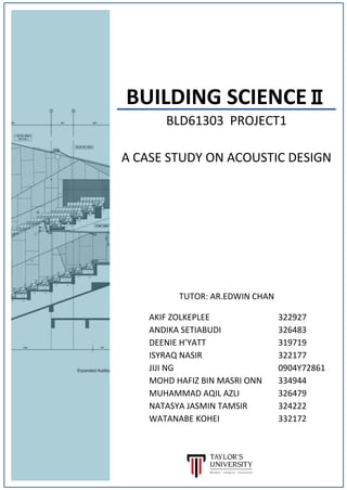
  • 38. 37 Figure 4.5.2.1 Sound delay analysis in DUMC section drawing; to measure the first floor sound delay as it defers in distance Figure 4.5.2.1 Calculations of sound delay for first floor analysis with formula For speech, the longest acceptable delay time is 40ms (14m); music, the longest acceptable delay is 100ms (34m). The first floor area of the auditorium is considered to have acceptable sound delay as from the nearest to the furthest position of seats for its sound delay falls under 30msec. This states that speech can be legible in the auditorium.
  • 39. 38 Figure 4.5.2.1 Sound delay analysis in DUMC ground floor drawing; to measure the ground floor sound delay as to show the reflected sound from the present walls Figure 4.5.2.1 Calculations of sound delay for first floor analysis with formula From here we can see that positions of receiver sits near the end of stage is not the optimum seating area as it have a higher sound delay which affects the speech legibility. However, overall the auditorium allows for clarity in music as sound delay value is below 100msec.
  • 40. 39 4.5.3 SOUND DIFFRACTION AND SOUND DIFFUSION Sound diffracted around the obstacles of the large gaps located at the ceiling surfaces (Figure 4.5.3). Diffusion is even scattering of the sound reflections in the space, by mixing with other propagated sound will resulted in a blending of sound pattern (Figure 4.5.3). The unevenness of surface is bold in scale (Figure 4.5.3), the dimension across these individual surface contours are as greater as the length of the waves that they are intended to diffuse, avoiding the wave reflected as if the surface were flat. This is to increase the high-frequency reflections both to audiences of exposed sitting area and stage players because high-frequency sound is less pronounced since close miking is the recording application. With the sound pressure everywhere the same, the harassed listener would be theoretically incapable of hearing where the sound had come from. So, there should always be enough fall-off away from the source for auditory localisation to the connection with what the listener sees (Figure 4.5.3).
  • 41. 4.5.4 SOUND SHADOW Figure 4.5.4.1. Sound diffraction around large pillars and corners around ground floor resulted as sound shadow area. Sound diffraction occur around large pillars and corners on ground floor of auditorium (Figure 4.5.4.1), and this result in interference among the diffracted waves. These create regions of greater and lesser sound intensity (Figure 4.5.4.1), called sound shadows, after the wave has propagated passed the obstacle. These shaded spaces around the auditorium fail to propagate sound from the stage to the audiences far-off beneath the balcony (Figure 4.5.4.1). Moreover, the extension of the front part of balcony is not risen (Figure 4.5.4.1) so it is not helpful for gathering acoustical energy and reflecting it to the rear. 40
  • 42. 41 Figure 4.5.4.2. The half-polygonal-ring shape of first floor forms the shaded area behind the fan shape of ground floor, which has minimal sound shadow. The arrangement of seats on ground floor is based on the fan shape of ground space, alongside the balcony above designed accordingly to the half-polygonal-ring shape (Figure 4.5.4.2). The volume of space below the balcony is gauged to create a minimal sound shadow effect, by this means to increase that area’s number of far-off audience that can receive more amount of sound.
  • 43. 42 Figure 4.5.5. The flat surface and opening under the balcony has the depth and height of D ≤ 2H. D/H = 5.8 / 3.2 = 1.9 rounded up to 2 The depth of beneath the balcony of this auditorium has been kept equal to twice the height, D ≤ 2H (Figure 4.5.5). In the case of larger volume with greater depth, speech serve to be the function of seating area under the balcony because only clear sound can be reached. Musical instruments generate sounds from 30 Hz to 12,000 Hz which is much broader than the speech spectrum. In that case, musical sound is not evenly distributed under the balcony so the audiences received less reverberation sound during musical performance. 4.5.5 REVERBERATION TIME
  • 44. 43 Approximate reverberation times can be calculated from the Sabine formula: RT = 0.16 A RT = Reverberation Time (Sec) V = Volume of the room (cu.m) A = Total of Absorption of room surfaces ( sq.m sabins) X = Absorption of Coefficient of Air 4.5.5.1 VOLUME OF EXPERIMENTAL AUDITORIUM The reverberant sound in an auditorium dies away with time as the sound is absorbed within more than one interactions with the surfaces of the room. In a extra reflective room, it will take longer for the sound to die away and the room is said to be 'live'. In a very absorbent room, In order to provide a reproducible parameter, a general reverberation time has been described as the time for the sound to die away to a degree 60 decibels beneath its original level. The reverberation time can be modeled to allow an approximate calculation. It is depending on below aspect. Estimated Floor Area (m2 ) A = 12 x 70 = 840 m2 B = 6.6 x 70 = 462 m2 C = 6.1 x70 = 427 m2 D = 7.1 x 70 = 497 m2 E = 9.7 x 70 = 679 m2 Total Volume of Experimental Auditorium: 57m(W) x 25m(L) x 11m(H) = 15675 m3
  • 45. 44 4.5.5.2 AREA OF FLOOR MATERIALS 4.5.5.3 AREA OF WALL MATERIALS
  • 46. 45 Area of wall materials Area of Other Materials
  • 47. 46 4.5.5.4 REVERBERATION TIME CALCULATION RT = 0.16 A Details: RT = Reverberation Time (Sec) V = Volume of the room (cu.m) A = Total of Abs of room surfaces ( sq.m sabins) X = Absorption of Coefficient of Air Total Abs unit = 94.1 + 271 + 1222.2 = 1587.3 m2 sabins Volume area DUMC : 15675 m3 RT = 0.16 ( 15675) = 1.58 secs Desirable reverberation times in a given space
  • 48. 147 5.0 OBSERVATION, DISCUSSION & CONCLUSION 5.1 DISCUSSION ON ACOUSTIC DESIGN There balcony front is made up of flat surfaces that produces long-delay reflections. If the curved or broken or absorptive-treated surfaces are created on the balcony front, the time delay sound can be reduced. Beside that, the area under the balcony needs a larger volume with greater height to increase the reverberation time, with more reflected sound energy allowed till the end. On the balcony soffit, a convex profile on sloping surfaces can help the sound to diffuse instead of reflecting them under the balcony. 5.1 CONCLUSION After going through recordings, observations, documentations and analysis taken; we as a team can conclude that DUMC falls under the category of a mixed acoustical use auditorium in which its acoustical design for speech and performance of music. Despite being a mixed used auditorium, it does not cater well for talks or speeches throughout the whole auditorium without the aid of speakers. Having a speaker for the use of an acoustical design is a statement which can be classified as not a great acoustical response for the auditorium. However, the auditorium do cater for musical performance more than a speech due to the optimal sound echo and reverberation time given for music to perform better even without the aid of speakers. This project enables us to understood the importance of architectural acoustic design and response based on the typology, shape and function of the auditorium. We too had understood how specific adjustments of acoustics are needed to cater of the programmatic demands of an auditorium in general. The analysis made clear the relationship between the acoustic and materials, spatial planning with its surrounding context and certain design principles for what great auditorium has to concern. The understanding at these relationships would greatly benefit us in future design projects as acoustical design response is actually a necessity in our life.
  • 49. 148 6.0 REFERENCES -Reid, E. (n.d.). Understanding buildings a multidisciplinary approach. -Cavanaugh, W., Tocci, G. and Wilkes, J. (2010). Architectural acoustics. Hoboken, N.J.: John Wiley & Sons. -Long, M. (2014). Architectural acoustics. Amsterdam [etc.]: Elsevier Academic Press. -Gupta, S. (n.d.). Introduction to Auditorium Design: Balcony and Ceiling Design. -R. B. Newman, “Acoustics” in J. H. Callender (ed.), Time-Saver Standards for Architectural Design Data, McGraw-Hill, New York, 1974, p. 696. -(2006, May). Retrieved from http://www.industrial-electronics.com/measurement-testing-com/architectual-acous tics-2-SOUND-ABSORPTION-2.html -Groove. (2011, January). Retrieved from http://www.stil-acoustics.co.uk/Timber-Acoustic/Linear.html?COLLCC=2138749363& -Soundsorb « Malaysia Acoustic Ceiling And Wall Panel – E-acoustic Sdn. Bhd. (n.d.). Retrieved from http://www.eacoustic.com.my/our-products/soundsorb/