Introduction of Engineering Graphics
•Descargar como PPTX, PDF•
6 recomendaciones•1,427 vistas

The Introduction of Engineering Graphics...

Recomendados
Más contenido relacionado
La actualidad más candente
La actualidad más candente (20)
Destacado
Destacado (11)
Similar a Introduction of Engineering Graphics
Similar a Introduction of Engineering Graphics (20)
Último
Último (20)
Introduction of Engineering Graphics
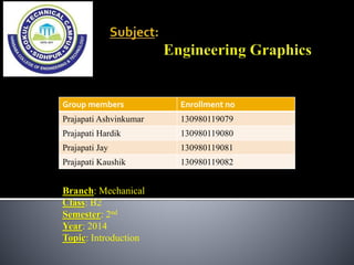
- 1. Group members Enrollment no Prajapati Ashvinkumar 130980119079 Prajapati Hardik 130980119080 Prajapati Jay 130980119081 Prajapati Kaushik 130980119082 Branch: Mechanical Class: B2 Semester: 2nd Year: 2014 Topic: Introduction
- 2. Engineering means “Applied science” Graphics means “drawings” “Language of Engineers” It is a way for communicating Engineer’s ideas, designs and thoughts to others. The communication of ideas through the graphical language. It’s helps to reduce the time, increase the accuracy of the object to be manufacture.
- 3. Freehand drawing The lines are sketched without using instruments other than pencils and erasers. Example
- 4. Instrument drawing Instruments are used to draw straight lines, circles, and curves concisely and accurately. Thus, the drawings are usually made to scale. Example
- 5. Standard Code Country Code Full name India BIS Bureau of Indian Standards USA ANSI American National Standard Institute Japan JIS Japanese Industrial Standard UK BS British Standard Australia AS Australian Standard Germany DIN Deutsches Institut für Normung ISO International Standards Organization
- 6. Drawing Sheet Trimmed paper of a size A0 ~ A4. Standard sheet size (JIS) A4 210 x 297 A3 297 x 420 A2 420 x 594 A1 594 x 841 A0 841 x 1189 A4 A3 A2 A1 (Dimensions in millimeters) A0
- 7. Drawing Scales Length, size Scale is the ratio of the linear dimension of an element of an object shown in the drawing to the real linear dimension of the same element of the object. Size in drawing Actual size :
- 8. Drawing Scales Designation of a scale consists of the word “SCALE” followed by the indication of its ratio, as follow SCALE 1:1 for full size SCALE X:1 for enlargement scales (X > 1) SCALE 1:X for reduction scales (X > 1) Dimension numbers shown in the drawing are correspond to “true size” of the object and they are independent of the scale used in creating that drawing.
- 9. Meaning of Lines Visible lines represent features that can be seen in the current view Hidden lines represent features that can not be seen in the current view Center line represents symmetry, path of motion, centers of circles, axis of axisymmetrical parts Dimension and Extension lines indicate the sizes and location of features on a drawing
- 10. Example : Line conventions in engineering drawing
- 11. Text on engineering drawing is used : To communicate nongraphic information. As a substitute for graphic information, in those instance where text can communicate the needed information more clearly and quickly. Thus, it must be written with Legibility - shape - space between letters and words Uniformity - size - line thickness
- 12. Aligned Dimensioning Unidirectional Dimensioning
- 13. Typical Drawing Equipment Objectives in Drawing 1. Accuracy 2. Speed 3. Legibility 4. Neatness
- 14. It’s a rectangular wooden board 22 mm of thick and size is 650*470 mm
- 15. Working edge Drawing board must be placed on the table with working edge always to be at the left side.
- 16. It’s a combined form of T-square ,Set square Protractors and scale. One end of the drafter is Clamped at the left top end.
- 17. High-quality drawing pencils should be used in technical drawing, never ordinary writing pencils. HB(soft grade) – used for lettering, freehand sketching H ( medium grade ) - used for visible outlines, edges 2H(hard grade) - used for dimension line, hidden line
- 18. The basic principle involved in arriving at the sheet size is x1:x2 = 1:√2 X1,X2 are sides of the sheet The surface area of A0 size sheet is one square meter.
- 21. Standard form of arrangement Important particulars are included Facilitate quick reading of important particulars – quick references are located easily – drawings are prepared at various locations and shared
- 22. space left all around in between the trimmed edges of the sheet a minimum of 10 mm
- 23. Line types
- 24. Dimensions of large objects must be reduced to accommodate on standard size drawing sheet. This reduction creates a scale of that reduction ratio. This ratio is called reducing scale Full scale 1:1 Reducing scale 1:2,1:5,1:10 Enlarging scale 2:1,5:1,10:1
- 25. Point : A point is not a thing, but a place. We indicate the position. Line joining of two point but no breath and think Polygon :it’s a plane figure more than 4 straight lines Depending on the number of sides the regular polygon are classified as 1) Rectangle, 2) Pentagon, 3) Hexagon, 4) Heptagon, 5) Octagon, 6) Nonagon. 3-1024 sides is name as polygon.
- 26. Vertical plane –when the observer is viewing it from the front. It shows only two dimension length and height. Horizontal plane – when the observer is viewing it from top. It shows only breath.
- 30. It’s in first quadrant. Top view comes below to the front view
- 31. It’s in third quadrant Top view comes above the front view