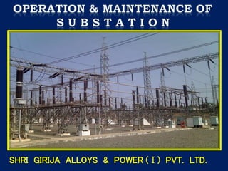
2. The Substation may be defined as assembly of apparatus
which transforms electrical energy from one form to
another, from one voltage to another voltage.
A.C. electrical energy is generated at low voltage but for
transmission the voltage is stepped up. Higher the
voltage, lesser is the current and lesser is the power loss
(I2R) and lesser is the voltage drop (IR). Similarly the
consumers do not use high voltage and so the same must
be stepped down to low voltage. The stepping up and
stepping down of voltage is done in the Substations.
Grid Substation
220/132/33
kV
Distribution
Substation
33/11kV
Generation
11kV
Step-up 220kV Step-down 33kV
4. 1. Low Voltage(LV)Below 1000 Volts
2. Medium Voltage(MV)Below 1000 Volts and
up to 33kV.
3. High Voltage(HV)Above 33kV and up to 132kV
4. Extra High Voltage(EHV)220kV,400kV
5. Ultra High Voltage(UHV)760kV
400kV 220kV 110kV 66kV 33kV 11kV
Span in Mtr. 400 320 320 275 100 120-130
Conductor Moose,
Camel
Drake,
Deer,
Kundha,
Zebra,
Tarantula
Lynx Coyote,
Leopard
Coyote Rabbit
7. FACILITATES BY PASSING A C/B ON LOAD
FAULT ON BUSBAR OR BUSBAR ISOLATOR LEADS TO COMPLETE SHUTDOWN
BUS FAULTS ARE RARE PARTICULARLY WITH RIGID BUSBARS
8.
9. EACH CIRCUIT CAN BE CONNECTED TO EITHER BUS.
CIRCUITS CAN BE SWITCHED ON LOAD.
IF C/B IS TAKEN OUT FOR MAINTENANCE, FEEDER HAS TO BE SHUTDOWN
CAN BE AVOIDED BY PROVIDING A BY-PASS ISOLATOR ON C/B.
USED FOR LARGE GENERATING STATIONS AND GRID SUBSTATIONS
12. BUS TRANSFER BREAKER IS PROVIDED IN ADDITION TO B/C.
C/B TO BE MAINTAINED IS TRANSFERRED TO TRANSFER BUS
WITHOUT AFFECTING OTHER CIRCUITS.
WIDELY USED IN 220 kV AND 400 kV S/S .
13.
14. 3 BREAKERS FOR 2 CIRCUITS.
BOTH BUSES ARE IN SERVICE
A FAULT ON ANY BUS IS CLEARED BY OPENING
ASSOCIATED C/Bs WITHOUT AFFECTING
CONTINUITY OF SUPPLY
ANY C/B CAN BE TAKEN OUT FOR MAINTENANCE
WITHOUT CAUSING INTERRUPTION
ALL LOAD TRANSFER IS BY BREAKERS
EACH BREAKER IS RATED FOR CURRENT OF 2
CIRCUITS
USED FOR 400 kV S/S
15.
16. ONAN - Oil Natural, Air Natural (ForTransformer Cooling)
ONAF - Oil Natural, Air Forced (ForTransformer Cooling)
OFAF - Oil Forced, Air Forced (ForTransformer Cooling)
WTI - WindingTemperature Indicator
OTI - OilTemperature Indicator
PRV - Pressure ReliefValve
OSR - Oil Surge Relay
OLTC - On LoadTap Changer
RTCC - RemoteTap Change Control
MOG - Magnetic Oil level Gauge
IDMT - Inverse Definite MinimumTime (For Relay)
NO - Normally Open Contact
NC - Normally Closed Contact
LILO - Loop In Loop Out (Used for defining Substation)
CRP - Control Relay Panel
TTB - TestTerminal Block
ACDB - A.C. Distribution Board
DCDB - D.C. Distribution Board
MB - Marshalling Box (For Breaker,Transformer control)
AVR - AutomaticVoltage Regulators (ForTap Changing on RTCC )
18. Lightning arrester gives protection to substation
equipments by discharging lightning & switching over
voltages to earth . It consists of a series of spark gaps
and several non-linear resistances like Thyrite , Metrosil
etc.
A non-linear resistor is one whose resistance is not
constant but inversely proportional to applied voltage.
It decreases rapidly as the voltage across it is increased
,i.e. it has an extremely low value when the high surge
voltage appears & allows the flow of heavy currents of
the order of thousands of amperes & dissipates energy
quickly & recovers again, presents a high resistance
value to the normal live voltages soon as surge has
disappeared.
19. Insulator cleaning.
Connection tightness.
Checking of earthing connections.
Reading of leakage currents on daily basis
to be taken. If current shoots in red zone,
then that particular LA is to be replaced as
early as possible.
20.
21. The main tasks of instrument transformers are:
- To transform currents, or voltages, from a high value to a
value easy to handle for relays and instruments.
- To insulate the metering circuit from the primary high voltage.
- To provide possibilities of a standardization, concerning
instruments and relays, of rated currents and voltages.
The current transformer is ideally a short-circuited
transformer where the secondary terminal voltage is
zero and the magnetizing current is negligible.
22. • Window CT :- This is constructed with no
primary winding and is installed around the
primary conductor.
• Bushing CT :- This type of CT specially
constructed to fit around a bushing & it
cannot be accessed.
• Bar CT :- It is window CT but has a
permanent bar installed as a primary
conductor.
• Wound CT :- This CT has a primary &
secondary winding like a normal transformer.
25. “ If CT & protective devices located within same switchgear,5 Amp. secondary
current is used. If CT leads goes out of the switchgear ,1 Amp. secondary
current is preferred.”
CT Core Identification as per Class:-
1. Class 0.2s, 0.5s, 1.0s - Metering core
2. Class 5P10,5P20 - Backup protection core (LBB,O/C & E/F Protection)
3. Class PS - Primary protection core (Differential, Distance ,REF etc.)
Accuracy Limit Factor (ALF) - It is the ratio of largest value of current to CT
rated current up to which CT must retain the specified accuracy.
Example - 5 P20 , 5 VA , ALF = 20
It means when the current is 20 times the rated secondary current, the accuracy
should not exceed 5% at rated burden.
ISF-Instrument Safety Factor for metering core.
26. Checking of Oil level.
Checking the insulation resistance.
Power connection tightness.
Secondary connection tightness.
Cleaning Bushings/Insulators.
Checking proper earthing of body connection.
Checking earthing of CT secondary star points.
28. Description……….
1. Electromagnetic Voltage Transformer:- Its construction largely depends on
the rated primary voltage. Primary & secondary windings are wound on
magnetic core like in usual transformer. For voltages up to 3.3 KV, dry type
transformer with varnish impregnated taped winding is quite satisfactory. For
higher voltages, it is a practice to immerse the core and winding in oil. It is
used up to 66 KV level.
2. Capacitive Voltage Transformer:- For voltages above 66 KV, CVT is used. It
consists of a capacitive potential divider & inductive medium voltage circuit.
Primary voltage is applied to a series capacitor group. The voltage across
intermediate capacitor is taken to primary of auxiliary voltage transformer. The
secondary of auxiliary voltage transformer is taken for measurement or
protection. The inductive part is immersed in oil and sealed with an air
cushion a steel tank. Fuses are provided in secondary box.
29. Checking of oil level & leakage, rectify the same
immediately.
Checking of Insulation Resistance.
Power connection tightness.
Secondary connection tightness.
Check the proper earthing of Body connection.
Check the secondary fuse condition & replace
if required by proper rating.
30. Points to remember……
CT is connected in series with the supply line & PT
is connected across the supply line. The CT
secondary should never be open circuited and no
fuse should be inserted. In a PT the secondary
should never be short-circuited and a fuse is used
in PT secondary circuit.
31. Isolator is the device which makes & breaks circuits in no load condition.
Types of Isolators:
a) Centre Break Rotating Type Isolator.
b) Double Break Rotating Type Isolator.
c) Pantograph Type Isolator.
d) Tandem Isolator.
Earth Switch is provided for safety purpose to work on dead lines
and is electrically & mechanically interlocked with isolators.
34. 1) Checking of the male / female contacts for good condition and proper
Connections.
2) Checking proper alignment of male & female contacts & rectify if required.
3) Cleaning of Insulators & applying petroleum jelly on fixed contact surface.
4) Lubrication of all moving parts on regular basis.
5) Tightness of all earthing connections.
6) In case of Isolator with Earth switch, check electrical and mechanical
interlock i.e. Isolator can be closed only when Earth switch is in open
condition & vice versa.
7) As Isolators are operated on No load, hence check the interlock with
Circuit Breaker, if provided i.e. Isolators can be operated when Breaker is
in OFF condition.
35.
36. Circuit Breaker is used to close or isolate the circuit in
normal and abnormal condition and to protect the
electrical equipment against the fault.
SF6 CIRCUIT BREAKER
38. Low Maintenance compared to other range of
breakers.
Required less space to install (Spring charge
mechanism).
Low resistive losses due to special designs and
material choices.
Low drive energy - replacement of large
hydraulic drives by compact mechanical drives
Minimized SF6 gas leakage rates with special
sealing systems.
39. The Circuit Breakers are classified on the basis
of arc extinction medium :
(A) Bulk Oil type
(B) Minimum Oil type
(C) Air Blast type
(D)Vacuum type
(E) SF6 Gas type
42. A. Bulk Oil Circuit Breaker – Contacts are separated inside a steel tank filled with
transformer oil used for arc quenching.
B. Minimum Oil Circuit Breaker – Contacts are separated in an insulated housing
(interrupter) filled with transformer oil used for arc quenching. In the case of MOCBs
after certain number of tripping, oil is to be replaced as recommended by the
manufacturer. After 2 to 3 times of oil replacement, or after certain numbers of
serious faults, it is necessary to overhaul the complete breaker.
C. Air Blast Circuit Breaker – It utilizes high-pressure compressed air for arc
extinction.
43. D. Vacuum Circuit Breaker – In this breaker, the contacts are housed inside a
permanently sealed vacuum interrupter . The arc is quenched as the contacts are
separated in high vacuum. For VCBs, the vacuum bottle is hermetically sealed
and as such no maintenance is required. However to ascertain the failure of
vacuum bottle, it is necessary to check the contact resistance of each pole or the
travel of each pole as specified by the manufacture. VCBs are generally used up
to 33 KV voltage systems.
E. SF6 Gas Circuit Breaker – Sulphur Hexa Fluoride gas is used for arc
extinction in this breaker. It is must to monitor the SF6 gas pressure inside the
breaker pole and check periodically the contact resistance of each pole or the
travel of each pole. This is helpful to prevent the problem of bursting of poles.
The SF6 breaker has an advantage that the rate of restricting voltage is zero &
hence the burning of male / female contacts is less. SF6 CBs are generally used
for 66kV and above voltage class.
Operating mechanism is of two types: -
I. Movement of contacts is controlled by spring mechanism. (Spring Operated)
II. Movement of contacts is controlled by air pressure. (Pneumatic operated)
44. SF6 Gas:-
High dielectric strength.
Excellent arc quenching ability.
Good thermal conductivity.
Physical & Chemical properties:-
Chemically inert.
Non-toxic
Non-corrosive.
Non-flammable.
Advantages of SF6 Circuit Breaker:-
Very short arcing period.
Can interrupt much larger current compared to other breakers.
No risk of fire.
Low maintenance.
45. Tightness of power connections & control wiring connections.
Cleaning of Insulators.
Lubrication of moving parts.
Checking of contact resistance, close-open timing, Insulation
resistance
Checking of gas pressure for SF6 circuit breaker (leakages if any)
Checking of air pressure for pneumatic operated breaker (leakages if
any)
Checking of Controls, Interlocks & Protections like checking of pole
discrepancy system i.e. whether all three poles are getting ON – OFF
at the same time.
Cleaning of Auxiliary switches by CTC or CRC spray and checking its
operation
46.
47. Transformer essential parts
CONSERVATOR
HV BUSHINGS
LV BUSHINGS
HV WINDING
LV WINDING
MAGNETIC CORE
TANK
RADIATOR
FANS
TRANSIL OIL
RADIATORS
SUPPORTING WHEELS
SILICA GEL
BREATHER
48. Main fixtures of Power Transformer and their functions are listed below: -
a) Buchholz Relay - This relay is designed to detect transformer internal fault in the
initial stage to avoid major breakdown. Internal fault in transformer generates gases
by decomposition of oil due to heat & spark inside the tank. These gases pass upward
towards the conservator tank, trapped in the housing of the relay, there by causing
the oil level to fall. The upper float rotates & switches contacts close & thus giving
alarm.
49. b) Oil Surge Relay - It is similar to Buchholz relay with some changes. It has only one
float & operates when oil surges reach and strike the float of OSR. It is used with
OLTC for detection of any damage or fault inside the tap changer and prevents tap
changer from damages in case of low oil level in OLTC tank.
50. c) Pressure Relief Valve - When the pressure in the tank rises above predetermined
safe limit, this valve operates & performs the following functions: -
1) Allows the pressure to drop by instantaneously opening the port.
2) Gives visual indication of valve operation by raising a flag.
3) Operates a micro switch, which gives trip command to breaker.
Pressure Relief valve
51. d) Conservator - As expansion and contraction occurs in transformer main tank,
consequently the same phenomena takes place in conservator as it is connected to main
tank through a pipe. Conservator communicates with the atmosphere through a breather,
incorporating a dehydrator, which is connected to the breather pipe. Other end of this pipe
opens at the top in the conservator, just below the conservator upper wall.
52. e) Breather - This is a special air filter incorporating a dehydrating material, called, Silica
Gel. It is used to prevent the ingress of moisture and contaminated air into conservator
Silica Gel
Oil Cup
Normal
Blue Colour
Pink Colour,
Reactivation required.
53. f) OIL TEMPRATURE INDICATOR
Oil Temp. Scale
Maximum temp. last reached.
Temp. at present.
Oil Temp. Trip Switch
Oil Temp. Alarm Switch
54. g.) WINDING TEMPRATURE INDICATOR
Winding Temp. Scale
Maximum temp. last reached.
Temp. at present.
S1
S2
S3
S4
Winding Temp. Alarm
Winding Temp. Trip
Group-A Fan Start setting.
Group-B Fan Start setting.
55. TransformerTap
Tapping is provided in Primary winding. Hence by changing the
tapping, we can change secondary voltage as per requirement.
The transformer equation is: - V2/V1 = N2/N1 i.e. V2 = (N2 x V1)/N1
There is an Inverse relationship exists between secondary voltage &
primary turns. When primary turns are decreased i.e. Tap position is
shifted from 3 to 4,secondary voltage gets increased and if primary
turns are increased i.e. Tap position is shifted from 4 to 3, then
secondary voltage gets decreased.
56.
57. Nitrogen Fire Prevention & Extinction System
Nitrogen Storage Unit
Nitrogen Cylinder & mechanism
Nitrogen Gas Injecting
Pipe
Rapid Pressure Rise Relay (RPRR)
58. COMMON FERRULE NUMBERS USED IN WIRINGS
A: CT secondary connection for primary protection like Differential, Distance,
REF Relay). Small “a” used for PT secondary connection in PT terminal box.
B: Bus bar Protection ( CT secondary connection ).
C: Back up Protection (CT secondary connection for O/C & E/F Relay).
D: Metering (CT secondary connection).
E: Metering & Protection (PT secondary connection).
H: A.C. connection.
J: D.C. connection (Before Fuse).
K: D.C. connection for control (After Fuse).
L: D.C. connection for Indication (After Fuse).
M: Motor Supply (Spring charging Motor in Circuit Breaker).
N: RTCC (Tap Changer) connection. Also for denoting A.C. Neutral connection.
P: PT primary connection & DC circuit of Bus bar protection scheme.
R: R Phase Indication.
S: CT secondary connection inTerminal Box.
U: Circuit Breaker auxiliary contacts.
X: TB Numbering.
Y: Y Phase Indication.
59. Some Important Numbers used with their meanings
2: Time Delay Relay or Timer
21: Distance Protection Relay
27: Under Voltage Relay
49: Winding Temperature Indicator
50/51: IDMT Over Current Relay with Instantaneous element
50/51N: IDMT Earth Fault Relay with Instantaneous element
52: AC Circuit Breaker
59: Over Voltage Relay
62: Pole Discrepancy Relay with timer
63: Gas Operated Relay (Buchholz Relay)
64R: Restricted Earth Fault Relay
67: Directional Over Current Relay
67N: Directional Earth Fault Relay
75: P.T. selection Relay
80: DC Supervision Relay
86: Master Trip / Locking Out Relay
87: Differential Relay
89: Line Switch / Isolator (Electrically Operated)
94: Anti-pumping Relay (For Breaker Control)
95: Trip Circuit Supervision Relay
96: Gas Pressure Relay (For Breaker Control)
60. Visual checking ofTransformer
Check the colour of silica gel. If it is pink, reactivate or replace it. Also
ensure proper quantity of oil in breather oil cup.
Check oil level in Conservator of Main Tank & OLTC. It should be > ½ level
marking.
Check oil level in Bushings.
Check for any oil leakage. Arrest leakages, if any.
Check the working of OTI & WTI by taking hourly temperature readings.
There should be changes in readings as per loading of transformer and
atmospheric condition.
Check the cooling system by making fans / pumps operation by manually.
Check the tap position of RTCC panel and OLTC panel. It should have same
position number.
Check the humming noise & vibration of transformer. If any abnormality
found, it is to be referred to concerned manufacturer.
61. Red - Phase connection, either directly connected to the primary circuit
or Connected to secondary circuit of CT and PT.
Yellow - Phase connection, either directly connected to the primary
circuit or Connected to secondary circuit of CT and PT.
Blue - Phase connection, either directly connected to the primary circuit
or Connected to secondary circuit of CT and PT.
Black - A.C. neutral connection, Star point connections of secondary
circuit of CT and PT, and connections in A.C. and D.C. circuit.
Green - Connections to earth
Grey - Connections in D.C.circuit
Each wire should have a letter to denote its function. D.C. supply
from +ve source should bear odd number & from -ve source should
bear even number.
CT Secondary Terminal – S2 of all protection & metering cores are
shorted in CT junction box. Only one common wire of S2 along with
S1 wires of all 3 phases CTs are brought to CRP. Earthing of S2
wires is done at one end. (preferably at CRP end).
66. P L C C
* PLCC EQUIPMENT IS USED FOR POINT TO
POINT COMMUNICATION OVER HIGH VOLTAGE
LINES.
* IT IS USED FOR TRANSMISSION OF SPEECH /
DATA / TELEPROTECTION SIGNALS BY USING
HF CARRIER SIGNAL RANGE FROM 50 TO 500
KHZ.
* PLCC IS DUPLEX TYPE OF COMMUNICATION.
67. In substation, various drawings are available namely:
(A) Wiring Drawing : The routing of wires from various equipments
in a control and relay panel is shown in this drawing. The route of
the particular wire as per its purpose of application can be traced
easily while attending any faults in the particular circuit.
For reading of drawing it should be kept in mind that drawing is
prepared when isolator & breaker positions are OFF & spring of the
breaker mechanism is in deenergised condition.
(B) Schematic Drawing : This drawing is a representation of various
circuits such as metering, protection, control, indication,
annunciation, etc. in a control and relay panels.
(C) Layout Drawing : This drawing shows arrangement of various
indoor and outdoor equipments in a particular installation in a
sequential order.
69. Sequence to be followed as mentioned below:-
a) First ensure that breaker of auxiliary bay is in OFF condition.
b) Close Isolators 89 A and 89 C of auxiliary bay.
c) Now close the Isolator 89 C of transformer bay.
d) Put control switch of transformer control panel on Intermediate position.
e) Close the auxiliary bay breaker.
f) Put Off the Transformer bay breaker. Put control switch on Transfer position.
Now auxiliary bay breaker will control all protections of transformer.
g) Open Isolators 89 A and 89 L of transformer bay. Carry out maintenance of
transformer bay breaker by taking shutdown permit & do the maintenance
as per safety practices.
70. a) Remove all tools & tackles. Also remove temporary earthing if provided
from working place. Return shutdown permit.
b) Close Isolators 89 A and 89 L of transformer bay.
c) Put control switch of transformer control panel on Intermediate position.
d) Close the transformer bay breaker.
e) Now open the auxiliary bay breaker. Then control switch is to be kept on
normal position as original.
f) Open Isolators 89 C of transformer bay.
g) Open Isolators 89 A and 89 C of auxiliary bay. Now auxiliary bay is dead.