23-Design of Column Base Plates (Steel Structural Design & Prof. Shehab Mourad)
•
9 recomendaciones•4,429 vistas

23-Design of Column Base Plates (Steel Structural Design & Prof. Shehab Mourad)

Recomendados
Recomendados
Más contenido relacionado
La actualidad más candente
La actualidad más candente (20)
Similar a 23-Design of Column Base Plates (Steel Structural Design & Prof. Shehab Mourad)
Similar a 23-Design of Column Base Plates (Steel Structural Design & Prof. Shehab Mourad) (20)
Más de Hossam Shafiq II
Más de Hossam Shafiq II (20)
Último
Último (20)
23-Design of Column Base Plates (Steel Structural Design & Prof. Shehab Mourad)
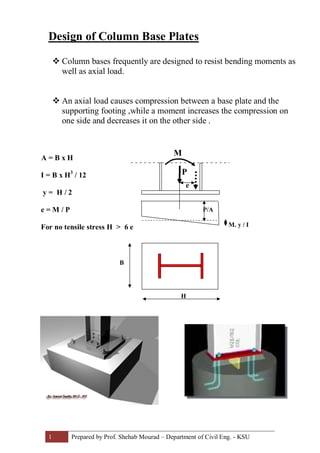
- 1. 1 Prepared by Prof. Shehab Mourad – Department of Civil Eng. - KSU Design of Column Base Plates v Column bases frequently are designed to resist bending moments as well as axial load. v An axial load causes compression between a base plate and the supporting footing ,while a moment increases the compression on one side and decreases it on the other side . A = B x H I = B x H3 / 12 y = H / 2 e = M / P For no tensile stress H > 6 e M P P/A M. y / I B H e
- 2. 2 Prepared by Prof. Shehab Mourad – Department of Civil Eng. - KSU v for small moment the forces may be transferred to the footing through flexure of the base plate. v For higher moments ,stiffened or booted connections may be used Design requirements: 1- Choose a base plate dimension ( H x B) so that the maximum compression stress should not exceed the maximum bearing stress on concrete fc fb = 0.60 x 1.7 f 'c , where f 'c = compressive strength of concrete 2- Thickness of base plate t ³ Where; M pu = moment acting at base plate at center of compression flange fb = 0.90 6 M p u fb Fy
- 3. 3 Prepared by Prof. Shehab Mourad – Department of Civil Eng. - KSU Example : Design a moment resisting base plate to support a W 530 x 150 column with an axial load of Pu = 1735 kN and bending moment Mu = 200 kN.m. Use A36 steel with Fy = 250 MPa and concrete footing strength = 35 MPa. Solution For W530x150 , d = 543 mm , tw = 12.7mm , bf = 312 mm , tf =20.3 mm Eccentricity , e = (Mu x1000) /Pu = (200x 1000) / 1735 = 115.27 mm For no tensile stress on base plate, H ³ 6 e = 6 x 115.27 mm = 691.6 mm Then choose H = 750 mm and B = 500 mm Check stresses on concrete footing f = - Pu / A ± Mu .y / I = - 1735 x 103 / ( 750 x 500) ± 200 x 106 x 375 / (500 x 7503 /12) f = - 4.60 ± 4.30 f max = -8.90 MPa < fc Pu = 0.6 x 1.7 x 35 = 35.7 MPa O.K f min = -0.30 MPa ( still compression) O.K taking moments at center of compression flange per unit width (sec I-I) M pu I-I = ( 7.60 x 113.65 2 / 2 ) + (8.90-7.60) (113.65 2 ) /3 = 54679 N.mm t ³ = ( 6 x 54679/ 0.9x 250) 0.5 = 38.20 mm Choose t = 40 mm checking bending in transverse direction (sec II-II) /2 = 125.2 mmx = ( 500 – 0.8 x 312) Average stress f = (0.3+8.9)/2 = 4.6 MPa Mpu II-II = (4.60) (125.2)2 /2 = 36053 N.mm < 54679 N.mm (O.K) Use base plate 750mm x 500 mm x 40mm 6 M p u fb Fy B = 500 H = 750 d = 543 103.5103.5 113.65 -8.90 -0.30 -7.60 x x I I IIII