Lec13 Continuous Beams and One Way Slabs(3) Footings (Reinforced Concrete Design I & Prof. Abdelhamid Charif)
•
6 recomendaciones•1,536 vistas

Lec13 Continuous Beams and One Way Slabs(3) Footings (Reinforced Concrete Design I & Prof. Abdelhamid Charif)

Recomendados
Recomendados
Más contenido relacionado
La actualidad más candente
La actualidad más candente (20)
Similar a Lec13 Continuous Beams and One Way Slabs(3) Footings (Reinforced Concrete Design I & Prof. Abdelhamid Charif)
Similar a Lec13 Continuous Beams and One Way Slabs(3) Footings (Reinforced Concrete Design I & Prof. Abdelhamid Charif) (20)
Más de Hossam Shafiq II
Más de Hossam Shafiq II (20)
Último
Último (20)
Lec13 Continuous Beams and One Way Slabs(3) Footings (Reinforced Concrete Design I & Prof. Abdelhamid Charif)
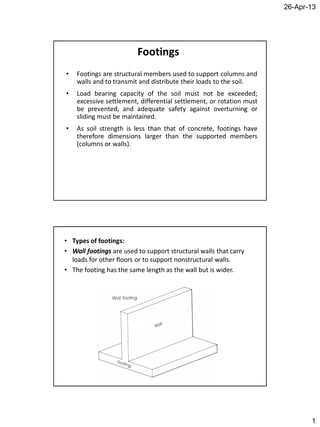
- 1. 26-Apr-13 1 Footings • Footings are structural members used to support columns and walls and to transmit and distribute their loads to the soil. • Load bearing capacity of the soil must not be exceeded; excessive settlement, differential settlement, or rotation must be prevented, and adequate safety against overturning or sliding must be maintained. • As soil strength is less than that of concrete, footings have therefore dimensions larger than the supported members (columns or walls). • Types of footings: • Wall footings are used to support structural walls that carry loads for other floors or to support nonstructural walls. • The footing has the same length as the wall but is wider.
- 2. 26-Apr-13 2 Isolated / single / spread footings support single columns. This is one of the most economical types of footings and is used when columns are spaced at relatively long distances Combined footings usually support two or three columns in a row. Combined footings are used when tow columns are so close that single footings cannot be used or when one column is located at or near a property line
- 3. 26-Apr-13 3 Cantilever or strap footings consist of two single footings connected with a beam or a strap and support two single columns. This type replaces a combined footing and is more economical Continuous footings support a row of three or more columns. They have limited width and continue under all columns.
- 4. 26-Apr-13 4 Rafted or mat foundation consists of one footing usually placed under the entire building area. They are used, when soil bearing capacity is low or column loads are heavy. Pile caps are thick slabs used to tie a group of piles together to support and transmit column loads to the piles.
- 5. 26-Apr-13 5 Distribution of Soil Pressure When the column load P is applied on the centroid of the footing, a uniform pressure is assumed to develop on the soil surface below the footing area. However the actual distribution of the soil is not uniform, but depends on may factors especially the composition of the soil and degree of flexibility of the footing. Distribution of Soil Pressure
- 6. 26-Apr-13 6 Combined loading (axial force and bending moment) For a square footing with width L, total soil pressure is given by: e is the eccentricity: To avoid tension in the soil the equivalent eccentric load must be applied within the kern: L e L P L M L P I My A P q 6 1 6 232 max P M e 6 L e Spread footing under compression force only A footing is usually subjected to column load, its self weight, the weight of the soil above as well as a possible top surcharge such as ground slab and its load. This loading is uniform apart from column load P.
- 7. 26-Apr-13 7 Total soil pressure is: The pressure causing bending in the footing is caused by the concentrated force P only. It is therefore convenient to compute the net soil pressure as: 0qhh A P q ss A P qhhqq ssn 0 Footing analysis and design Footings must be designed to carry the column loads and transmit them to the soil safely while satisfying code limitations. Footing dimensions are based on allowable soil bearing capacity using service loads: RC design of footings uses ultimate loads: LDLiveDead PPPPP LDu PPP 7.14.1
- 8. 26-Apr-13 8 Analysis and design steps • 1- Footing area (dimensions) • 2- Check thickness for one and two way shear • 3- RC design of footing • In step 1, we use net allowable pressure and service load P • In steps 2 and 3, we use net ultimate pressure Minimum footing area (dimensions) Net soil pressure must not exceed the net allowable soil pressure: The net allowable soil pressure is deduced from the allowable soil pressure as: Minimum footing area is therefore: The adopted footing area must be equal or greater than nan q A P q na LD na q PP q P A min 0qhhqq ssana minA
- 9. 26-Apr-13 9 Strength requirements • For strength requirements (shear and bending), net ultimate soil pressure is used. • The net ultimate pressure is obtained using ultimate axial force and actual adopted footing area. • L1 and L2 are the final adopted footing dimensions 21LL P A P q uu nu Shear strength • The spread footing supporting a single column acts like a two- way slab panel (flat plate) for an interior column. • Both one-way and two-way shear must be checked. • We must check in both cases that: uc VV
- 10. 26-Apr-13 10 Two-way shear Assume a value for average steel depth d Usually: d = h – 100 (mm) Determine critical perimeter length b0 For rectangular columns of sides c1 and c2 b0 = 2(c1+d) +2(c2+d) = 2(c1 + c2 + 2d) For square columns where one side = c b0 = 4(c + d) Ultimate two-way shear • The ultimate shear is computed over the loaded area defined as the total footing area minus the critical area: • Rectangular column: • Square column: dcdcLLqAAqV nucnuu 21210 dcdcqPV nuuu 21 2 dcqPV nuuu
- 11. 26-Apr-13 11 Nominal two-way shear )3( 3 )2( 12 2 )1( 6 2 1 0 ' 0 ' 0 0 ' db f db f b d db f MinV c cs c c c side)short/side(longratioaspectcolumn:c column)(interior40s One-way shear For footings with bending action in one direction the critical section is located a distance d from column face Ultimate shear force at section m-m: d cL LqV 22 1 2nuu dL f V c c 2 ' 6 Nominal one-way shear strength:
- 12. 26-Apr-13 12 Flexural Strength and Footing reinforcement The footing is modeled as a double cantilever beam subjected to uniform load as shown. The maximum ultimate moment is located at the column face section n-n RC design is performed using this moment value. 8 )( 2 2 2 1 2 2 1 cL Lq cL wM nuuu Example 1: Square spread footing Design a square spread footing supporting a square column with section 450x450, transmitting a service dead axial load of 1780 kN and a service live axial load of 1200 kN. The buried footing supports a 150 mm thick top soil layer with unit weight of 19 kN/m3 and a 150 mm thick ground slab subjected to a loading of 4.5 kN/m2.
- 13. 26-Apr-13 13 • RC Material data: • Soil allowable bearing capacity is: • • The service axial loads are: • The net allowable soil pressure is: • Soil unit weight is: • The top surcharge q0 is composed of the ground slab weight and its loading: 2 0 /1.85.4150.024 mkNxq MPafc 25' 3 /24 mkNc MPafy 420 2 /300 mkNqa kNPD 0.1780 kNPL 0.1200 0qhhqq sscana 3 /19 mkNs Footing thickness Footing thickness h is estimated as varying between one to two times the dimension of the column section: Thus: We choose an initial thickness of 800 mm. The net allowable soil pressure is then: chc 20.1 900450 h 2 /85.2691.8150.019800.0240.300 mkNqna
- 14. 26-Apr-13 14 The required footing area must satisfy: For a square footing, the length must satisfy: We take L = 3.4 m. Net ultimate soil pressure is: Before performing RC design, we must check the footing thickness with respect to shear. 2 053.11 85.269 12001780 m q PP A na LD mL 323.3 2 /04.392 56.11 0.4532 4.34.3 7.14.1 mkN PP A P q LDu nu The average steel depth is estimated as: Two way shear check The footing with the column is similar to a flat plate with an interior column. The critical perimeter dimensions are: The critical perimeter length is: mmhhhd 700100800100257525cover mmdcppp 115070045021 mmpb 46001150440
- 15. 26-Apr-13 15 3.4 m 3.4 m1150 1150 3.4 m 3.4 m450 450 Ultimate shear is computed over the loaded area defined as the total footing area minus the critical area: kN ppLLqAAqV nucnuu 5.401315.115.14.34.304.392 21210 For two-way shear, concrete nominal shear strength is given by the minimum of equations (1) to (3) : column)(Internal40)3( 3 0.1 450 450 )2( 12 2 4600700)1( 6 2 1 Min 0 ' 0 ' 0 00 ' s c c cs c c c db f db f b d mmbmmddb f V kNV kNN kNN kNN V cc 67.5366 67.536667.53666667004600 3 25 0.10850108500007004600 12 25 4600 70040 2 0.805080500007004600 6 25 1 2 1 Min kNVkNV uc 5.40130.402567.536675.0 Two-way shear is thus OK
- 16. 26-Apr-13 16 One-way shear check 3.4 3.4m d p md cL p 775.07.0 2 45.0 2 4.3 22 The ultimate shear given by the shaded loaded area is: kN pLqV nuu 0.1033 4.3775.004.392 For one-way shear, concrete nominal shear strength is: kNNdL f V c c 67.991667.99166667003400 6 25 6 2 ' kNVc 5.743767.991675.0 It is much greater than Vu. One-way shear is thus also OK RC Design wu = qnu x 3.4 3.4m f 0.45 3.4 3.4m f The ultimate moment at the fixed end is: mkN cL Lq f wM nuuu .0.1450 8 )45.04.3( 4.304.392 8 )( 2 222
- 17. 26-Apr-13 17 RC design of a rectangular section with dimensions: b = 3.4 m = 3400 mm h = 800 mm Steel depth: d = h – cover – 25 = 800 – 75 – 25 = 700 mm We find the required steel ratio: Required steel area is: As = 5610.6 mm 2 Minimum steel Asmin = 0.0018bh = 0.0018 x 3400 x 800 = 4896.0 mm 2 We use eighteen 20-mm bars (5654.87 mm 2) in both directions. This bottom reinforcement must be distributed across the entire footing width. 0023574.0 Dowel bars At least four column corner bars (called dowel bars) must be extended into the footing, bent at the ends, and tied to the main footing reinforcement. The dowel diameter shall not exceed the diameter of the longitudinal bars in the column by more than 4 mm.
- 18. 26-Apr-13 18 Example 2: Wall (strip) footing Design a strip footing supporting a 300-mm thick wall transmitting a service dead axial load of 145 kN/m and a service live axial load of 180 kN/m. The buried footing supports a 1.5 m thick top soil layer with unit weight of 18 kN/m3. We analyze and design 1-m strip. RC Material data: Soil allowable bearing capacity is: The service axial loads are: The net allowable soil pressure is: Soil unit weight is: There is no top surcharge: q0 = 0 Footing thickness estimated as varying between one to one and half times the dimension of the wall width. We use: h = 400 mm MPafc 25' 3 /24 mkNc MPafy 420 2 /240 mkNqa kNPD 0.145 kNPL 0.180 0qhhqq sscana 3 /18 mkNs 450300 h
- 19. 26-Apr-13 19 The net allowable soil pressure is then: 2 /4.2035.1184.024240 mkNqna Minimum footing area (for 1-m strip): Thus: We use: L = 1.6 m Net ultimate soil pressure is: Before performing RC design, we must check the footing thickness with respect to shear. For wall footings, only one-way (beam) shear has to be checked. 2 minmin 598.1 4.203 180145 1 m q PP LA na LD mL 598.1min 2 /125.318 0.16.1 1807.11454.1 mkN A P q u nu One-way shear check The ultimate shear given by the shaded loaded area is: For one-way shear, concrete nominal shear strength is: It is greater than Vu. One-way shear is thus OK 1.6 1.0 m d p md wL p 335.0315.0 2 3.0 6.1 22 kNpLqV nuu 6.1060.1335.0125.3182 kNNdb f V w c c 5.2622625003151000 6 25 6 ' kNVc 875.1965.26275.0
- 20. 26-Apr-13 20 RC Design Footing modeled as double cantilever Ultimate moment at fixed end is: wu =qnu x 1.0 1.6 m f 0.30 mkNx f wM uu .2.67 8 )3.06.1( 0.1125.318 2 22 RC design of a rectangular section with dimensions: b = 1.0 m = 1000 mm h = 400 mm Steel depth: d = 315 mm We find: As = 574.6 mm2 Asmin = 0.0018bh = 0.0018 x 1000 x 400 = 720.0 mm2 We thus use minimum steel area This requires four 16-mm bars (per meter), spacing = 250 mm Provide shrinkage steel in longitudinal direction Example 3: Restricted spread footing Design a restricted spread footing supporting a square column 450 x 450 mm, transmitting a service dead axial load of 1100 kN and a service live axial load of 900 kN. The buried footing supports a 1.2 m thick top soil layer with unit weight of 18 kN/m3. The footing width is restricted to 2.5 m Material data: MPafc 25' 3 /24 mkNc MPafy 420 2 /240 mkNqa Choose footing depth h = 700 mm 3 /18 mkNs Net allowable soil pressure is: 0qhhqq sscana 2 /6.2012.1187.024240 mkNqna There is no top surcharge: q0 = 0
- 21. 26-Apr-13 21 The required footing area must satisfy: Footing width limited to 2.5 m Minimum footing length is then: We use: Net ultimate soil pressure is: Before performing RC design, we must check the footing thickness with respect to shear. 2 29.9 6.201 9001100 m q PP A na LD mL 97.3 5.2 29.9 1 2 /0.307 0.10 0.3070 5.20.4 7.14.1 mkN x PP A P q LDu nu mL 5.22 mL 0.41 The average steel depth is estimated as: Two way shear check The footing with the column is similar to a flat plate with an interior column. The critical perimeter dimensions are: The critical perimeter length is: mmhhhd 600100700100257525cover mmdcppp 105060045021 mmpb 42001050440
- 22. 26-Apr-13 22 Ultimate shear is computed over the loaded area defined as the total footing area minus the critical area: kN ppLLqAAqV nucnuu 53.273105.105.15.20.40.307 21210 For two-way shear, the concrete nominal shear strength is given by the minimum of equations (1) to (3) column)(Internal40)3( 3 0.1 450 450 )2( 12 2 4200600)1( 6 2 1 Min 0 ' 0 ' 0 00 ' s c c cs c c c db f db f b d mmbmmddb f V kNV kNN kNN kNN V cc 0.4200 0.42000.42000006004200 3 25 0.8100810000006004200 12 25 4200 60040 2 0.630063000006004200 6 25 1 2 1 Min kNVkNV uc 53.27310.31500.420075.0 Two-way shear is thus OK
- 23. 26-Apr-13 23 One-way shear check 4.0 2.5m d p md cL p 175.16.0 2 45.0 2 0.4 22 1 The ultimate shear given by the shaded loaded area is: kN pLqV nuu 8.901 5.2175.10.3072 For one-way shear, concrete nominal shear strength is: kNNdL f V c c 0.125012500006002500 6 25 6 2 ' kNVc 5.9370.125075.0 It is greater than Vu. One-way shear is thus also OK RC Design Design must be performed in both directions wu =qnu x 2.5 4.0m f 0.45 4.0 2.5m f The ultimate moment at the fixed end is: mkN cL Lq f wM nuuu .05.1209 8 )45.00.4( 5.20.307 8 )( 2 22 1 2 2 RC design in long direction
- 24. 26-Apr-13 24 RC design of a rectangular section with dimensions: b = 2.5 m = 2500 mm h = 700 mm Steel depth: d = h – cover – 25 = 700 – 75 – 25 = 600 mm Required steel area is: As = 5532.6 mm 2 Minimum steel Asmin = 0.0018bh = 0.0018 x 2500 x 700 = 3150.0 mm 2 We use eighteen 20-mm bars (5654.87 mm 2) Corresponding spacing S = 139 mm = 2500/18 The ultimate moment at the fixed end is: mkN cL Lq f wM nuuu .08.645 8 )45.05.2( 0.40.307 8 )( 2 22 2 1 2 RC design in short direction wu =qnu x 4.0 2.5m f 0.45 2.5 4.0m f
- 25. 26-Apr-13 25 RC design of a rectangular section with dimensions: b = 4.0 m = 4000 mm h = 700 mm Steel depth: d = h – cover – 25 = 700 – 75 – 25 = 600 mm Required steel area is: As = 2878.4 mm 2 Minimum steel Asmin = 0.0018bh = 0.0018 x 4000 x 700 = 5040.0 mm 2 We use seventeen 20-mm bars (5340.7 mm 2) Corresponding spacing S = 235 mm = 4000/17