Analytical Measurements: Troubleshooting, Maintenance and the Future
•Descargar como PPT, PDF•
11 recomendaciones•7,049 vistas

Focuses on measurement of pH, ORP (Redox), and Conductivity and aspects related to inline measurement of these critical analytical parameters. Discussion topics include scientific theory, measurement challenges, proper troubleshooting, installation, key applications, and the future of analytical measurements
![What is pH ? ,[object Object],[object Object]](data:image/gif;base64,R0lGODlhAQABAIAAAAAAAP///yH5BAEAAAAALAAAAAABAAEAAAIBRAA7)
Recomendados
Más contenido relacionado
La actualidad más candente
La actualidad más candente (20)
Destacado
Destacado (20)
Similar a Analytical Measurements: Troubleshooting, Maintenance and the Future
Similar a Analytical Measurements: Troubleshooting, Maintenance and the Future (20)
Último
Último (20)
Analytical Measurements: Troubleshooting, Maintenance and the Future
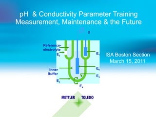
- 1. pH & Conductivity Parameter Training Measurement, Maintenance & the Future ISA Boston Section March 15, 2011 U E 2 E 3 E 1 Reference- electrolyte E 6 E 5 E 4 Inner Buffer
- 3. Definition: pH = - log [a H+ ] H 2 0 H + + OH - [ a H+ ] * [ a OH- ] / [a H2O ] = 10 -14 0 1 2 3 4 5 6 7 8 9 10 11 12 13 14 pH acidic: pH 0-6.9 [H + ] > [OH - ] [H + ] > 10 -7 M neutral: pH 7.0 [H + ] = [OH - ] [H + ]= 10 -7 M alkaline: pH 7.1 - 14 [H + ] < [OH - ] [H + ] < 10 -7 M pH basics - pH scale
- 4. Some examples of pH values 0 1 2 3 4 5 6 7 8 9 10 11 12 13 14 lemon juice orange juice beer cheese milk pure water egg white borax Milk of Magnesia H 2 SO 4 (1N) 4.9% HCl (0.1N) 0.37% acetic acid (0.1N) 0.6% HCN (0.1N) 0.27% sodium bicarbonate 0.84% (0.1N) potassium ac. 0.98% (0.1N) NH 4 OH 0.017% (0.01N) NH 4 OH 1.7% 1.0N NaOH 4%
- 5. How does pH measurement work? pH is a potentiometric measurement via an electrochemical sensor/electrode/probe U= E pH -E ref (mV) This potential difference is a function of the solution being measured E pH glass electrode E ref reference electrode high impedance pH Meter
- 7. What is special about pH glass? H + H + + + + + + + - - - - - - Acidic Alkaline Glass membrane Glass membrane (0.2 - 0.5mm) Gel layer ca. 1 µm (outer and inner) positive charge negative charge internal buffer The surface layer of the glass membrane is the “key performer” in each pH measurement! pH is a measurement of the potential difference between inner and outer layer of glass membrane! This is one reason why pH sensors need to be stored in salt solution when not in use!
- 10. The Nernst Equation E = E 0 + 2.303 R T log n F 1. Internal Reference Potential 2. Inner Glass/Solution Potential 3. External Reference Potential 4. LIQUID JUNCTION POTENTIAL
- 11. The Nernst Equation E = E 0 + 2.303 R T log n F 2.303 R T is known as “The Electrode Slope” n F IDEAL SLOPE = 59.16 mV/pH unit at 25 °C Slope is temperature dependent
- 12. The Nernst Response Curve mV = 59.16 pH mV E = E o + 2.3 RT/F log a H + where 2.3 RT/F = 0.198T K = 59.16 mV @ 25 o C
- 13. pH Electrode Calibration Curve pH 0 4 7 10 14 + 500 mv 0 mv - 500 mv millivolts pH 10.00 buffer 0.0 millivolts pH 7.00 buffer -177.5 millivolts IDEAL VALUES!
- 15. Temperature Error (No Temp. Compensation) Temperature error table for pH signal pH °C 2 3 4 5 6 7 8 9 10 11 12 5 0.30 0.24 0.18 0.12 0.06 0 0.06 0.12 0.18 0.24 0.30 15 0.15 0.12 0.09 0.06 0.03 0 0.03 0.06 0.09 0.12 0.15 25 0 0 0 0 0 0 0 0 0 0 0 35 0.15 0.12 0.09 0.06 0.03 0 0.03 0.06 0.09 0.12 0.15 45 0.30 0.24 0.18 0.12 0.06 0 0.06 0.12 0.18 0.24 0.30 55 0.45 0.36 0.27 0.18 0.09 0 0.09 0.18 0.27 0.36 0.45 65 0.60 0.48 0.36 0.24 0.12 0 0.12 0.24 0.35 0.48 0.60 75 0.75 0.60 0.45 0.30 0.15 0 0.15 0.30 0.45 0.60 0.75 85 0.90 0.72 0.54 0.36 0.18 0 0.18 0.36 0.54 0.72 0.90 No temperature error Temperature error < 0.1 pH units Temperature error > 0.1 but < 0.3 pH units Temperature error = or > 0.3 pH units ( simplified model with Error = /pH (pr.) - 7/ x /(T (pr.) - 25):10/ x 0.03 )
- 20. pH Calibration /Justification 1. Step Determine Asymmetry Potential / Zero Point 2. Step Determine the Slope pH Buffer 7.00 pH Buffer 4.00 [mV] 200 -200 pH 7 14 [mV] 200 -200 pH 7 14 pH as 4 [%] Slope
- 34. Questions?
- 36. Conductivity Measurement A conductivity “cell”, sensor, or electrode is an “electro-mechanical” measurement 1 cm 1 cm d = 1 cm Cond Solution Electrode plate VAC
- 45. Cell Geometry The measured resistance will be dependent on the spacing of the electrode – cell geometry “cell constant” Therefore, units measurement has dimension component, ex. mS/cm 1 cm 1 cm d = 1 cm Cond Solution Electrode plate VAC
- 46. Measuring Conductivity ~ H H O Na + Cl - H + O H -
- 50. Conductivity Temperature Effects ~ H + H H O O H - Na + Cl - H + O H - Na + Cl -
- 52. Sensor Cell Constant 0.1 cm 0.1 cm -1 0.1 cm 1 cm Conductivity Cell Constant = Length Area 1 cm 1 cm 2 = = 1 cm -1 INSULATOR ELECTRODE ELECTRODE INNER OUTER 1 cm 1 cm
- 57. Four-Electrode Conductivity Measurement AC Current Source AC Voltage Measurement Drive Electrodes Measuring Electrodes Four Electrode Sensor Four-Electrode Measuring Instrument
- 63. Cell Installation -2 electrode NOT Recommended Cell Installation... INLET OUTLET OUTLET AIR INLET Avoid dead legs and air traps
- 64. Cell Installation -4 electrode Recommended OUTLET INLET Maintain a minimum clearance between sensor and pipe
- 65. Cell Installation -4 electrode NOT Recommended Maintain a minimum clearance between sensor and pipe
- 66. Conductivity, Resistivity, TDS Ranges Conductivity 100M 10M 1M 100K 10K 1K 100 10 1 Ultrapure water Deionized water Distilled water Condensate Drinking water Cooling tower water Percentage of acids, bases and salt Waste water Brackish water, Sea water Water for Industrial Process 5% Salinity 2% NaOH 20% HCl 0.01 .1 1 10 100 1000 10k 100k 1000k 0.021 0.4 4.6 46 460 4.6k 46k TDS ppm Conductivity and resistivity are measured at 25 C; TDS is expressed as Sodium Chloride (NaCl) Resistivity ohm-cm µS-cm
- 67. Main Applications and Measuring Range Inductive 4 Elec 2 Elec 0.01 0.1 1.0 10 100 1000 10k 100k 1000k Conductivity ( µ S/cm) 100 M 10M 1M 100k 10k 1000 100 10 1 Resistivity (Ohm-cm) Ultra pure water Pure water Make up water Drinking water Diluted acids, bases, salts Waste water Brackish water Industrial process water Acids, bases Water Processes Biotech/Food and Beverage Chemical Processes
- 68. So….where is analytical measurement today?
- 69. Previous Analog Technology Digital technology provides better sound quality
- 70. Welcome to the Digital World! Same electrochemical end of the sensor converted to digital signal which is more robust and gives more information
- 71. Analog Sensor Technology Most analog sensors provide the user with one piece of information to determine the health of the sensor: Slope Limited information for troubleshooting
- 77. Applications and Measurement Range Expanded range with enhanced accuracy! 0.01 0.1 1.0 10 100 1000 10k 100k 1000k Conductivity ( µ S/cm) 100 M 10M 1M 100k 10k 1000 100 10 1 Resistivity (Ohm-cm) Ultra pure water Pure water Make up water Drinking water Diluted acids, bases, salts Waste water Brackish water Industrial process water Acids, bases CURRENT 4E RANGE CURRENT 2E RANGE UniCond ® extends the range of measurement to cover UPW to seawater with a single sensor! UPW to seawater with a single UniCond ® sensor !
- 79. Questions?
Notas del editor
- Some examples are: Beer 4,5 pH Milk 6,2 pH lemon juice 2,2 pH HCl 0,1 M 1 pH Activity a= concentration* activity factor. This activity factor is often estimated to be close to 1, and means activity~concentration
- Describe reference system. Calomel reference (Hg/Hg 2 Cl 2 ) is the general electrochemical standard in place of the standard hydrogen electrode (describe!). Not suitable for industrial use: unstable above 60 o C toxic Preferred system is Ag/AgCl, essentially as good as the Calomel system but high temperature stable.
- Walther Nernst developed the equation that bears his name in 1880’s (published 1889) Eo ‘standard’ potential for the electrode R universal gas constant T temperature (absolute, degrees Kelvin) F Faraday constant Valence number of ion not shown since it is 1
- Walther Nernst developed the equation that bears his name in 1880’s (published 1889) Eo ‘standard’ potential for the electrode R universal gas constant T temperature (absolute, degrees Kelvin) F Faraday constant Valence number of ion not shown since it is 1
- Walther Nernst developed the equation that bears his name in 1880’s (published 1889) Eo ‘standard’ potential for the electrode R universal gas constant T temperature (absolute, degrees Kelvin) F Faraday constant Valence number of ion not shown since it is 1
- Some solutions aggressive towards the sensor and cause loss of calibration quicker than others pH 7 + 2.5 needs less calibration than pH 5.2 + 0.2 Quality - who makes it!
- Walther Nernst developed the equation that bears his name in 1880’s (published 1889) Eo ‘standard’ potential for the electrode R universal gas constant T temperature (absolute, degrees Kelvin) F Faraday constant Valence number of ion not shown since it is 1
- Walther Nernst developed the equation that bears his name in 1880’s (published 1889) Eo ‘standard’ potential for the electrode R universal gas constant T temperature (absolute, degrees Kelvin) F Faraday constant Valence number of ion not shown since it is 1
- Walther Nernst developed the equation that bears his name in 1880’s (published 1889) Eo ‘standard’ potential for the electrode R universal gas constant T temperature (absolute, degrees Kelvin) F Faraday constant Valence number of ion not shown since it is 1
- Conductivity is affected by temperature since water becomes less viscous at higher temperatures and ions can move more easily—they have greater mobility. Typical mineral ions increase in conductivity by about 2% of value per °C. Temperature as well as water purity can change the conductivity. For this reason, it has become an industry standard to compensate measurements to 25°C. That is, the conductivity value is reported as if the sample were at 25°C. General purpose temperature compensation provides the typical 2% per °C correction.
- Conductivity is affected by temperature since water becomes less viscous at higher temperatures and ions can move more easily—they have greater mobility. Typical mineral ions increase in conductivity by about 2% of value per °C. Temperature as well as water purity can change the conductivity. For this reason, it has become an industry standard to compensate measurements to 25°C. That is, the conductivity value is reported as if the sample were at 25°C. General purpose temperature compensation provides the typical 2% per °C correction.
- To minimize the problems of the two electrode design, a different method has been developed.
- Four-electrode measurement refers to a conductivity sensor incorporating four electrodes into its probe body instead of the usual two. The four-electrode measuring technique is used for highly conductive and/or dirty water samples which would foul the surfaces and/or plug the narrow passages of conventional two-electrode conductivity sensors. Suspended solids, turbidity, silt and oils tend to coat electrode surfaces and accumulate in passages and produce negative conductivity errors with two-electrode conductivity systems. Four-electrode measurement applies an AC current through the sample via two outer drive electrodes. These electrodes may become fouled and the circuit will compensate to maintain the AC current level. Two inner measuring electrodes are used to sense the voltage drop through the portion of solution between them. The circuit makes a high impedance AC voltage measurement, drawing negligible current and making it much less affected by additional resistance due to fouling of the measuring electrode surfaces.
- 1. Electrode surface condition for high conductivity measurements with two-electrode systems is critical. The surface must be rough on a microscopic scale in order to provide very intimate contact with the sample. Otherwise a high resistance at the interface would cause low conductivity readings. 2. Coatings which insulate the electrodes of a two-electrode sensor have a direct impact on the accuracy, especially when the conductivity of the sample is high. Moderate insulation of the electrodes of four-electrode sensors has no effect since the voltage measurement is made with virtually no current flow. 3. The flat surface of four-electrode sensors is largely self-cleaning in high flow applications.
- Inductive conductivity provides the best tolerance for fouling conditions, with no electrodes in contact with the sample. It can also be used for high purity chemical concentration measurements with its excellent chemical resistance and no wetted metal parts. Insertion and submersion mounting are available.
- Conductivity cell installation must assure that the cell is completely immersed in water. No bubbles can be within the annular space between electrodes or erroneously low conductivity (high resistivity) readings will result. Upward flow is desirable so air can easily escape.
- When installing in large pipe, do not use a series of reducing bushings that would create a “dead leg” of stagnant water around the cell. Tap directly into the pipe or into a pipe plug in a Tee. Deionization resin beads, if they escape from a column, can become lodged between the electrodes of a conductivity cell and short them, causing erroneously high conductivity (low resistivity) readings.
- When installing in large pipe, do not use a series of reducing bushings that would create a “dead leg” of stagnant water around the cell. Tap directly into the pipe or into a pipe plug in a Tee. Deionization resin beads, if they escape from a column, can become lodged between the electrodes of a conductivity cell and short them, causing erroneously high conductivity (low resistivity) readings.
- When installing in large pipe, do not use a series of reducing bushings that would create a “dead leg” of stagnant water around the cell. Tap directly into the pipe or into a pipe plug in a Tee. Deionization resin beads, if they escape from a column, can become lodged between the electrodes of a conductivity cell and short them, causing erroneously high conductivity (low resistivity) readings.
- Typical ranges of applications are shown in resistivity, conductivity and Total dissolved solids (ppm TDS) units. The TDS scale here is based on the concentration of sodium chloride that would have the identified conductivity and resistivity. Other substances such as calcium carbonate may be use as the basis.
- As we all know, In the sensor a small microprocessor has been integrated, that stores and process all relevant data. All this information is then digitally transferred to the instrument without any risk of interferences. The microprocessor is also able to store information like calibration values, identity and timestamp the maximum process temperature. What is even more interesting with ISM is the connection possibilities and how the sensors can perform there own diagnostics in real-time.
- With the ISM we have transferred the technology experience and know how that we have collected over the years into the sensor and the sensor head. In the sensor a small microprocessor has been integrated, that stores and process all relevant data. All this information is then digitally transferred to the instrument. With this new technology, the ISM sensors are able to perform its own diagnostics in real-time. All our new transmitters are ready to handle the ISM technology and together with the ISM sensors they can perform true predictive maintenance.
- SLIDE CAN BE SKIPPED IN CASE OF TIME PRESSURE There is an overlap in measuring range for inductive and 4E cond. Sensors We position the 4E sensors mainly for chemical, pharma-, and F&B application where the conditions are not to harsh. The inductive sensors are designed for chemical and P&P industrie where you have harsh conditions. Nevertheless, if the customer insist on either a 4E or inductive solution we now can offer both sensor types with best performance. SLIDE CAN BE SKIPPED IN CASE OF TIME PRESSURE