SlideShare una empresa de Scribd logo
1 de 41
Descargar para leer sin conexión
H.M.S VICTORY 1805
     Exact scale model of the 100-Gun British Ship of the Line.
 This, the fifth ship of the Royal Navy to bear the name Victory, had three major battle honours. The
  first being the Battle of Ushant 1781, the second, the Battle of St. Vincent 1797 and the third, for
 which she is most famed, the Battle of Trafalgar 1805. By the end of the Battle of Trafalgar, there was
not a mast, spar, shroud or sail on board Victory that had not been severely damaged, lost or destroyed
                                             in the conflict.


                                     Manual 2 of 3
                                    Masting & Rigging
   Additional photos of every stage of construction can be found on our website at:
                              http://www.jotika-ltd.com

                   Nelsons Navy Kits manufactured and distributed by JoTiKa Ltd.
                      Model Marine Warehouse, Hadzor, Droitwich, WR9 7DS.
                                   Tel ~ +44 (0) 1905 776 073
                                   Fax ~ +44 (0) 1905 776 712
                             Email ~ nelsonsnavy@jotika-ltd.com
Masts & Bowsprit

You may find it easier to avoid turning the round dowel into an oval dowel when tapering by using a David plane, draw knife
or similar as follows:

1.        Slice the dowel (running with the grain), from a round at the start point of the taper to a square at the end of the taper.
2.        Repeat this process so that the dowel runs from round at the start of the taper to an eight sided polygon at the end of
          the taper.
3.        Repeat step two as desired so that the dowel runs from a round at the start of the taper to a 16 or 32 sided polygon at
          the end, of a diameter marginally more than that required.
4.        Using medium sandpaper, followed by fine sandpaper the taper can be gently sanded round along its length.

The general construction of the masts are identical, therefore, a detailed construction of the foremast only will be given.

Bowsprit

Using Plan Sheet 7 for reference, construct the bowsprit to the dimensions shown. You should note that the bowsprit top and
sides of the bowsprit, at the positioning of the bees, should be filed flat to accommodate the bees and sheaves. Using Plan
Sheet 11 for reference, fit the bees and sheaves (415, 416, 417 & 418), the spritsail yard saddle (334), the jibboom support
(414) and stop cleats constructed from 1.5x1.5mm walnut. The gammoning saddles are constructed from 1.5x1.5mm walnut,
glued to the bowsprit and sanded round.
Note: the ends of gammoning saddles and the spritsail yard saddle should be vertical when the bowsprit is positioned on the
model.
The banding is made from 2mm wide strips of cartridge paper and positioned as shown on Plan Sheet 11.
The bowsprit cap (69) is made as shown on Plan Sheet 11.
Note: it is extremely important that the bowsprit and jibboom holes through the cap are offset to the port as shown, this will
allow the flying jibboom to butt up against the cap when the assembly is complete. It is also important that the cap, when
fitted, is perpendicular to the keel and the top and bottom are bevelled to follow the angle of the bowsprit. The holes through
the cap should also be angled, this can be achieved by drilling small holes and filing them out with needle files.
Note: when the bowsprit assembly is complete, the bowsprit and jibboom are in line with each other while the flying jibboom
is offset at 45 degrees from them, above and to the starboard.
The dolphin striker and jack staff should also be made up and fitted using Plan Sheet 7 & 11 for reference.
Note: the flying jibboom has a vertical notch in the end to accommodate the fore topgallant flagstaff stay (page 18). Likewise,
the dolphin striker has a notch fore and aft in the end to accommodate the fore topgallant flagstaff stay. The dolphin striker also
need three holes drilled fore and aft as shown on Plan Sheet 11, to accommodate the martingales (page 18).

The Fore Lower Mast

Using Plan Sheet 6 for reference, make up the fore lower mast to the dimensions given as follows:
On the top of the fore lower mast, mark out an 8mm square. Follow the lines of the square down the dowel to a distance of
73.1mm.
Using a fine razor saw, saw at right angles across the dowel to each pencil mark at the 73.1mm line. Form the square section
using a craft knife, plane, saw, file or similar.
When completed, mark out the 6mm square on the dowel to a depth of 5mm and repeat the process, making sure that the 6mm
square is central to the 8mm square.

Offer the cheeks (343) to either side of the mast and mark their positions onto the mast. Using a plane, draw knife or similar,
remove the area of the mast on which the cheeks will fit so that the surface of the cheek will sit flush against the mast.
Note: the front and back of the mast in this area should remain rounded with a diameter of 12.7mm.
Before the cheeks are glued into position, it may be an advantage to fit the bands of 2mm wide cartridge paper, that pass under
the cheeks, as shown on Plan Sheet 10.
Glue the cheeks to the mast taking care to ensure they are at the same height as each other, remembering that the ‘tops’ will be
located directly on top of them.

Identify the fore lower mast top platform (345), gunwale (346), crosstrees (137 & 138) and trestletrees (136). Using Plan
Sheet 6, ‘Fore mast tops’ for reference, glue the gunwale to the platform and using 1.5x1.5mm walnut for the battens, glue
them to the platform, within the gunwale as shown.
Glue together the crosstrees and trestletrees as shown. The ‘notch’ in the trestletrees is a locator for the fid of the topmast when
fitted and should be toward the front of the assembly.
Note: the crosstrees are of different lengths, ensure the front is put to the front and the rear is put to the rear in relation to the
fid notch.
When complete, glue the crosstree and trestletree assembly to the underside of the top platform.
At this stage, put the lower mast and top assembly to one side, do not glue them to one another.
                                                        ©2003 JoTiKa Ltd.                                                              1
The Fore Topmast

In a similar manner to the lower mast, mark an octagon on the top of the topmast. Using a pencil, mark down the complete
length of the dowel all eight lines parallel to each other. Hold the pencil in a normal manner between thumb and forefinger and
using your middle finger as a guide, draw down the mast. This is a simple method which becomes very efficient and accurate
with a little practise. With the eight lines drawn down the mast, draw the octagon to the base of the mast also. These lines will
enable you to easily carve each of the octagonal areas onto the mast in-line with each other.
Using Plan Sheet 6 for reference, make up the topmast to the dimensions given.
Note: for the two octagons at the base of the topmast, the lowest (smallest) octagon is offset from centre so that the aft face
runs directly into the aft face of the second octagon above, as shown. All other octagons are central to the dowel. Also take
care in drilling the locating hole for the fid through the second octagon as shown, as this will be fitted into the notch on the fore
top trestletrees and if drilled at the wrong height will make correct alignment of the mast impossible. Beware not to fit the fid
at this stage or the topmast will not pass through the cap. All fids are made from 1.5x1.5mm walnut to a length of 5mm longer
than the width of their respective mast.

The octagon at the top of this mast is tapered from a diameter of 5.5mm to a diameter of 6.5mm along a length of 18mm. The
remaining 4mm of the octagon has a constant 6.5mm diameter.

The top 37mm of the mast is 4mm square. Two side faces of this square section should be inline with the two flat sides of the
centre octagon, where it will fit into the ‘top’, remembering that the lowest octagon is offset to the aft of the mast.

The sheave assembly can be made up as shown from 1.5x1.5mm walnut and a length of 1x4mm walnut however, the sheaves
should not be attached to the mast until the whole mast assembly, including the tops, has been glued together. This also applies
to the 0.5x1.5mm battens.

Identify the fore topmast trestletrees (139) and fore topmast crosstrees (210) and assemble the topmast top as shown.

The Fore Topgallant Mast

Using Plan Sheet 6 for reference, make up the topgallant mast to the dimensions given.
Mark the octagons and squares onto the mast as described previously, taking care that they are all in-line. Take care also with
the positioning of the fid.

With all three sections of the foremast constructed, the mast as a whole can be assembled.
Starting with the lower mast, identify the bibbs (344). Glue them into position as shown so that the straight back edge and the
top edge are flush with the cheeks.
With the mast banding fitted, glue the rubbing paunch of 2x4mm walnut to the front of the lower mast as shown 12.7mm off
the deck, taking care that it runs vertically and centrally, when in place it should be reduced to 1.5x4mm.
Assemble the fore mast boarding pike rack as shown on (Fig 030), and attach it to the mast, the base should be 10mm off the
deck and the top should be 25mm above the base. The lower mast banding can now be finished and when completed, the
boarding pikes can be glued into the rack. The pikes and pike racks are to be painted black.

Identify the foremast cap (66) and fore topmast cap (88). Dry fit the fore top and foremast cap to the lower mast. Do not
secure. Now dry fit the topmast, through the cap, insert the fid and position it into its locating notches on the trestletrees. Dry
fit the topmast top, topmast cap and topgallant mast in a similar manner. None of the individual components (lower mast,
topmast, topgallant mast, caps & tops) should be glued to one another at this stage.
With everything dry fitted together, manoeuvre the topmast to run parallel and in-line vertically with the lower mast, at the
same time, the lower top should remain parallel to the keel. When you are happy with the alignment, glue the lower mast,
lower top, cap, fid & topmast securely.
This process should be repeated with the topmast, topmast top, cap, fid and topgallant mast.
With the assembly complete, attach the bolsters, of 4x4mm walnut sanded or filed to quarter rounds as shown, to the lower top
and the bolsters, of 3x3mm walnut sanded or filed to quarter rounds as shown, to the topmast top.
Using lengths of 0.5x3mm walnut cut to 0.5x1.5mm attach the battens to the top square section on the lower mast as shown
(ensure the mast banding has been applied first). Also, secure the jeer block strop cleats (144) to the sides.
Identify the fore mast hand mast (149) and glue it into position between the crosstree and the underside of the cap. some
sanding of the top and bottom will be required to ensure a good fit and the centre section should be filed or sanded round.
The topmast sheaves, constructed earlier can now be fitted.
Identify the foremast cap saddles (348 & 349) and secure to the cap as shown on Plan Sheet 10 & (Fig 036). Finally locate and
fit the mast finishing cap (347).


2                                                       ©2003 JoTiKa Ltd.
Fig 030


Mast Colours

The masts are painted as follows:

The lower mast including banding, cheeks, rubbing paunch etc. is painted yellow up to the bibbs, from the bibbs to the lower
mast cap is painted black. The whole of the lower top is also painted black. The hand mast is painted yellow.
The topmast is painted black from the base to the lower mast cap. From the lower mast cap to the topmast top is left natural
(stained walnut). From the topmast top to the cap is painted black. The whole of the topmast top is painted black.
The topgallant mast is painted black from the base to the topmast cap. From the topmast cap to the start of the octagonal of the
hounds is left natural (stained walnut). From the start of the octagonal of the hounds to the end of the square of the hounds is
painted black. From the top of the square of the hounds to the top is left natural (stained walnut).
This is all visible on the box art.

The Main Mast

Using Plan Sheets 6 & 9 for reference, the main mast is constructed in the same manner as the fore mast with the following
points of note:

1.       There is a pronounced rake on the main mast as can be seen on the drawings. This angle is pre-determined by the
         main mast slot in the keel.
2.       The cheeks and bibbs both have angled upper edges to match the rake of the mast. This is to allow the lower top to
         run parallel to the keel when in position, i.e. the top is not at 90 degrees to the mast. Ensure these angled edges are
         identified and the cheeks and bibbs fitted accordingly.
3.       This same angle should be introduced to the topmast top when it is fitted so that it too runs parallel to the keel.
4.       Both the lower mast caps and topmast caps are at 90 degrees to the mast, i.e. they are not parallel to the keel.
5.       Remember to fit the boarding pike rack into position as described for the fore mast.


                                                       ©2003 JoTiKa Ltd.                                                           3
The Mizzen Mast

Using Plan Sheets 6 & 8 for reference, the mizzen mast is constructed in the same manner as the fore mast with the following
points of note:

1.       There is a pronounced rake on the mizzen mast as can be seen on the drawings. This angle is pre-determined by the
         mizzen mast slot in the keel.
2.       The cheeks bibbs and tops are to be fitted with the same considerations as listed for the main mast.
3.       The mizzen lower mast should not be tapered to accommodate the mizzen cheeks, instead the cheeks are fitted
         directly to the mizzen mast.
4.       There is no rubbing paunch on the mizzen mast.
5.       There is no mizzen topgallant mast fid. The topgallant mast sits directly into the tops without the need for a fid.
6.       The tolerances, particularly for the topgallant mast are critical. As a result, the topmast cap has had to be produced in
         two halves. The build process for the mizzen mast remains the same as the other masts except for this.
7.       Referring to Plan Sheet 6 you should notice on the topgallant mast that the octagonal pattern is tapered along its
         entire length. In other words, it is tapered from 2.5mm to 4mm along the entire 7mm length and there is no straight
         octagonal on the top.
8.       Do not forget to fit the mizzen mast circular fife rail (207), it is positioned 13mm off the deck, there is no boarding
         pike rack for the mizzen mast.

                                                      Yards & Booms

Using Plan Sheet 7 for reference, make up the yards and booms to the dimensions shown.

The centre, octagonal sections, of the fore and main yards are constructed by securing 8 lengths of 0.5x4mm walnut to the
dowel.
Note: the batten on the aft face is twice the length of the other seven. For the fore yard it measures 188mm compared to 94mm
for the other seven. For the main yard it measures 216mm compared to 108mm for the other seven.

The centre, octagonal sections, of the fore and main topmast yards are constructed by securing 4 lengths of 0.5x3mm walnut to
the dowel, with spacers also of 0.5x3mm walnut as shown.

The centre of the mizzen crossjack yard has a length of 05x1mm walnut (cut from 0.5x3mm) secured to its aft face. Also, the
mizzen topmast yard has four lengths of 0.5x2mm walnut (cut from 0.5x4mm) secured to the top, bottom, fore and aft faces.

The stop cleats on all yards are constructed from 1.5x1.5mm walnut shaped as required.
Note: the stop cleats on the aft only of the topmast yards double as snatch blocks for the topgallant yard sheets. To simulate
this, cut a piece of 1.5x1.5mm walnut (or scrap 1.5mm ply) to length and, using a needle file, file a semi-circular notch out of
one face. This face is then glued against the yard as shown (Fig 031).

                                                             Fig 031


                 Cut cleat from 1.5mm walnut, file a notch in one face, glue to aft face only of topmast yards.


Note: all booms are secured to the yards through yard rings as shown and are offset through 45 degrees above and fore of the
yard. The outermost rings are located, using brass wire, to holes drilled into the end of their respective yards, through the brass
etched boom iron straps where appropriate.

                                                   Mast & Yard Blocks

With the masts and yards assembled and referring to Plan Sheets 8, 9, 10 & 11 & (Fig 33 - 44) fit the blocks, eyelets, horses
and flemish horses to the masts, yards and tops as shown. Unless directed otherwise on the plan, the smaller blocks (2 - 5mm)
should be attached with 0.25mm black thread and larger blocks (7mm +) should be attached with 0.5mm black thread.
Note: all of the blocks on the yards should be positioned directly on top of or directly underneath the yards, i.e. they are all
‘behind’ the booms.

Note: when instructed to use the pre-cut blocks (10mm & 7mm open heart blocks, 10mm triple & double jeer blocks and the
8.5mm triple cat blocks), you will need to file a slight groove around the outer edge to take the strop as shown (Photo 041).
4                                                       ©2003 JoTiKa Ltd.
Photo 041


                                                   Shipping the Masts

Using Plan Sheets 8, 9, 10 & 11 for reference, temporarily drill and pin the yards in place on the masts and bowsprit. With the
locations marked, drilled and pinned, remove the yards and set them to one side, they will not be finally fitted until needed for
the running rigging.

Identify the mizzenmast poop sleeve (153), main mast quarterdeck sleeve (156) and fore mast quarterdeck sleeves (376 &
377). Construct the sleeves as shown (Fig 032). Pass the masts through their respective sleeves and step the masts into their
locating holes on the deck, adjust the masts to the desired rakes and secure the sleeve to the deck (ensure the masts are all
aligned when viewed fore and aft). Secure the masts in place.
With the masts in place, a pair of small cleats (662) are secured to the base of both the main and fore lower masts, just forward
of the centreline and between the mast sleeve and pike rack base, as shown (Fig 030).

                                                 ‘Top’ Rails & Lantern

Identify and paint black the rail stanchions for the tops (514). The stanchions are fitted to the top of the gunwale, equally
spaced along the aft edge. There are five stanchions fitted across the back of the fore top, five across the main top and four
across the mizzen top. Cut to length and paint black lengths of 1.5x1.5mm walnut to fit into the ‘U’s’ of the rail stanchions
across the tops.
Identify, paint and assemble the small Admiral’s lantern components (540, 658 & 659). The lantern can be assembled in the
same manner as the transom lanterns. The lantern is fitted, on brass wire, into the centre of the aft face of the main top.

                                                             Fig 032


                                                      ©2003 JoTiKa Ltd.                                                          5
Fore Lower Top Blocks

             Fig 033
      Fore Lower Top (‘Top’)


             Fig 034
    Fore Lower Top (Underside)


6       ©2003 JoTiKa Ltd.
Fore Topmast Top Blocks

           Fig 035
      Fore Topmast Top


Fore Lower Mast Cap Blocks

           Fig 036
     Fore Lower Mast Cap


      ©2003 JoTiKa Ltd.      7
Main Lower Top Blocks
             Fig 037
      Main Lower Top (‘Top’)


             Fig 038
     Main Lower Top (Underside)


8        ©2003 JoTiKa Ltd.
Main Topmast Top Blocks

           Fig 039
      Main Topmast Top


Main Lower Mast Cap Blocks

           Fig 040
     Main Lower Mast Cap


      ©2003 JoTiKa Ltd.      9
Mizzen Lower Top Blocks
                Fig 041
        Mizzen Lower Top (‘Top’)


                Fig 042
      Mizzen Lower Top (Underside)


10         ©2003 JoTiKa Ltd.
Mizzen Topmast Top Blocks
             Fig 043
       Mizzen Topmast Top


Mizzen Lower Mast Cap Blocks
            Fig 044
     Mizzen Lower Mast Cap


       ©2003 JoTiKa Ltd.       11
Standing Rigging

Note: all b numbers in these rigging instructions refer to belaying points as described. All of these points can be found on Plan
Sheet 18, unless otherwise stated.

The rigging plans have been drawn following extensive research, contemporary and modern. We would recommend that you
follow these drawings exactly unless you are converting the model to an earlier or later version of the ship.
Note: never use super glue on the rigging unless specifically stated in the instructions. Brushed on watered down PVA should
be used for the majority of the knots. Super glue can be applied to the end of the rigging to aid threading through the blocks.

Where a copper eyelet (with rigging passing through it) is secured directly to a mast, a turn of 0.25mm black thread should be
lashed around the mast, once close below the eyelet and once close above the eyelet. This is to simulate a thimble as shown
(Fig 045).

                                                            Fig 045


                          Insert eyelet.           Rig one turn of thread below.     Rig one turn of thread above.


Tackle Pendants:
Starting with the tackle pendants, for the lower masts there are two pairs on the fore and main mast, and one pair on the
mizzenmast (called the burton pendants). The main and fore mast are of 1.3mm black thread, seize a small loop in both ends
and run one end through the lower mast top (starboard for the first pair), around the main mast until the pair are at equal
lengths running abreast of the masts. They should be level with the futtock stays and catharpins as shown on the rigging plans.
Tie the two halves together with 0.25mm black rigging thread and push the knots to the top of the mast near the bolsters. The
mizzen burton pendant is made in a similar manner from 0.5mm black thread. For the topmasts, there is one pair on each side
of the fore and main and none on the mizzen. These are again constructed in the same manner as the lower mast pendants from
0.75mm black thread.


12                                                    ©2003 JoTiKa Ltd.
Lower Mast Shrouds:
Shrouds are next to be set-up and a formal sequence must be adhered to. Forward starboard, forward port alternating. The fore
and main mast shrouds are from 1.3mm black thread and the mizzen are from 0.75 black thread, as shown on Plan Sheet 12
together with the appropriate deadeye sizes (The deadeyes are attached to the channels as shown on Plan Sheet 2). Roughly
measure out the length of each pair of shrouds and cut the required number of pairs before setting up (they get longer as you
progress). Rig one end of each shroud with the appropriate size deadeye. The upper and lower deadeyes need to be correctly
and uniformly spaced. The spacing for the lower mast deadeyes should be 20mm . A small jig can be made as follows, cut two
lengths of 1mm wire approximately 40mm long, bend 10mm from each end to an angle of 90 degrees. This should leave 20mm
between each end. A similar jig can be made (in different size material) for different size blocks. The spacing for the fore and
main topmast deadeyes should be 15mm and the mizzen 13mm. One end of the jig can be slotted into the middle hole of the
lower deadeye with the other end into the middle hole of the shroud deadeye. Thread the loose end of the shroud through the
‘top’ around the mast, back through the ‘top’ and down to the second deadeye. Insert a loose deadeye into the second spacing
jig with the other end of the jig in the corresponding deadeye. The loose end of the shroud should then be wrapped around the
deadeye with 0.25mm black thread. Tie the pair of shrouds together near the tops and then push the knot up to the bolster. Rig
the lanyards (cable laid) to the deadeyes using 0.5mm natural thread as shown on Plan Sheet 12, ‘Rigging detail’. Continue
this procedure until all the lower mast shrouds have been set up. There is a futtock stave to each set of shrouds (both lower and
topmast shrouds). These are cut from 1mm brass to the length of the spread of the shrouds at the position to which they are to
be tied using 0.25mm black thread, as shown on Plan Sheet 12. Tie each shroud to the futtock stave with a simple clove hitch.
Note: the futtock stave is positioned across the shrouds at a distance as far below the ‘top’ as the mast cap is above the ‘top’ as
shown on Plan Sheet 12, ‘Shroud, futtock stave & catharpin assembly’.
Each port futtock stave is tied to the opposite starboard futtock stave by ropes called catharpins as follows:

There are six catharpins on the fore and main lower mast made from 0.75mm black thread, they are tied in position between
shrouds 4 through 9.
The mizzen lower mast has two catharpins of 0.5mm black thread tied between shrouds 5 and 6.
The topmast futtock staves will be dealt with at a later stage.

Futtock Shrouds:
Identify the deadeye and futtock strop sizes from the plan. Insert the deadeye into the strop and position the strop into the slots
as shown on Plan Sheet 12, ‘Fitting of deadeye futtock strops’. The futtock strops are attached to the futtock staves by the
futtock shrouds and small brass etched rigging hooks (547), as shown. The futtock shrouds are 0.75mm black thread for the
fore and main masts and 0.5mm black thread for the mizzen.

Topmast Shrouds:
The topmast shrouds are set up in a similar manner to the lower mast shrouds using the appropriate size material as shown on
Plan Sheet 12. There is a pair of 0.7mm brass futtock staves on the topmast shrouds as already described above, there are no
catharpins.
Note: two 3mm single blocks (one per side) should be secured between the first and second topmast shrouds as close under the
‘top’ as possible, on all masts and are used for the topmast yard lifts when rigged.

Topgallant Shrouds:
The topgallant shrouds are secured to the top of the mast as shown on Plan Sheet 12 and lead through the holes in the end of
the topmast top crosstrees and are tied off to the topmast futtock staves. There are three pairs for the fore and main mast of
0.5mm black thread and two pairs of 0.25mm black thread for the mizzen.
Note: two 3mm single blocks (one per side) should be secured between the first and second shrouds as close under the ‘top’ as
possible, on all masts and are used for the topgallant mast yard lifts when rigged. These blocks are shown on Plan Sheet 8, 9 &
10 as blocks secured in a strop around the topgallant shrouds. As the topgallant shrouds are close together, at this scale, you
may find it of benefit to rig these blocks in a strop as shown and run the first and second shrouds as falls from the arse of the
blocks.

Ratlines:
This stage will require a considerable amount of time and patience but the end result will be its own reward.
0.1mm natural thread is used and is secured to each shroud with a clove hitch as shown on Plan Sheet 12, ‘Rigging detail’.
They should be uniformly spaced approximately 4.5mm apart. Leave about 15mm of excess thread at each end of each row of
ratlines, this will make the process of trimming the ends much easier. For the lower masts only, the foremost and aftermost
shrouds are omitted for the first six ratlines above the deadeyes and below the futtock staves. You may also find it beneficial
not to apply the two or three lower ratlines until after the shroud cleats have been fitted. Identify the locations of the shroud
cleats from Plan Sheet 18 and secure them into position (inboard) with 0.1mm natural thread . The cleats and 0.1mm thread
should be painted black when in position. Finish the ratlines, brush on watered down PVA and finally trim the ratlines only
when dry.
Note: the ratlines on Victory are not black.

                                                       ©2003 JoTiKa Ltd.                                                         13
Bowsprit:
The bowsprit can now be glued into position, ensuring that the cap remains vertical both from the front and side views. The
bowsprit is also held in position by two sets of gammoning each of 9 turns in 1mm black thread. The gammoning passes over
the bowsprit between the saddles, down past the headrails and through the gammoning slots in the stem. Tie off the
gammoning and using 0.5mm black thread lash the nine turns together around the centre within the headrails again with nine
turns.

Driver Boom and Driver Gaff:
It would be normal practice to attach these now, however in order to keep the model to a more manageable size it will be
beneficial to ship them at a later stage as described. If you prefer to ship them now, all required instruction can be found on
page 26.

The Mizzen Stay:
The mizzen stay is 1mm black thread and requires an eye and mouse as follows

1.       Seize a loop at the end of the stay large enough for the stay to run through it. This loop is called an eye.
2.       Thread the eye end of the stay under the ‘top’ around the mast and back down through the ‘top’.
3.       Lead the running end of the stay through the eye.
4.       Mark a position on the stay where the eye is approximately 50mm below the ‘top’. And remove the stay from the
         mast.
5.       Using 0.5mm black thread, wrap the thread around the position marked on the stay and create a bump large enough to
         simulate a mouse and prevent the eye from passing over it.
6.       Feed the eye end back under the ‘top’ from the port side, around the mast and back down through the ‘top’ on the
         starboard side.
7.       Lead the running end of the stay back through the eye until the mouse holds the eye.

The running end now leads through the copper eyelet as shown on Plan Sheet 13 and is tied off to the copper eyelet on the
deck, port side of the main mast (b1).

The Mizzen Topmast Stay:
The mizzen topmast stay is 0.5mm black thread and requires an eye and mouse approximately 28mm below the topmast top.
The running end now leads through the copper eyelet on the main mast just below the catharpins. It is then secured to the
copper eyelet on the deck, starboard side of the main mast (b2).

The Mizzen Topgallant Stay:
The mizzen topgallant stay is 0.25mm black thread. The standing end is made fast at the mizzen mast hounds as shown on
Plan Sheet 13. It then leads through the hole at the rear of the mainmast cap (Fig 040) and secures to a copper eyelet in the
main top, port side (b3).

The Main Stay:
The main mast stay is 1.8mm black thread and requires an eye and mouse approximately 70mm below the top. Into the running
end seize a 10mm closed heart block so that its centre point lies approximately 15mm in front of the fore mast, note, the stay
passes on the starboard side of the fore mast. The main stay collar of 1.8mm black thread passes through the aftermost holes
in the marines’ walk, between the knighthead and bowsprit and through the hole in the stem, back up through the marines’
walk and is lashed to the starting end. The collar should be of a length that it terminates approximately 25mm in front of the
main stay. The collar can be moved round until the lashed ends are hidden at the stem and a 10mm open heart block seized in
the uppermost part with 0.5mm black thread. The main stay closed heart block is now lashed to the main stay collar open heart
block with 0.75mm natural thread. This is illustrated on Plan Sheet 13, ‘Method of seizing open heart ‘collar’ to closed
heart of ‘stays’’.

The Main Preventer Stay:
The main preventer stay and collar are 1.3mm black thread and the preventer stay requires an eye and mouse approximately
80mm below the top. The main preventer stay and collar are made up in the same way as the main stay and collar but with the
following alterations:

1.       The open and closed heart blocks are 7mm.
2.       The closed heart block in the preventer stay lies approximately 25mm in front of the fore mast, also to the starboard
         side.
3.       The preventer stay collar passes through the foremost hole in the marines’ walk and around the bowsprit.
4.       The main preventer stay closed heart block is lashed to the main preventer stay collar open heart block with 0.5mm
         natural thread.
14                                                     ©2003 JoTiKa Ltd.
Snaking:
The snaking is 0.1mm natural thread and alternates from the main stay to the main preventer stay and back for the full length
between the eye and mouse and closed heart blocks, forming a zigzag pattern. It is advisable to use either an over hand or
marling hitch knot at each point.

The Main Stay Tackle Pendant:
Referring to Plan Sheet 13 for position, the main stay tackle pendant is of 0.5mm black thread with falls of 0.25mm natural
thread. The tackle is made up of a 7mm double block seized into the end of the pendant, and a 7mm single block together with
a rigging hook (548). At this stage, loosely belay the falls to the fifth skid beam, it can be finally secured after the boat
positioning has been determined at the end of the rigging process.

The Main Stay Fore Stay Tackle Pendant:
The main stay fore stay tackle pendant is made up as per the main stay tackle pendant, again refer to Plan Sheet 13 for
position. At this stage, loosely belay the falls to the second skid beam, it can be finally secured after the boat positioning has
been determined at the end of the rigging process.

The Main Topmast Preventer Stay:
The main topmast preventer stay is 0.75mm black thread and requires an eye and mouse approximately 50mm below the
topmast top. The running end then passes through a copper eyelet below the catharpins (close to the bibbs) on the foremast and
travels down to the deck. At a point approximately 25mm above the deck, seize a small loop in the end of the stay. It is then
secured by a 0.5mm natural lanyard of several turns to a copper eyelet on the port side of the fore mast (b4).

The Main Topmast Stay:
The main topmast stay is 1mm black thread and requires an eye and mouse approximately 45mm below the topmast top. The
running end then passes through the 7mm single block lashed to the fore lower mast between the ‘top’ and the cap. It is then
secured by lanyard of several turns to a copper eyelet on the starboard side of the fore mast (b5) in the same manner as the
main topmast preventer stay.

The Main Topgallant Mast Stay:
The main topgallant mast stay is 0.5mm black thread. The standing end is tied off at the main mast hounds as shown on Plan
Sheet 13. The running end passes through a 3mm single block below the fore topmast cap then down to a span around the fore
top trestletrees as shown on Plan Sheet 13 & Plan Sheet 18 ‘Fore top’. A loop is formed in the span and the stay and they are
secured together using a 0.25mm black thread lanyard of several turns (b6).

The Main Topgallant Flagstaff Stay:
The main topgallant flagstaff stay will not be rigged until after the fore topmast preventer stay.

The Fore Mast Stay:
The fore mast stay is 1.8mm black thread and requires an eye and mouse approximately 55mm below the top. The running end
has a 10mm closed heart block seized in it approximately 45mm from the bowsprit. A collar is made up in the same manner as
the main stay collar from 1.8mm black thread again with a 10mm open heart block seized in the uppermost part 25mm from
the closed heart block. These two blocks are then lashed together with 0.75mm natural thread.

The Fore Mast Preventer Stay:
The fore mast preventer stay and collar are 1.3mm black thread and the preventer stay requires an eye and mouse
approximately 60mm below the top. The fore mast preventer stay and collar are made up in the same way as the fore mast stay
and collar but with the following alterations:

1.   The open and closed heart blocks are 7mm.
2.   The main preventer stay closed heart block is lashed to the main preventer stay collar open heart block with 0.5mm natural
     thread.

Snaking:
The snaking is 0.1mm natural thread and alternates from the fore mast stay to the fore mast preventer stay and back for the full
length between the eye and mouse and closed heart blocks, forming a zigzag pattern. It is advisable to use either an over hand
or marling hitch knot at each point.


                                                        ©2003 JoTiKa Ltd.                                                            15
The Fore Topmast Preventer Stay:
The fore topmast preventer stay is 0.75mm black thread and requires an eye and mouse approximately 40mm below the
topmast top. The running end passes through the sheave in the port bee of the bowsprit and runs down the port side of the
bowsprit with a 7mm double jeer block seized into the end of the stay approximately 35mm from the knighthead. At the same
time a 0.5mm natural falls must be seized into the arse of the 7mm double jeer block. A brass rigging hook is now seized into
the arse of a 3mm double block which in turn is hooked through a copper eyelet in the forward side of the knighthead. The
0.5mm natural falls are made up into a tackle between the 7mm double jeer and 3mm double block and is belayed to the
knighthead below the eyelet (b8).

The Fore Topmast Stay:
The fore topmast stay is 1mm black thread and requires an eye and mouse approximately 45mm below the topmast top. The
running end passes down through the sheave in the starboard bee of the bowsprit and runs down the starboard side of the
bowsprit. A block and tackle is made up, to the starboard knighthead, in a similar manner as the fore topmast preventer stay but
10mm double and 5mm double blocks are used in place of the 7mm and 3mm blocks respectfully. The falls belay to the
starboard knighthead below the eyelet (b7)

The Main Topgallant Flagstaff Stay:
The main topgallant flagstaff stay is of 0.25mm black thread. The standing end is made fast at the main topgallant mast cap.
The running end passes through an eyelet above the hounds on the fore topgallant mast and then travels down and is secured
by a lanyard to a copper eyelet positioned directly above the foremast preventer stay (b9).

The Fore Topgallant Mast Stay:
The fore topgallant mast stay is of 0.5mm black thread. The standing end is made fast at the fore mast hounds as shown on
Plan Sheet 13. The running end passes down and through the copper eyelet behind the collar casting in the top of the jibboom
and runs down the port side of the bowsprit. Seize a 3mm double block in the end of the fore topgallant mast stay
approximately 30mm from the port knighthead under the marines’ walk. A 3mm single block is lashed to a brass eyelet in the
forward side of the knighthead, at the same time a falls of 0.25mm natural thread it tied to the arse of the 3mm single block and
forms a tackle between the 3mm single and double blocks and belays to the top of the port knighthead (b10).

The Fore Topgallant Flagstaff Stay:
The fore topgallant flagstaff stay will be fitted at a later stage after the dolphin striker and martingales have been fitted.

The Mizzen Topmast Standing Backstay:
The mizzen topmast standing backstay is 0.5mm black thread. Using Plan Sheet 14 for reference the mizzen topmast standing
backstay is set up in a similar fashion to the shrouds using two 5mm deadeyes seized onto the mizzen backstay channel as
shown.

The Mizzen Topmast Shifting Backstay:
The mizzen topmast shifting backstay is 0.5mm black thread. Using Plan Sheet 14 for reference, seize a 3mm double block
into either end of the stay at a distance from the channel as shown on the drawings. Set up a 3mm single block with a rigging
hook (548) seized into the arse together with the tackle falls (in the crown) of 0.25mm natural thread, hook the 3mm single
block into the copper eyelet on the mizzen channel and set up the tackle with the 3mm double block. The running end of the
tackle is secured around the hook on the 3mm single block.

The Mizzen Topgallant Mast Backstay:
The mizzen topgallant mast backstay is of 0.25mm black thread. Using Plan Sheet 14 for reference the mizzen topgallant mast
backstay is set up in a similar fashion to the shrouds using two 3.5mm deadeyes seized into the mizzen backstay channel as
shown.

The Main Topmast Breast Backstay:
The main topmast breast backstay is of 0.75mm black thread and runs down outside the main lower mast ‘top’. Using Plan
Sheet 14 as reference seize a 5mm single block into the lower end of the stay. Through this block reeves a 0.50mm black
thread runner, whose after end is made fast to the strop of the third deadeye (from the front) of the main channel. A 5mm
single block is turned into the fore end of the runner and a tackle is made up using a 5mm double block seized around the first
deadeye strop (from the front) on the channel. The falls are made of 0.25mm natural and are belayed to the breast backstay
above the 5mm single block.


16                                                      ©2003 JoTiKa Ltd.
The Main Topmast Standing Backstays:
There are three pairs of main topmast standing backstays each of 0.75 black thread. The lanyards are of 0.25mm natural. Each
pair are set up in a similar manner to the shrouds using a pair of 5mm deadeyes. Using Plan Sheet 14 for reference, the first
pair are set up to the foremost deadeye of the main backstay channel, the second pair to the 6th deadeye from the rear of the
main channel and the third pair to the 11th deadeye from the rear of the main channel.

The Main Topmast Shifting Backstay:
The main topmast shifting backstay is of 0.75mm black thread and is made up in the same manner as the mizzen topmast
shifting backstay, to an eyelet in the rear of the main channel as shown on Plan Sheet 14.

The Main Topgallant Mast Standing Backstay:
The main topgallant mast standing backstay is of 0.5mm black thread. It is set up in a similar manner to the shrouds using
3.5mm deadeyes into the aft of the main backstay channel as shown on Plan Sheet 14. The lanyards are of 0.25mm natural
thread.

The Main Topgallant Mast Royal Backstay:
The main topgallant mast royal backstay is of 0.25mm black thread. Each end is secured directly to an eyelet (with a whipping)
in the aft of the main backstay channel as shown on Plan Sheet 14.

The Fore Topmast Breast Backstay:
The fore topmast breast backstay is of 0.75mm black thread, and runs down outside the fore lower mast ‘top’. Using Plan
Sheet 14 as reference, seize a 5mm single block into the lower end of the stay. Through this block reeves a 0.50mm black
thread runner, whose after end is made fast to the strop of the third deadeye (from the front) of the fore channel. A 5mm single
block is turned into the fore end of the runner and a tackle is made up using a 5mm double block seized around the first
deadeye strop (from the front) on the channel. The falls are made of 0.25mm natural and are belayed to the breast backstay
above the 5mm single block.

The Fore Topmast Shifting Backstay
The fore topmast shifting backstay is of 0.75mm black thread. Set up in the same manner as the mizzen topmast shifting
backstay into a copper eyelet behind the second deadeye from the rear of the fore channel as shown on Plan Sheet 14.

The Fore Topmast Standing Backstays:
There are three pairs of fore topmast standing backstays each of 0.75mm black thread. They are made up in the same manner
as the main topmast standing backstays with 5mm deadeyes. They are set up to each of the three 5mm deadeyes on the fore
channel as shown on Plan Sheet 14.

The Fore Topgallant Mast Standing Backstay:
The fore topgallant mast standing backstay is of 0.5mm black. Set up in the same manner as the main topgallant mast standing
backstay with two 3.5mm deadeyes into the aft of the fore channel as shown on Plan Sheet 14.

The Fore Topgallant Mast Royal Backstay:
The fore topgallant mast royal backstay is of 0.25mm black thread. It is set up in the same manner as the main topgallant mast
royal backstay, to an eyelet in the aft of the fore channel as shown on Plan Sheet 14.

The Jib Stay:
The jib stay is of 0.5mm black thread. The standing end is made fast at the end notch of the jibboom (near the collar casting), it
then travels up to the starboard sheave of the fore topmast as shown on Plan Sheet 13. It then passes down to a block and
tackle on a copper eyelet on the starboard side of the fore top (Fig 033) (using a 3mm single and 3mm double block), the falls
of which are of 0.25mm natural. The running end of the tackle then runs down through the ‘top’ and is belayed to the main top
bowline bitts, pin 9, (b11).

The Jib Halyard:
The jib halyard is of 0.5mm black thread. The standing end is made fast at the end notch of the flying jibboom. It then travels
up and through a hole drilled fore to aft in the fore topgallant mast as shown on Plan Sheet 13, then down to a block and tackle
on the port side of the fore top as shown (Fig 033). The block and tackle are made up of a 3mm single and 3mm double block
into an eyelet with 0.25mm natural falls. The running end of the tackle then runs through the ‘top’ and belays to the main top
bowline bitts, pin 4, (b12).


                                                       ©2003 JoTiKa Ltd.                                                       17
The Inner Martingale:
The inner martingale is of 0.5mm black thread. Referring to Plan Sheet 14, the standing end is made fast at the collar casting
on the jibboom. It then passes through the top hole in the dolphin striker and up through a 3mm single block lashed to the
starboard side of the bowsprit behind the bees. It is then belayed to the starboard knighthead (b13).

The Outer Martingale:
The outer martingale is of 0.5mm black thread. The standing end is made fast as per the inner martingale. It then passes
through the second hole in the dolphin striker and up to a 3mm single block lashed to the port side of the bowsprit also behind
the bees. It is then belayed to the port knighthead (b14).

The Flying Martingale:
The flying martingale is of 0.5mm black thread. The standing end is made fast to the notch in the end of the flying jibboom. It
then passes through the lower hole in the dolphin striker and also travels through a 3mm single block lashed to the bowsprit
behind the bees on the starboard side. It is then belayed to the starboard knighthead (b15).

The Fore Topgallant Flagstaff Stay:
The fore topgallant flagstaff stay is of 0.25mm black thread. The standing end is made fast at the fore topgallant mast cap. It
then travels down through a vertical notch in the end of the flying jibboom, down through the notch in the end of the dolphin
striker and up to a 3mm single block lashed to the port side of the bowsprit behind the bees. It is then secured on to the fore
stay collar.

The Flying Jib Horses:
There are two flying jib horses each of 0.5mm black thread and they travel from the end of the flying jibboom to the collar
casting on the flying jibboom. The horses are formed from overhand knots approximately 8mm apart.

The Jibboom Horses:
There are two jibboom horses each of 0.5mm black thread and they travel from the collar casting on the jibboom to the
bowsprit cap. Again they are formed from overhand knots approximately 8mm apart.

The Man Ropes:
There are two man ropes each of 0.5mm black thread. The first runs from a copper eyelet in the top of the port side of the
bowsprit cap to a copper eyelet in the front of the port knighthead, just below the ‘notch’. The second is identical but on the
starboard side. Each is formed from overhand knots approximately 8mm apart.

The Boomkin Stays:
The boomkin stays are of 0.5mm black thread, one pair per boomkin. They are looped around the groove in the end of the
boomkin and each end passes to its respective copper eyelet in the prow as shown on Plan Sheet 11.

The Bowsprit Shrouds:
The bowsprit shrouds are of 1mm black thread. There are four shrouds (two either side) made up using 5mm deadeyes and
arranged as shown on Plan Sheet 11. The standing end is hooked (548) into the copper eyelets in the hull. The lanyards are of
0.5mm natural thread.

The Bobstays:
There are three bobstays each of 1mm black thread. They are set up in a similar manner to the shrouds also using 5mm
deadeyes. The first two bobstays are tied off through the holes in the stem as shown on Plan Sheet 11. The third bobstay runs
down to the stem below the first two where it is secured to a span of 1mm black thread either end of which is hooked to copper
eyelets in the hull as shown on Plan Sheet 11.


18                                                     ©2003 JoTiKa Ltd.
Running Rigging

The yards should now be fitted to the masts as follows.

The Fore Yard:
The fore yard is held in place by a sling, truss pendants and jeers.
The sling is of 1.3mm black thread. Loop the sling over the yard within the sling cleats and as the thread passes through itself
tie a knot. Tie a second knot just above the first (to simulate two thimbles and a lanyard) (Fig 046). Pass the two ends of the
sling up through the hole in the ‘top’ in front of the hand mast and up around the mast cap, between the aftermost slot formed
by the cap saddles and tie together using a whipping.
There are two truss pendants of 1mm black thread. Tie a loop in one end of the thread just large enough for the opposite end to
pass through it, a dab of super glue can be applied to the loop to create a hard ‘eye’. Rig this end off around the yard against
the inner edge of the sling cleats so that the eye is aft of the yard. Repeat for the opposite side. Pass the running end of each
pendant through the ‘eye’ of the opposite. They then pass down towards the deck and have a 5mm double block seized in their
ends approximately 50mm from the deck, with a 0.25mm natural falls tied into the arse of the block at the same time. A second
5mm double block is to be hooked to a copper eyelet on the deck (position shown on Plan Sheet 18). The two 5mm double
blocks are formed into a block and tackle with the falls belaying to a small cleat on the side of the base of the fore mast (b16).
Referring to Plan Sheet 10 & 15, rig the mast head lashings of seven turns of 0.5mm black thread through the jeer block strop
cleats. Next, the two upper triple jeer blocks are to be tied into a strop of 1mm black thread, the strop passes up through the
‘top’ and is lashed to the mast head lashings so that the jeer block is positioned as close to the underside of the ‘top’ as
possible. A pair of 10mm double jeer blocks are now lashed to the yard, either side of the sling. The jeer falls themselves are of
1mm natural and is secured around the yard (between the strop and the sling) with a timber hitch and passes up through the
triple jeer block and forms a tackle with the double jeer block. The running end passes behind the yard and through the sheaves
in the main top bowline bitts and belayed at that point (b17).

                                                             Fig 046


The Fore Topmast Yard:
The fore topmast yard is held in place by parrells and beads and a tye.
11 parral ribs and 20 parral beads are secured in position with 0.25mm black thread within the sling cleats.
For the tye, there are two 7mm single blocks lashed around the mast above the shrouds as shown on Plan Sheet 15. The blocks
hang in a strop and fall below the trestletrees. The 7mm double tye block together with a pair of 3mm single buntline blocks
are secured to the centre of the yard with 0.5mm black thread. The pair of tyes are of 0.75mm natural. They are secured
directly above the strop (holding the 7mm single blocks). The first tye leads down from the port side and into the rearmost
sheave of the tye block then up to the starboard 7mm block and then through the truck on the starboard topmast standing
backstay as shown on Plan Sheet 15. The starboard tye travels in the same manner as the port tye (through the foremost sheave
in the tye block). A 7mm double block is seized into the end of the tyes just below the trucks and a tackle is formed with 7mm
single block held on a pendant (approximately 50mm long) seized to a copper eyelet at the rear of the fore channel. The falls
are of 0.25mm natural and belay to the aftermost kevel on the forecastle (adjacent to the belfry) (b18).


                                                      ©2003 JoTiKa Ltd.                                                        19
The Fore Topgallant Yard:
The fore topgallant yard is held in place by parrells and beads and a tye.
Cut 4 parral ribs in half and use 7 halves and 6 parral beads secured in position with 0.25mm black thread within the sling
cleats.
For the tye of 0.5mm natural thread, the standing end is tied to the centre of the yard. The running end travels up and reeves
through a hole drilled (fore to aft) through the hounds and down towards the fore top. A 3mm double block is tied into the end
of the tye just below the topmast cap. A 3mm single block is lashed to a copper eyelet on the fore top as shown (Fig 033) and
the falls of 0.25mm natural are tied into the arse of the block at the same time. A tackle is then formed between the 3mm
double and 3mm single blocks and the falls then pass down through the top and belay to the pin seven of the main top bowline
bitts (b19).

The Main Yard:
The main yard is held in place by a sling, truss pendants and jeers.
The sling is of 1.3mm black thread and is set up as per the fore yard.
The truss pendants are of 1mm black thread and are also set up as per the fore yard truss pendants with a block and tackle and
belay to small cleats either side of the base of the main mast (b20).
The Jeers are set up as per the fore yard jeers and pass through the foremost hole in the quarterdeck (either side of the main
mast) and belay to the aftermost upper deck bitts (b21). Use a thin piece of wire as a messenger to thread around the bitts and
then attach the jeer to the wire and pull through (repeat several times as several turns will be required). When the jeers are in
position, make fast and add a spot of super glue to secure.

The Main Topmast Yard:
The main topmast yard is held in place by parrells and beads and a tye.
11 parral ribs and 20 parral beads are secured in position with 0.25mm black thread within the sling cleats.
The tye is made up as per the fore topmast yard tie, passing through a truck on the main topmast standing backstay as shown
on Plan Sheet 15. The falls belay to the aftermost kevel on the quarterdeck (just in front of the poop ladder) (b22).

The Main Topgallant Yard:
The main topgallant yard is held in place by parrals and beads and a tye.
Cut 3 parral ribs in half and use the 6 halves and 5 parral beads secured in position with 0.25mm black thread within the sling
cleats.
For the tye of 0.5mm natural thread, the standing end is tied to the centre of the yard. The running end travels up and reeves
through a hole drilled (fore to aft) through the hounds and down towards the main top. A 3mm double block is tied into the end
of the tye just below the topmast cap. A 3mm single block is lashed to a copper eyelet on the main top as shown (Fig 037) and
the falls of 0.25mm natural are tied into the arse of the block at the same time. A tackle is then formed between the 3mm
double and 3mm single blocks and the falls then pass down through the top and belays to the eleventh pin of the fore brace
bitts (b23).

The Crossjack Yard:
The crossjack yard is held in place by a sling and a truss pendant.
The sling is rigged as per the fore main yard and is of 0.5mm black thread.
There is only one truss pendant, of 0.5mm black thread, for the crossjack which leads from the starboard side round the back of
the mizzen mast, through an eye on the port side then down the port side of the mizzen mast towards the deck. A 3mm double
block is tied into the end of the truss approximately 100mm from the deck. A 3mm single block is hooked to a copper eyelet on
the deck (position shown on Plan Sheet 18), and the falls of 0.25mm natural are tied into the crown of the block at the same
time. A tackle is formed between the two blocks and belays to the circular fife rail on the mizzen mast (b24).

The Mizzen Topmast Yard:
The mizzen topmast yard is held in place by parrals and beads and a tye.
7 parral ribs and 12 parral beads are secured in position with 0.25mm black thread within the sling cleats.
The tye is of 0.5mm natural. The standing end is made fast to the mizzen topmast between the topmast cap and the crosstrees,
it then travels down to a 5mm single block lashed to the centre of the yard. It then travels back up and through a sheave drilled
(fore to aft) in the hounds. Then down through a truck on the starboard aftermost mizzen topmast stay. A 5mm double block is
then seized into the end of the tye approximately 25mm below the mizzen top. A 5mm single block is tied into a strop together
with the falls of 0.25mm natural in the crown of the block at the same time. The strop should be of a length that the block is
positioned just above the poop hammock cranes when the end is tied into a copper eyelet in the after end of the mizzen channel
as shown on Plan Sheet 15. A tackle is formed between the two blocks and the falls are belayed to the medium cleat (b25) on
the poop deck directly in front of the large main brace cleat.


20                                                     ©2003 JoTiKa Ltd.
The Mizzen topgallant yard:
The mizzen topgallant yard is held in place by parrals and beads and a tye.
Cut 3 parral ribs in half and use 5 of the halves and 4 parral beads secured in position with 0.25mm black thread within the
sling cleats.
The tye is of 0.25mm natural. The standing end is secured to the centre of the yard and passes up through a sheave drilled (fore
to aft) in the hounds. It then travels down and has a 3mm double block tied into the end just above the topmast top. A 3mm
single block is tied to a copper eyelet on the mizzen top as shown (Fig 041) with falls of 0.1mm natural tied to the crown of the
block at the same time. A tackle is formed between the two blocks and belays to pin four in the mizzen topsail sheet bitts
(b26).

The Spritsail Yard:
The spritsail yard is held in place by a sling and a strop.
The yard is positioned directly in front of the foremost bobstay. The sling is of 0.75mm black thread and passes around the
centre of the yard, up over the bowsprit against the front of the jibboom saddle.
The strop is of 0.75mm black thread. It is made fast to a copper eyelet in the centre of the bottom aft face of the bowsprit cap.
The other end is made fast to another copper eyelet in the front of the centre of the spritsail yard.

The Spritsail Topsail Yard:
The spritsail topsail yard is held in place by parrals and beads and a halyard.
Cut 3 parral ribs in half and use the 6 halves and 5 parral beads secured in position with 0.25mm black thread.
The halyard is of 0.25mm natural thread. A 3mm single block is held in a strop to the collar casting in the end of the jibboom
with the falls tied to the arse of the block at the same time. A second 3mm single block is tied around the centre of the yard. A
tackle is formed between the two blocks and is belayed to the centre pin in the fore topsail sheet bitts (b27).

The next stage is the lifts, buntlines and leechlines for each yard as follows.

The Fore Yard:
The fore yard lifts are of 0.5mm natural thread. Two 5mm single blocks are tied in a span round the mast cap in the foremost
slot created by the cap saddles as shown (Fig 036), the lift is tied into the arse of these blocks at the same time. It then travels
out to the 5mm single lift block on the yard (lashed to the sheet block), back up through the block in the span around the cap.
Then down through the ‘top’ and through the sheave drilled (fore to aft) in the foremost kevel on the forecastle and belays
there (b28).
The fore yard buntlines are of 0.25mm natural. Tie a toggle in the end of the buntlines (Fig 047). The inner buntline passes
through the inner 3mm single buntline block on the yard and travels up through the innermost sheave of the middle 3mm
double block under the front of the fore top. It then runs along the underside of the top and through the innermost sheave of the
middle 3mm double block at the back of the fore top as shown on Plan Sheet 16, ‘Fore top under-hanging block usage’ and
down to the 3rd and 6th forecastle breast beam supports (adjacent to the belfry) (b29). The outer buntline follows the same
route but through the outer sheave of the same 3mm double blocks and belays at the same point.
The leechlines are of 0.25mm natural and are set up in the same manner as the buntlines but pass through the outermost sheave
in the outer 3mm double blocks under the top. They then pass down and belay to the 1st and 8th forecastle breast beam
supports (b30).


                                                        ©2003 JoTiKa Ltd.                                                        21
Fig 047


The Fore Topmast Yard:
The fore topmast yard lifts are of 0.5mm natural thread. The standing end is made fast to the topmast cap and the running end
travels down to the 5mm single block at the stop cleat on the yard, back up and through the 3mm single block strapped into the
topmast shrouds. It then travels down ‘through’ the fore top and is belayed to the second (from the front) shroud cleat on the
fore channel (b31).
The buntlines are of 0.25mm natural thread. Two 3mm single blocks are lashed to the middle topmast crosstrees as shown (Fig
035). Again tie a toggle in the end of the buntline. Pass the line through the 3mm single buntline block on the yard and it then
travels across and through the 3mm single buntline blocks held in a span to the tye block and up through the 3mm single
blocks lashed either side to the centre crosstree. It then leads down outside the ‘top’ and belays to the fourth (from the front)
shroud cleat on the fore channel (b32).

The Fore Topgallant Yard:
The fore topgallant yard lift is of 0.25mm natural thread. The standing end is made fast above the topmast rigging (shrouds,
backstays etc.) and leads down to the 5mm single lift block at the stop cleat on the yard, back up through the 3mm single block
strapped into the topgallant shrouds. It then passes down and is secured to a futtock strop on the fore top (b33).

The Main Yard:
The main yard lifts are of 0.5mm natural thread and are rigged as per the fore yard. The falls pass through the sheave drilled
(fore to aft) in the foremost kevel on the quarterdeck abreast the main mast and belays there (b34).
The buntlines are of 0.25mm natural and are rigged as per the fore yard, passing through the inner double blocks under the
main top as shown on Plan Sheet 16, ‘Main top under-hanging block usage’ and they belay to the main top bowline bitts pins
five & six (b35).
The leechlines are of 0.25mm natural thread and are rigged as per the fore yard, passing through the outer 3mm single blocks
under the main top and belay pins four and twelve of the fore brace bitts (b36).

The Main Topmast Yard:
The main topmast yard lifts are of 0.5mm natural thread and are rigged as per the fore topmast yard. The lift belays to the
foremost pin of the fife rail abreast the main mast (b37).
The buntlines are of 0.25mm natural thread and are rigged as per the fore topmast yard. They come down outside the tops and
belay to the third pin of the fife rail abreast the main mast (b38).

22                                                    ©2003 JoTiKa Ltd.
The Main Topgallant Yard:
The main topgallant yard lift is of 0.25mm natural thread and is rigged as per the fore topgallant lift. It belays to a futtock strop
on the main top (b39).

The Crossjack Yard:
The crossjack yard lift is of 0.25mm natural thread, rigged as per the fore yard (but substituting 3mm blocks in place of the
5mm blocks). It belays to the mizzen mast circular fife rail (b40).

The Mizzen Topmast Yard:
The lift is of 0.25mm natural thread rigged as per the fore topmast yard (again substituting 3mm blocks in place of the 5mm
blocks). It belays to the first shroud cleat (from the front) of the mizzen channel (b41).
The buntlines are of 0.25mm natural thread and are rigged as per the fore topmast yard. they belay to the second shroud cleat
(from the front) of the mizzen channel (b42),

The Mizzen Topgallant Yard:

The lift is of 0.25mm natural thread. The standing end is made fast to the end of the yard, against the outside of the stop cleats.
They pass up and through the 3mm single blocks strapped to the topgallant shrouds and lead down into the top and belay
around a deadeye strop (b43).

The Spritsail Yard:
The standing lift is of 0.5mm black thread. One end is tied around the yard approximately 70mm from the centreline of the
yard and the opposite end is tied to a copper eyelet directly under the aft edge of the bees.
The lift is of 0.5mm natural thread. A pair of 5mm single blocks are seized in a span around the bowsprit cap, between the
bowsprit and jibboom. The standing end of the lift is seized to a copper eyelet on the side of the bowsprit cap. It then runs
through the 5mm single lift block in the end of the yard and back through the 5mm single block in the span around the cap and
leads down to the forecastle, belaying to the second and seventh timberheads on the beakhead (b44).
The buntlines are of 0.25mm natural thread. A toggle is tied in one end. It then passes through the 3mm single buntline block
on the yard, it then leads up to and through copper eyelets on the bowsprit (under the eyelets for the standing lift). They then
lead in to the forecastle, belaying to the fourth and fifth timberheads on the beakhead (b45).

The Spritsail Topsail Yard:
The lift is of 0.25mm natural thread. The standing end is made fast to the end of the yard (against the outer edge of the stop
cleats). It leads up to two copper eyelets, one each side of the jibboom collar casting and down to the forecastle where they
belay to the first and eighth timberheads on the beakhead (b46).

The next stage is the cluelines and sheets as follows. You should note that the lower yard cluelines and sheets run between the
lower yards and the hull, the topmast yard cluelines and sheets run between the topmast yards and lower yards and the
topgallant yard cluelines and sheets run between the topgallant yards and topmast yards. This is worth bearing in mind and
may appear to be obvious but this stage of the rigging can become confusing.
The fore and main lower yard cluelines and sheets will not be rigged until the end (along with the tacks) to allow easier access
for the rest of the rigging.
Refer to Plan Sheet 16 for the clueline standing end positioning of each yard.

The Spritsail Yard:

The spritsail yard sheet is of 0.5mm natural thread. The standing end is seized to a copper eyelet in the ships’ side as shown on
Plan Sheet 16 and travels towards the 3mm single clue block. A 3mm single block is seized into the end of the sheet
approximately 25mm from the spritsail yard.
The clueline is of 0.25mm natural thread and the standing end is tied to the spritsail yard as shown on Plan Sheet 16. It reeves
through the 3mm single sheet block, then up through the 3mm single clueline block and belays to the third and sixth
timberheads on the beakhead (b47).

The Spritsail Topsail Yard:
The spritsail topsail yard sheet is of 0.5mm natural thread. The standing end is made fast to the end of the spritsail yard
(outside the lift etc.) and leads up towards the 3mm single clueline block on the spritsail topsail yard. A 3mm single block is
seized in the end of the sheet approximately 30mm from the spritsail topsail yard.
The clueline is of 0.25mm natural thread and the standing end is made fast to the spritsail topsail yard as shown on Plan Sheet
16. It reeves through the 3mm sheet block, back up through the 3mm clueline block and belays to the beakhead fife rail (b48).


                                                        ©2003 JoTiKa Ltd.                                                         23
The Fore Topmast Yard:
The fore topmast yard sheet is of 1mm natural thread. The easiest method of rigging the sheet is to work backwards, that is
to say you will start at the belayed end and work to the sheet block. The sheet is belayed to the outer parts of the fore
topsail sheet bitts (b49). The sheet is then led through the inner 7mm shoulder block (on the fore lower mast yard), along the
yard and through the 7mm sheet block on the end of the lower yard. It then leads up towards the 5mm single clueline block on
the topmast yard. A 5mm single block is seized in the end of the sheet approximately 25mm from the clueline block.
The clueline is of 0.5mm natural thread. The standing end is made fast to the topmast yard as shown on Plan Sheet 16. It then
reeves through the 5mm single block in the end of the sheet, back up through the 5mm single clueline block, through the 5mm
single block seized into a copper eyelet on the aft underside of the lower mast cap and leads down through the lower ‘top’ and
belays to the 3rd (from the front) lower shroud cleat on the fore channel (b50).

The Fore Topgallant Yard:
The fore topgallant yard sheet is of 0.25mm natural thread. Again it is worked backwards. The sheet is belayed to the 6th (from
the front) lower shroud cleat on the fore channel (b51). It passes up (through the lower ‘top’) to the 3mm single shoulder block
on the topmast yard, along and through the snatch block on the aft of the topmast yard and then leads up towards the 3mm
clueline block on the topgallant yard. A 3mm single block is seized in the end of the sheet approximately 30mm from the
clueline block.
The clueline is of 0.25mm natural thread. The standing end is made fast to the topgallant yard as shown on Plan Sheet 16. It
then reeves through the 3mm single block in the end of the sheet, back up through the 3mm single clueline block on the yard,
down and through the 3mm single clueline block on the aft of the topmast top (see page 7) and leads down outside the lower
‘top’ and belays to the 7th (from the front) lower shroud cleat on the fore channel (b52).

The Main Topmast Yard:
The main topmast yard sheet is of 1mm natural thread. The sheet is belayed to the aftermost upper deck bitts (b53) (as per the
main yard jeers). It passes up through the foremost opening in the quarterdeck (abreast the main mast) and is then rigged as per
the fore topmast yard sheets.
The clueline is of 0.5mm natural thread. The standing end is made fast to the topmast yard as shown on Plan Sheet 16 and is
rigged as per the fore topmast cluelines. It belays to the second pin of the small fife rail abreast the main mast (b54).

The Main Topgallant Yard:
The main topgallant yard sheet is of 0.25mm natural thread. It is rigged as per the fore topgallant yard with the sheet belayed to
the first pin of the large fife rail on the quarterdeck (b55).
The clueline is of 0.25mm natural thread. The standing end is made fast to the topgallant yard as shown on Plan Sheet 16. It is
then rigged as per the fore topgallant yard and belays to the second pin on the large fife rail on the quarterdeck (b56).

The Mizzen Topmast Yard:
The mizzen topmast yard sheet is of 0.5mm natural thread. It is rigged as per the fore topmast yard sheet (substituting the 7mm
blocks with 5mm blocks), the running end passes through the sheave in the mizzen topsail sheet bitts and belays there (b57).
The clueline is of 0.25mm natural thread. The standing end is made fast to the topmast yard as shown on Plan Sheet 16. It
then reeves through the 5mm single block in the end of the sheet, back up through the 5mm single clueline block, it then leads
down outside the lower ‘top’ and belays to the 3rd (from the front) lower shroud cleat on the mizzen channel (b58).

The Mizzen Topgallant Yard:
The mizzen topgallant yard sheet is of 0.25mm natural thread. It is rigged as per the fore topgallant yard (substituting the 5mm
blocks with 3mm blocks) and belays to the second and fifth pins of the mizzen topsail sheet bitts (b59).
The clueline is of 0.1mm natural thread. The standing end is made fast to the topgallant yard as shown on Plan Sheet 16. It is
rigged as per the fore topgallant cluelines and belay to 5th (from the front) lower shroud cleat on the mizzen channel (b60).

The next stage is the braces, attach all brace blocks as shown on Plan Sheet 8, 9 & 10 (all, except the mizzen topgallant yard,
use pendants), they are then rigged as follows.

The Spritsail Yard:
The spritsail brace is of 0.25mm natural thread. The brace is made fast around the main fore stay collar, just above the mouse.
It then reeves through the 5mm single brace block on the spritsail yard and then up, under the fore top sharing the 3mm double
blocks (fore and aft) with the leech line. They then pass down belaying to the 2nd and 7th timberheads abreast the belfry (b61).

The Spritsail Topsail Yard.
The spritsail topsail brace is of 0.25mm natural thread. The brace is made fast to the end of the spritsail topsail yard and reeves
under the fore top, through the 3mm single blocks (fore and aft). They then pass down and belay to the 4th and 5th timberheads
abreast the belfry (b62).
24                                                     ©2003 JoTiKa Ltd.
The Fore Yard:
The fore yard brace is of 0.5mm natural thread. The standing end is made fast to the collar of the main stay (above the mouse).
It passes through the 5mm single brace blocks on the fore yard and then travels through the two (one per side) 5mm single
blocks tied in a span to the collar of the main stay, above the standing end of the brace. It then leads down to the quarterdeck,
through the sheave holes in the fore brace bitts and belay here (b63).

The Fore Topmast Yard:
The fore topmast yard brace is of 0.5mm natural thread. The standing end is made fast to the collar of the main stay (above the
mouse). It then passes through the 3mm single brace blocks on the fore topmast yard and then travels through the two (one per
side) 5mm single blocks tied in a span to the collar of the main stay, below the standing end of the brace. It then travels down
the main stay to two (one per side) 5mm single blocks tied in a span onto the main stay as shown on Plan Sheet 17. Each brace
then travels through two (one per side) single blocks tied into copper eyelets located into the aft edge of the front skid beam
surround (each 33mm off centre as per the brass rod passing through the second skid beam). They are positioned between the
second and third and the sixth and seventh timberheads abreast the belfry. After passing through these 3mm blocks, the brace
belays to pins positioned inline with the 3mm blocks through the second (from the front) skid beam (b64).

The Fore Topgallant Yard:
The fore topgallant yard brace is of 0.25mm natural thread. The standing end is made fast to the collar of the main topmast stay
(above the mouse). It then passes through the 3mm single brace block on the topgallant yard and then travels through the two
(one per side) 3mm single blocks tied in a span to the collar of the main topmast stay, below the standing end of the brace. It
passes forward to the 3mm single blocks tied into copper eyelets in the back edge of the fore top and pass down and belay to
the cleats on the belfry supports (b65).

The Main Yard:
The main yard brace is of 0.5mm natural thread. The standing end is tied into a copper eyelet on the outer hull just below the
poop snatch block as shown on Plan Sheet 17. It then passes through the 5mm single brace block on the main yard and back
down to and through the poop snatch block. It belays to the large cleat on the poop deck (b66). A lizard and span of 0.25mm
natural thread, as shown on Plan Sheet 17, ‘Lizard & span’, should also be rigged between the brace and the aftermost mizzen
shroud.

The Main Topmast Yard:
The main topmast yard brace is of 0.5mm natural thread. The standing end is made fast to the collar of the mizzen stay (above
the mouse). It then passes through the 3mm single brace blocks on the main topmast yard and travels through two (one per
side) 3mm single blocks tied in a span around the mizzen mast below the bibbs. The braces then pass through the sheaves in
the mizzen topsail bitts and belay there (b67).

The Main Topgallant Yard:
The main topgallant yard brace is of 0.25mm natural thread. The standing end is made fast to the collar of the mizzen topmast
stay (above the mouse). It then passes through the 3mm single brace block on the topgallant yard and then travels back and
through two (one per side) 3mm single blocks tied in a span to the collar of the mizzen topmast stay, below the standing part of
the brace. It passes down, outside the ‘top’, and belays to the fourth (from the front) lower shroud cleat on the mizzen channel
(b68).

The Crossjack Yard:
The crossjack yard brace is of 0.25mm natural thread.
Note: the brace block is tied in a pendant approximately 35mm in from the end of the yard. It should also be noted that the
braces will pass forward and cross each other (port brace to starboard shroud and starboard brace to port shroud).
The standing part of the starboard brace is made fast to the aftermost port main lower shroud, just below the catharpins. It then
leads back and through the starboard 3mm single brace block on the crossjack yard. It then passes back to the aftermost port
main shroud and through a 3mm single block tied directly under the standing end. It then leads down and belays to the 6th pin
(from the front) on the large fife rail on the quarterdeck (b69). The port brace is rigged in the same manner.

The Mizzen Topmast and Topgallant Yards:
The mizzen topmast and topgallant yard braces will be rigged with the driver gaff.


                                                      ©2003 JoTiKa Ltd.                                                        25
The driver boom and driver gaff should now be fitted as follows.
The Driver Gaff:
The driver gaff is held in place by parral beads, a throat halyard and a peak halyard.
Use 12 parral beads secured in position with 0.25mm black thread.
The throat halyard is of 0.5mm natural thread. Using Plan Sheet 17 & 18 for reference, one 5mm double block is secured to a
copper eyelet on the top of the driver gaff throat and a second 5mm double block is secured to a copper eyelet under the
mizzen top (starboard side), (Fig 042), and the falls are secured to the arse of this block at the same time. A tackle is set up
between these two blocks to hold the gaff at an angle that positions the outer end directly over the transom, the jaws should be
bevelled to sit flush against the mast when the gaff is at the correct angle. The running end passes down to a 5mm single block
attached to a copper eyelet into the poop deck (starboard side of the mizzen mast, in line with belaying cleat) and belays to the
starboard, foremost medium cleat on the poop deck (b70).
The peak halyard is of 0.5mm natural thread. The standing end is made fast to the end of the driver gaff as shown on Plan
Sheet 17. It then passes through a 5mm double block attached to a copper eyelet in the aft face of the mizzen lower mast cap, it
then passes across and through the 5mm single block lashed to the driver gaff as shown. Back through the double block at the
cap and down through a 5mm single block attached to a copper eyelet into the poop deck (port side of the mizzen mast) and
belays to the port, foremost medium cleat on the poop deck (b71).
A pair of 3mm single blocks tied in a span are put over the end of the driver gaff next (for the mizzen topmast yard braces).
The mizzen topmast yard braces are now rigged of 0.25mm natural thread. The standing ends can now be made fast to the end
of the driver gaff. The running ends then reeves through the 3mm single brace blocks on the mizzen topmast yard and back
down, through the two (one per side) 3mm single blocks tied in a span to the end of the driver gaff. They then belay to the
outboard cleats of the three cleats on the inboard face of the taffrail (b72).
A pair of 3mm single blocks are now tied in a span around the end of the driver gaff (for the mizzen topgallant yard brace) as
shown (Fig 048).
The mizzen topgallant yard brace is now rigged of 0.1mm natural thread. The standing part is made fast directly on to the yard
arm (there are no brace blocks). It passes down through the 3mm single blocks (one per side) tied in a span to the end of the
driver gaff and down to the poop deck where it belays to the middle of the three cleats on the inboard face of the taffrail (b73).
The vang pendants of 0.5mm black thread are now rigged. Measure the length of thread required (approximately 250mm total).
At the centre of the vang, throw a clove hitch over the end of the driver gaff. Tie a 3mm double block into each end
(approximately 120mm from the end of the driver gaff). A 3mm single block is attached with a rigging hook to a copper eyelet
in the first curve of the taffrail capping as shown on Plan Sheet 18, the falls of 0.25mm natural thread are tied into the crown
of this block at the same time. A tackle is set up between these blocks and the running end belays to the inboard of the three
cleats on the inboard face of the taffrail (b74).
A 3mm single block is now tied to the copper eyelet in the end of the driver gaff for the signal halyard of 0.25mm natural
thread. Each end of the halyard belays to the cleat on the inboard face of the taffrail, outside the starboard inner transom knee,
above the flag lockers (b75).

The Driver Boom:
The driver boom is held in place by parral beads and the driver boom saddle.
Use 12 parral beads secured in position with 0.25mm black thread.
There are a pair of horses on the driver boom which run from the end of the driver boom extending to just in front of the comb
cleat on the driver boom. The horses are formed from overhand knots approximately 8mm apart.
The guy pendants of 0.25mm black thread go over the end of the driver boom next in a similar manner to the driver gaff vang
pendants. Tie a 3mm double block into each end (approximately 75mm from the end of the driver boom). A 3mm single block
is attached with a rigging hook to a copper eyelet in the top curve of the taffrail capping (approximately 10mm in from the end)
(position shown on Plan Sheet 18), the falls of 0.25mm natural thread are tied into the crown of this block at the same time. A
tackle is set up between these blocks and the running ends belay to cleats approximately 5mm in from the eyelets holding the
3mm single blocks on the taffrail (b76). The boom itself should be positioned off centre to the port side to allow the ensign
staff to be shipped.
The toping lift of 0.5mm natural thread is now put over the end of the driver boom with a clove hitch as per the vang pendants
on the driver gaff. They run upwards and forwards to a pair of 5mm single blocks (one per side) in a span under the lower
mizzen mast cap. The running end then passes down outside the lower mast ‘top’ (between the second and third topmast
shrouds) and a 5mm double block is seized in the ends approximately 40mm below the lower mast ‘top’. A 5mm single block
is hooked to a copper eyelet on the mizzen channel (position shown on Plan Sheet 18), the falls of 0.25mm natural thread are
tied into the crown of this block at the same time. A tackle is set up between these blocks and the running end belays to the
mizzen circular fife rail (b77).
The driver boom sheets are rigged as follows. A 3mm double block is tied to the iron horse between the inner transom knees, a
second 3mm double block is lashed to the driver boom within the comb cleat, and the falls of 0.25mm natural thread are tied
into the arse of this block at the same time. A tackle is set up between these two blocks and the running end belays to the small
cleat on the starboard inner transom knee (b78)
The ensign staff should now be shipped.

26                                                     ©2003 JoTiKa Ltd.
Fig 048
Rigging sequences for the end of the driver boom & gaff


                 ©2003 JoTiKa Ltd.                        27
The fore and main lower yard cluelines, sheets and tacks are now rigged.

It is important that you read the following instructions for the cluelines, sheets and tacks thoroughly before starting as they are
joined and all have to be rigged at the same time. The tack, sheet and clue garnet strop assembly should be constructed prior to
rigging the clueline, sheet and tack. The method of assembly is shown in (Fig 049). In each case the clue block is a 5mm single
and the sheet and tack blocks are 7mm singles.

                                                             Fig 049

       Knot
                                   Becket                    1.         Tie a strop around the block.
                                                             2.         Using a piece of 2mm dowel or similar, tie a
                                                                        becket into the strop.
                                                             3.         With the strop and becket complete, harden the
                                      Strop                             becket with a touch of super glue.

                                                                Repeat steps 1 – 3 until you have eight 7mm single
  1            2            3                                 blocks tied in strops with beckets and four 5mm single
                                                                         blocks tied in strops with beckets.


                                                             4.         Take two 7mm single blocks and one 5mm
                                                                        single block and align their beckets.

               4


                                                             5.         Tie the beckets together, forming the tack, sheet
                                                                        and clue garnet strop assembly.

                                                                  Repeat steps 4 – 5 until you have four tack, sheet and
                                                                              clue garnet strop assemblies.
               5
The Fore Yard:
The fore yard clueline is of 0.5mm natural thread. The standing end is made fast to the fore yard to the extreme end of the
octagonal on the yard as shown on Plan Sheet 16. It then reeves through the 5mm single clueline block (of the tack, sheet and
clue garnet strop assembly) positioned approximately 20mm directly below the standing end, back up through the 5mm single
shoulder block and down to the fore topsail sheet bitts where it belays (b79).
The fore yard sheet is of 0.75mm natural thread. The standing end is made fast to a copper eyelet on the hull, just in front and
below the seventh gunport of the upper gun deck (from the front) as shown on Plan Sheet 16. It travels through the 7mm sheet
block (of the tack, sheet and clue garnet strop assembly) and back behind the above-mentioned gunport where it passes through
the ships side and belays to the aftermost large cleat on the upper gun deck (b80, Plan Sheet 5).
The fore yard tack is of 0.75mm natural thread. The standing end is made fast to the end of the boomkin, it then travels up and
through the 7mm single tack block (of the tack, sheet and clue garnet strop assembly). It then passes back down and through a
7mm single block seized to the boomkin outside the standing end, and belays to the top of the headrail (b81).
For the benefit of the model, when the clueline, sheet and tack are finally rigged there should be no slack.


28                                                     ©2003 JoTiKa Ltd.
The Main Yard:
The main yard clueline is of 0.5mm natural thread. The standing end is made fast to the main yard to the extreme end of the
octagonal on the yard as shown on Plan Sheet 16. It then reeves through the 5mm single clueline block (of the tack, sheet and
clue garnet strop assembly) positioned approximately 25mm directly below the standing end, back up through the 5mm single
shoulder block. It then passes down through the foremost opening in the quarterdeck abreast the main mast and belays to the
aftermost bitts on the upper gun deck (b82) as per the main yard jeers.
The main yard sheet is of 0.75mm natural thread. The standing end is tied to a copper eyelet on the hull, below the spider as
shown on Plan Sheet 16. It then leads up and through the 7mm single sheet block (of the tack, sheet and clue garnet strop
assembly), back down and through another 7mm single block held in a pendant, of 0.75mm black thread, passing through the
spider (the standing end of which is tied to a copper eyelet behind the spider). It then passes up, across and through a sheave
hole in the hull as shown on Plan Sheet 16 and belays to the staghorn on the quarterdeck (b83).
The main yard tack is of 0.75mm natural thread. The standing end is tied to a copper eyelet in the hull below and behind the
fifth (from the front) gunport of the upper gun deck, as shown on Plan Sheet 16. It then passes up and through the 7mm single
tack block (of the tack, sheet and clue garnet strop assembly). It then leads back down and passes through the chesstree and
through the sheave in the hull (forward of the chesstree) and belays to the foremost large cleat on the upper gun deck (b84,
Plan Sheet 5).

The Quarter Davits:
The quarter davits are constructed as shown (Fig 050).
The boat falls are of 0.25mm natural thread. A 5mm single block has the 0.25mm falls at its crown and a hook (548) at its arse.
The falls form a tackle with the sheaves in the end of the davits, with the running end belayed to the cleat at the davit base
(b85, Fig 050). The 5mm single block can be hooked to a copper eyelet on the underside of the base of the davits for stowage.
For ease, this should be done prior to fitting to the hull.
The davits are secured to the hull by their brackets (625), either with super glue or by drilling and securing with a dome headed
nail.
The guys are of 0.5mm black thread. Both ends are seized to copper eyelets, one in the outer side of the davits, the other in the
hull as shown on Plan Sheet 17.
The jackstay is of 0.5mm black thread. The ends are seized to the copper eyelets on the inner side of the davits.
The span of 0.5mm black thread and the lift of 0.75mm natural thread can now be rigged together. The ends of the span are
seized to the copper eyelets on the upper face of the davits (not taught, they should be slack to form an inverted ‘V’ when
attached to the lift. A thimble is formed in the end of the lift around the centre of the span. The running end travels up and
through the 7mm single blocks (one per side) seized in a span under the bibbs of the mizzen mast and belay to the mizzen
circular fife rail (b86).

                                                             Fig 050


                                                      ©2003 JoTiKa Ltd.                                                          29
The travelling guy, guy pendant and flying jibboom guy should now be rigged as follows.

To begin, seize a 3mm single block to a copper eyelet with falls of 0.25mm natural thread tied into the crown of the block at
the same time. Repeat this until you have six individual sets. The copper eyelets are then secured into the front face of the
beakhead bulkhead plank sheer (380), one directly above each outer edge of the roundhouses and the remaining two above the
roundhouse in between them (at the centreline of the roundhouse).
The travelling guy is of 0.5mm black thread. This is made from one piece of thread, the centre of the thread is made fast to the
jibboom between the bowsprit cap and spritsail topsail yard. Each end then leads out and through the innermost copper eyelet
on the top of the spritsail yard out towards the innermost copper eyelets on the beakhead bulkhead plank sheer. 3mm double
blocks are seized into the ends approximately 35mm from the plank sheer. A tackle is set up between these blocks and the falls
belay to the beakhead bulkhead fiferail (405) above the 3mm single block (b87).
The guy pendant is of 0.5mm black thread. This is formed in a similar manner to the travelling guy and the centre of the thread
is secured to the necking of the jibboom. It travels back and through the middle copper eyelets on the top of the spritsail and is
set up in the same manner as the travelling guy with a tackle to the middle (above the roundhouses) 3mm single block on the
plank sheer. The falls are belayed to the beakhead bulkhead fiferail (405) above the 3mm single block (b88).

The flying jibboom guy is of 0.25mm black thread. This is formed in a similar manner to the travelling guy and the centre of
the thread is secured to the necking of the flying jibboom. It then passes through the outer copper eyelet on the top of the
spritsail. It is set up in the same manner as the travelling guy with a tackle to the outer 3mm single block on the plank sheer.
The falls are belayed to the beakhead bulkhead fiferail (405) above the 3mm single block (b89).

Anchors:
The cat falls are of 0.25mm natural thread. The standing end is secured to a copper eyelet on the underside of the cathead
directly behind the sheaves. Large rigging hooks are tied into the arse of the 8.5mm triple cat blocks. A tackle is then set up
between the 8.5mm triple cat block and the cathead sheaves, the running end belaying around the cathead at the cathead cleat
(b90).
The anchor ring of 1.5mm brass wire has 0.5mm black thread wound around it to represent puddening. The anchor ring is
positioned in the hook of the 8.5mm cat block, and the anchor palm sits against the anchor palm block on the hull.
The bower anchor cable of 2.5mm natural rope should be secured to the ring of the anchor with either an inside clinch or with
an eye splice. The cable then leads through the innermost hawse hole where it is secured.
The anchor should then be secured in a span to the bulwark openings as shown (Photo 042) ensuring the anchor palm rests on
the anchor palm block.
The sheet anchors are secured in a similar manner as shown, but without a cable. Again ensure the anchor palm rests in the
anchor palm block.
The kedge anchor is secured to the aft end of the starboard mizzen channel by a strop.

                         Photo 042                                                          Photo 043
                        Bower Anchor                                                       Sheet Anchor


30                                                     ©2003 JoTiKa Ltd.
Victory rig
Victory rig
Victory rig
Victory rig
Victory rig
Victory rig
Victory rig
Victory rig
Victory rig
Victory rig

Más contenido relacionado

Similar a Victory rig

8 x 16 Frame Tent Installation Instructions
8 x 16 Frame Tent Installation Instructions8 x 16 Frame Tent Installation Instructions
8 x 16 Frame Tent Installation Instructionscelinatent
 
10 x 30 Frame Tent Installation Instructions
10 x 30 Frame Tent Installation Instructions 10 x 30 Frame Tent Installation Instructions
10 x 30 Frame Tent Installation Instructions celinatent
 
Vintage model airplane
Vintage model airplaneVintage model airplane
Vintage model airplanetgv1978
 
접이식 자가제작 베틀제작 도면
접이식 자가제작 베틀제작 도면접이식 자가제작 베틀제작 도면
접이식 자가제작 베틀제작 도면Seongwon Kim
 
Pipe bandsaw plans
Pipe bandsaw plansPipe bandsaw plans
Pipe bandsaw plansNuevededos
 
8 x 10 Frame Tent Installation Instructions
8 x 10 Frame Tent Installation Instructions8 x 10 Frame Tent Installation Instructions
8 x 10 Frame Tent Installation Instructionscelinatent
 
12 x 20 Frame Tent Installation Instructions
12 x 20 Frame Tent Installation Instructions12 x 20 Frame Tent Installation Instructions
12 x 20 Frame Tent Installation Instructionscelinatent
 
Planta pra "Cam Clamp" (grampo)
Planta pra "Cam Clamp" (grampo)Planta pra "Cam Clamp" (grampo)
Planta pra "Cam Clamp" (grampo)Gabriel Vandresen
 
Omega Denali Adjustable-Height Desk Manual
Omega Denali Adjustable-Height Desk ManualOmega Denali Adjustable-Height Desk Manual
Omega Denali Adjustable-Height Desk ManualiMovR
 
4. How to build shed roof rafters
4. How to build shed roof rafters4. How to build shed roof rafters
4. How to build shed roof raftersicreatablesseo
 
10 x 20 Frame Tent Installation Instructions
10 x 20 Frame Tent Installation Instructions10 x 20 Frame Tent Installation Instructions
10 x 20 Frame Tent Installation Instructionscelinatent
 
10 x 40 Frame Tent Installation Instructions
10 x 40 Frame Tent Installation Instructions10 x 40 Frame Tent Installation Instructions
10 x 40 Frame Tent Installation Instructionscelinatent
 
CoFold Non-Mortice Sliding Folding Door Gear Installation Instructions
CoFold Non-Mortice Sliding Folding Door Gear Installation InstructionsCoFold Non-Mortice Sliding Folding Door Gear Installation Instructions
CoFold Non-Mortice Sliding Folding Door Gear Installation InstructionsCoastal Joinery Hardware
 
Double Braid EyeSplice
Double Braid EyeSpliceDouble Braid EyeSplice
Double Braid EyeSpliceJeffery Flower
 
8 x 12 Frame Tent Installation Instructions
8 x 12 Frame Tent Installation Instructions8 x 12 Frame Tent Installation Instructions
8 x 12 Frame Tent Installation Instructionscelinatent
 
12 x 24 Frame Tent Installation Instructions
12 x 24 Frame Tent Installation Instructions12 x 24 Frame Tent Installation Instructions
12 x 24 Frame Tent Installation Instructionscelinatent
 
Mounting Instructions | C-More Serendipity Red Dot Sights | Optics Trade
Mounting Instructions | C-More Serendipity Red Dot Sights | Optics TradeMounting Instructions | C-More Serendipity Red Dot Sights | Optics Trade
Mounting Instructions | C-More Serendipity Red Dot Sights | Optics TradeOptics-Trade
 

Similar a Victory rig (20)

8 x 16 Frame Tent Installation Instructions
8 x 16 Frame Tent Installation Instructions8 x 16 Frame Tent Installation Instructions
8 x 16 Frame Tent Installation Instructions
 
10 x 30 Frame Tent Installation Instructions
10 x 30 Frame Tent Installation Instructions 10 x 30 Frame Tent Installation Instructions
10 x 30 Frame Tent Installation Instructions
 
Vintage model airplane
Vintage model airplaneVintage model airplane
Vintage model airplane
 
접이식 자가제작 베틀제작 도면
접이식 자가제작 베틀제작 도면접이식 자가제작 베틀제작 도면
접이식 자가제작 베틀제작 도면
 
TRU-FIT
TRU-FITTRU-FIT
TRU-FIT
 
Pipe bandsaw plans
Pipe bandsaw plansPipe bandsaw plans
Pipe bandsaw plans
 
8 x 10 Frame Tent Installation Instructions
8 x 10 Frame Tent Installation Instructions8 x 10 Frame Tent Installation Instructions
8 x 10 Frame Tent Installation Instructions
 
12 x 20 Frame Tent Installation Instructions
12 x 20 Frame Tent Installation Instructions12 x 20 Frame Tent Installation Instructions
12 x 20 Frame Tent Installation Instructions
 
Planta pra "Cam Clamp" (grampo)
Planta pra "Cam Clamp" (grampo)Planta pra "Cam Clamp" (grampo)
Planta pra "Cam Clamp" (grampo)
 
Omega Denali Adjustable-Height Desk Manual
Omega Denali Adjustable-Height Desk ManualOmega Denali Adjustable-Height Desk Manual
Omega Denali Adjustable-Height Desk Manual
 
Screw and Barrel Inspection
Screw and Barrel InspectionScrew and Barrel Inspection
Screw and Barrel Inspection
 
4. How to build shed roof rafters
4. How to build shed roof rafters4. How to build shed roof rafters
4. How to build shed roof rafters
 
10 x 20 Frame Tent Installation Instructions
10 x 20 Frame Tent Installation Instructions10 x 20 Frame Tent Installation Instructions
10 x 20 Frame Tent Installation Instructions
 
10 x 40 Frame Tent Installation Instructions
10 x 40 Frame Tent Installation Instructions10 x 40 Frame Tent Installation Instructions
10 x 40 Frame Tent Installation Instructions
 
CoFold Non-Mortice Sliding Folding Door Gear Installation Instructions
CoFold Non-Mortice Sliding Folding Door Gear Installation InstructionsCoFold Non-Mortice Sliding Folding Door Gear Installation Instructions
CoFold Non-Mortice Sliding Folding Door Gear Installation Instructions
 
Double Braid EyeSplice
Double Braid EyeSpliceDouble Braid EyeSplice
Double Braid EyeSplice
 
Timber decking
Timber deckingTimber decking
Timber decking
 
8 x 12 Frame Tent Installation Instructions
8 x 12 Frame Tent Installation Instructions8 x 12 Frame Tent Installation Instructions
8 x 12 Frame Tent Installation Instructions
 
12 x 24 Frame Tent Installation Instructions
12 x 24 Frame Tent Installation Instructions12 x 24 Frame Tent Installation Instructions
12 x 24 Frame Tent Installation Instructions
 
Mounting Instructions | C-More Serendipity Red Dot Sights | Optics Trade
Mounting Instructions | C-More Serendipity Red Dot Sights | Optics TradeMounting Instructions | C-More Serendipity Red Dot Sights | Optics Trade
Mounting Instructions | C-More Serendipity Red Dot Sights | Optics Trade
 

Último

Enjoy Night ≽ 8448380779 ≼ Call Girls In Palam Vihar (Gurgaon)
Enjoy Night ≽ 8448380779 ≼ Call Girls In Palam Vihar (Gurgaon)Enjoy Night ≽ 8448380779 ≼ Call Girls In Palam Vihar (Gurgaon)
Enjoy Night ≽ 8448380779 ≼ Call Girls In Palam Vihar (Gurgaon)Delhi Call girls
 
Embed-4.pdf lkdiinlajeklhndklheduhuekjdh
Embed-4.pdf lkdiinlajeklhndklheduhuekjdhEmbed-4.pdf lkdiinlajeklhndklheduhuekjdh
Embed-4.pdf lkdiinlajeklhndklheduhuekjdhbhavenpr
 
Gujarat-SEBCs.pdf pfpkoopapriorjfperjreie
Gujarat-SEBCs.pdf pfpkoopapriorjfperjreieGujarat-SEBCs.pdf pfpkoopapriorjfperjreie
Gujarat-SEBCs.pdf pfpkoopapriorjfperjreiebhavenpr
 
06052024_First India Newspaper Jaipur.pdf
06052024_First India Newspaper Jaipur.pdf06052024_First India Newspaper Jaipur.pdf
06052024_First India Newspaper Jaipur.pdfFIRST INDIA
 
05052024_First India Newspaper Jaipur.pdf
05052024_First India Newspaper Jaipur.pdf05052024_First India Newspaper Jaipur.pdf
05052024_First India Newspaper Jaipur.pdfFIRST INDIA
 
Transformative Leadership: N Chandrababu Naidu and TDP's Vision for Innovatio...
Transformative Leadership: N Chandrababu Naidu and TDP's Vision for Innovatio...Transformative Leadership: N Chandrababu Naidu and TDP's Vision for Innovatio...
Transformative Leadership: N Chandrababu Naidu and TDP's Vision for Innovatio...srinuseo15
 
Busty Desi⚡Call Girls in Sector 62 Noida Escorts >༒8448380779 Escort Service
Busty Desi⚡Call Girls in Sector 62 Noida Escorts >༒8448380779 Escort ServiceBusty Desi⚡Call Girls in Sector 62 Noida Escorts >༒8448380779 Escort Service
Busty Desi⚡Call Girls in Sector 62 Noida Escorts >༒8448380779 Escort ServiceDelhi Call girls
 
THE OBSTACLES THAT IMPEDE THE DEVELOPMENT OF BRAZIL IN THE CONTEMPORARY ERA A...
THE OBSTACLES THAT IMPEDE THE DEVELOPMENT OF BRAZIL IN THE CONTEMPORARY ERA A...THE OBSTACLES THAT IMPEDE THE DEVELOPMENT OF BRAZIL IN THE CONTEMPORARY ERA A...
THE OBSTACLES THAT IMPEDE THE DEVELOPMENT OF BRAZIL IN THE CONTEMPORARY ERA A...Faga1939
 
WhatsApp 📞 8448380779 ✅Call Girls In Chaura Sector 22 ( Noida)
WhatsApp 📞 8448380779 ✅Call Girls In Chaura Sector 22 ( Noida)WhatsApp 📞 8448380779 ✅Call Girls In Chaura Sector 22 ( Noida)
WhatsApp 📞 8448380779 ✅Call Girls In Chaura Sector 22 ( Noida)Delhi Call girls
 
Embed-2 (1).pdfb[k[k[[k[kkkpkdpokkdpkopko
Embed-2 (1).pdfb[k[k[[k[kkkpkdpokkdpkopkoEmbed-2 (1).pdfb[k[k[[k[kkkpkdpokkdpkopko
Embed-2 (1).pdfb[k[k[[k[kkkpkdpokkdpkopkobhavenpr
 
Group_5_US-China Trade War to understand the trade
Group_5_US-China Trade War to understand the tradeGroup_5_US-China Trade War to understand the trade
Group_5_US-China Trade War to understand the tradeRahatulAshafeen
 
declarationleaders_sd_re_greens_theleft_5.pdf
declarationleaders_sd_re_greens_theleft_5.pdfdeclarationleaders_sd_re_greens_theleft_5.pdf
declarationleaders_sd_re_greens_theleft_5.pdfssuser5750e1
 
04052024_First India Newspaper Jaipur.pdf
04052024_First India Newspaper Jaipur.pdf04052024_First India Newspaper Jaipur.pdf
04052024_First India Newspaper Jaipur.pdfFIRST INDIA
 
Enjoy Night ≽ 8448380779 ≼ Call Girls In Gurgaon Sector 48 (Gurgaon)
Enjoy Night ≽ 8448380779 ≼ Call Girls In Gurgaon Sector 48 (Gurgaon)Enjoy Night ≽ 8448380779 ≼ Call Girls In Gurgaon Sector 48 (Gurgaon)
Enjoy Night ≽ 8448380779 ≼ Call Girls In Gurgaon Sector 48 (Gurgaon)Delhi Call girls
 
{Qatar{^🚀^(+971558539980**}})Abortion Pills for Sale in Dubai. .abu dhabi, sh...
{Qatar{^🚀^(+971558539980**}})Abortion Pills for Sale in Dubai. .abu dhabi, sh...{Qatar{^🚀^(+971558539980**}})Abortion Pills for Sale in Dubai. .abu dhabi, sh...
{Qatar{^🚀^(+971558539980**}})Abortion Pills for Sale in Dubai. .abu dhabi, sh...hyt3577
 
Enjoy Night ≽ 8448380779 ≼ Call Girls In Gurgaon Sector 46 (Gurgaon)
Enjoy Night ≽ 8448380779 ≼ Call Girls In Gurgaon Sector 46 (Gurgaon)Enjoy Night ≽ 8448380779 ≼ Call Girls In Gurgaon Sector 46 (Gurgaon)
Enjoy Night ≽ 8448380779 ≼ Call Girls In Gurgaon Sector 46 (Gurgaon)Delhi Call girls
 
Busty Desi⚡Call Girls in Vasundhara Ghaziabad >༒8448380779 Escort Service
Busty Desi⚡Call Girls in Vasundhara Ghaziabad >༒8448380779 Escort ServiceBusty Desi⚡Call Girls in Vasundhara Ghaziabad >༒8448380779 Escort Service
Busty Desi⚡Call Girls in Vasundhara Ghaziabad >༒8448380779 Escort ServiceDelhi Call girls
 
KING VISHNU BHAGWANON KA BHAGWAN PARAMATMONKA PARATOMIC PARAMANU KASARVAMANVA...
KING VISHNU BHAGWANON KA BHAGWAN PARAMATMONKA PARATOMIC PARAMANU KASARVAMANVA...KING VISHNU BHAGWANON KA BHAGWAN PARAMATMONKA PARATOMIC PARAMANU KASARVAMANVA...
KING VISHNU BHAGWANON KA BHAGWAN PARAMATMONKA PARATOMIC PARAMANU KASARVAMANVA...IT Industry
 
Nara Chandrababu Naidu's Visionary Policies For Andhra Pradesh's Development
Nara Chandrababu Naidu's Visionary Policies For Andhra Pradesh's DevelopmentNara Chandrababu Naidu's Visionary Policies For Andhra Pradesh's Development
Nara Chandrababu Naidu's Visionary Policies For Andhra Pradesh's Developmentnarsireddynannuri1
 
Politician uddhav thackeray biography- Full Details
Politician uddhav thackeray biography- Full DetailsPolitician uddhav thackeray biography- Full Details
Politician uddhav thackeray biography- Full DetailsVoterMood
 

Último (20)

Enjoy Night ≽ 8448380779 ≼ Call Girls In Palam Vihar (Gurgaon)
Enjoy Night ≽ 8448380779 ≼ Call Girls In Palam Vihar (Gurgaon)Enjoy Night ≽ 8448380779 ≼ Call Girls In Palam Vihar (Gurgaon)
Enjoy Night ≽ 8448380779 ≼ Call Girls In Palam Vihar (Gurgaon)
 
Embed-4.pdf lkdiinlajeklhndklheduhuekjdh
Embed-4.pdf lkdiinlajeklhndklheduhuekjdhEmbed-4.pdf lkdiinlajeklhndklheduhuekjdh
Embed-4.pdf lkdiinlajeklhndklheduhuekjdh
 
Gujarat-SEBCs.pdf pfpkoopapriorjfperjreie
Gujarat-SEBCs.pdf pfpkoopapriorjfperjreieGujarat-SEBCs.pdf pfpkoopapriorjfperjreie
Gujarat-SEBCs.pdf pfpkoopapriorjfperjreie
 
06052024_First India Newspaper Jaipur.pdf
06052024_First India Newspaper Jaipur.pdf06052024_First India Newspaper Jaipur.pdf
06052024_First India Newspaper Jaipur.pdf
 
05052024_First India Newspaper Jaipur.pdf
05052024_First India Newspaper Jaipur.pdf05052024_First India Newspaper Jaipur.pdf
05052024_First India Newspaper Jaipur.pdf
 
Transformative Leadership: N Chandrababu Naidu and TDP's Vision for Innovatio...
Transformative Leadership: N Chandrababu Naidu and TDP's Vision for Innovatio...Transformative Leadership: N Chandrababu Naidu and TDP's Vision for Innovatio...
Transformative Leadership: N Chandrababu Naidu and TDP's Vision for Innovatio...
 
Busty Desi⚡Call Girls in Sector 62 Noida Escorts >༒8448380779 Escort Service
Busty Desi⚡Call Girls in Sector 62 Noida Escorts >༒8448380779 Escort ServiceBusty Desi⚡Call Girls in Sector 62 Noida Escorts >༒8448380779 Escort Service
Busty Desi⚡Call Girls in Sector 62 Noida Escorts >༒8448380779 Escort Service
 
THE OBSTACLES THAT IMPEDE THE DEVELOPMENT OF BRAZIL IN THE CONTEMPORARY ERA A...
THE OBSTACLES THAT IMPEDE THE DEVELOPMENT OF BRAZIL IN THE CONTEMPORARY ERA A...THE OBSTACLES THAT IMPEDE THE DEVELOPMENT OF BRAZIL IN THE CONTEMPORARY ERA A...
THE OBSTACLES THAT IMPEDE THE DEVELOPMENT OF BRAZIL IN THE CONTEMPORARY ERA A...
 
WhatsApp 📞 8448380779 ✅Call Girls In Chaura Sector 22 ( Noida)
WhatsApp 📞 8448380779 ✅Call Girls In Chaura Sector 22 ( Noida)WhatsApp 📞 8448380779 ✅Call Girls In Chaura Sector 22 ( Noida)
WhatsApp 📞 8448380779 ✅Call Girls In Chaura Sector 22 ( Noida)
 
Embed-2 (1).pdfb[k[k[[k[kkkpkdpokkdpkopko
Embed-2 (1).pdfb[k[k[[k[kkkpkdpokkdpkopkoEmbed-2 (1).pdfb[k[k[[k[kkkpkdpokkdpkopko
Embed-2 (1).pdfb[k[k[[k[kkkpkdpokkdpkopko
 
Group_5_US-China Trade War to understand the trade
Group_5_US-China Trade War to understand the tradeGroup_5_US-China Trade War to understand the trade
Group_5_US-China Trade War to understand the trade
 
declarationleaders_sd_re_greens_theleft_5.pdf
declarationleaders_sd_re_greens_theleft_5.pdfdeclarationleaders_sd_re_greens_theleft_5.pdf
declarationleaders_sd_re_greens_theleft_5.pdf
 
04052024_First India Newspaper Jaipur.pdf
04052024_First India Newspaper Jaipur.pdf04052024_First India Newspaper Jaipur.pdf
04052024_First India Newspaper Jaipur.pdf
 
Enjoy Night ≽ 8448380779 ≼ Call Girls In Gurgaon Sector 48 (Gurgaon)
Enjoy Night ≽ 8448380779 ≼ Call Girls In Gurgaon Sector 48 (Gurgaon)Enjoy Night ≽ 8448380779 ≼ Call Girls In Gurgaon Sector 48 (Gurgaon)
Enjoy Night ≽ 8448380779 ≼ Call Girls In Gurgaon Sector 48 (Gurgaon)
 
{Qatar{^🚀^(+971558539980**}})Abortion Pills for Sale in Dubai. .abu dhabi, sh...
{Qatar{^🚀^(+971558539980**}})Abortion Pills for Sale in Dubai. .abu dhabi, sh...{Qatar{^🚀^(+971558539980**}})Abortion Pills for Sale in Dubai. .abu dhabi, sh...
{Qatar{^🚀^(+971558539980**}})Abortion Pills for Sale in Dubai. .abu dhabi, sh...
 
Enjoy Night ≽ 8448380779 ≼ Call Girls In Gurgaon Sector 46 (Gurgaon)
Enjoy Night ≽ 8448380779 ≼ Call Girls In Gurgaon Sector 46 (Gurgaon)Enjoy Night ≽ 8448380779 ≼ Call Girls In Gurgaon Sector 46 (Gurgaon)
Enjoy Night ≽ 8448380779 ≼ Call Girls In Gurgaon Sector 46 (Gurgaon)
 
Busty Desi⚡Call Girls in Vasundhara Ghaziabad >༒8448380779 Escort Service
Busty Desi⚡Call Girls in Vasundhara Ghaziabad >༒8448380779 Escort ServiceBusty Desi⚡Call Girls in Vasundhara Ghaziabad >༒8448380779 Escort Service
Busty Desi⚡Call Girls in Vasundhara Ghaziabad >༒8448380779 Escort Service
 
KING VISHNU BHAGWANON KA BHAGWAN PARAMATMONKA PARATOMIC PARAMANU KASARVAMANVA...
KING VISHNU BHAGWANON KA BHAGWAN PARAMATMONKA PARATOMIC PARAMANU KASARVAMANVA...KING VISHNU BHAGWANON KA BHAGWAN PARAMATMONKA PARATOMIC PARAMANU KASARVAMANVA...
KING VISHNU BHAGWANON KA BHAGWAN PARAMATMONKA PARATOMIC PARAMANU KASARVAMANVA...
 
Nara Chandrababu Naidu's Visionary Policies For Andhra Pradesh's Development
Nara Chandrababu Naidu's Visionary Policies For Andhra Pradesh's DevelopmentNara Chandrababu Naidu's Visionary Policies For Andhra Pradesh's Development
Nara Chandrababu Naidu's Visionary Policies For Andhra Pradesh's Development
 
Politician uddhav thackeray biography- Full Details
Politician uddhav thackeray biography- Full DetailsPolitician uddhav thackeray biography- Full Details
Politician uddhav thackeray biography- Full Details
 

Victory rig

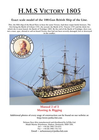
  • 1. H.M.S VICTORY 1805 Exact scale model of the 100-Gun British Ship of the Line. This, the fifth ship of the Royal Navy to bear the name Victory, had three major battle honours. The first being the Battle of Ushant 1781, the second, the Battle of St. Vincent 1797 and the third, for which she is most famed, the Battle of Trafalgar 1805. By the end of the Battle of Trafalgar, there was not a mast, spar, shroud or sail on board Victory that had not been severely damaged, lost or destroyed in the conflict. Manual 2 of 3 Masting & Rigging Additional photos of every stage of construction can be found on our website at: http://www.jotika-ltd.com Nelsons Navy Kits manufactured and distributed by JoTiKa Ltd. Model Marine Warehouse, Hadzor, Droitwich, WR9 7DS. Tel ~ +44 (0) 1905 776 073 Fax ~ +44 (0) 1905 776 712 Email ~ nelsonsnavy@jotika-ltd.com
  • 2. Masts & Bowsprit You may find it easier to avoid turning the round dowel into an oval dowel when tapering by using a David plane, draw knife or similar as follows: 1. Slice the dowel (running with the grain), from a round at the start point of the taper to a square at the end of the taper. 2. Repeat this process so that the dowel runs from round at the start of the taper to an eight sided polygon at the end of the taper. 3. Repeat step two as desired so that the dowel runs from a round at the start of the taper to a 16 or 32 sided polygon at the end, of a diameter marginally more than that required. 4. Using medium sandpaper, followed by fine sandpaper the taper can be gently sanded round along its length. The general construction of the masts are identical, therefore, a detailed construction of the foremast only will be given. Bowsprit Using Plan Sheet 7 for reference, construct the bowsprit to the dimensions shown. You should note that the bowsprit top and sides of the bowsprit, at the positioning of the bees, should be filed flat to accommodate the bees and sheaves. Using Plan Sheet 11 for reference, fit the bees and sheaves (415, 416, 417 & 418), the spritsail yard saddle (334), the jibboom support (414) and stop cleats constructed from 1.5x1.5mm walnut. The gammoning saddles are constructed from 1.5x1.5mm walnut, glued to the bowsprit and sanded round. Note: the ends of gammoning saddles and the spritsail yard saddle should be vertical when the bowsprit is positioned on the model. The banding is made from 2mm wide strips of cartridge paper and positioned as shown on Plan Sheet 11. The bowsprit cap (69) is made as shown on Plan Sheet 11. Note: it is extremely important that the bowsprit and jibboom holes through the cap are offset to the port as shown, this will allow the flying jibboom to butt up against the cap when the assembly is complete. It is also important that the cap, when fitted, is perpendicular to the keel and the top and bottom are bevelled to follow the angle of the bowsprit. The holes through the cap should also be angled, this can be achieved by drilling small holes and filing them out with needle files. Note: when the bowsprit assembly is complete, the bowsprit and jibboom are in line with each other while the flying jibboom is offset at 45 degrees from them, above and to the starboard. The dolphin striker and jack staff should also be made up and fitted using Plan Sheet 7 & 11 for reference. Note: the flying jibboom has a vertical notch in the end to accommodate the fore topgallant flagstaff stay (page 18). Likewise, the dolphin striker has a notch fore and aft in the end to accommodate the fore topgallant flagstaff stay. The dolphin striker also need three holes drilled fore and aft as shown on Plan Sheet 11, to accommodate the martingales (page 18). The Fore Lower Mast Using Plan Sheet 6 for reference, make up the fore lower mast to the dimensions given as follows: On the top of the fore lower mast, mark out an 8mm square. Follow the lines of the square down the dowel to a distance of 73.1mm. Using a fine razor saw, saw at right angles across the dowel to each pencil mark at the 73.1mm line. Form the square section using a craft knife, plane, saw, file or similar. When completed, mark out the 6mm square on the dowel to a depth of 5mm and repeat the process, making sure that the 6mm square is central to the 8mm square. Offer the cheeks (343) to either side of the mast and mark their positions onto the mast. Using a plane, draw knife or similar, remove the area of the mast on which the cheeks will fit so that the surface of the cheek will sit flush against the mast. Note: the front and back of the mast in this area should remain rounded with a diameter of 12.7mm. Before the cheeks are glued into position, it may be an advantage to fit the bands of 2mm wide cartridge paper, that pass under the cheeks, as shown on Plan Sheet 10. Glue the cheeks to the mast taking care to ensure they are at the same height as each other, remembering that the ‘tops’ will be located directly on top of them. Identify the fore lower mast top platform (345), gunwale (346), crosstrees (137 & 138) and trestletrees (136). Using Plan Sheet 6, ‘Fore mast tops’ for reference, glue the gunwale to the platform and using 1.5x1.5mm walnut for the battens, glue them to the platform, within the gunwale as shown. Glue together the crosstrees and trestletrees as shown. The ‘notch’ in the trestletrees is a locator for the fid of the topmast when fitted and should be toward the front of the assembly. Note: the crosstrees are of different lengths, ensure the front is put to the front and the rear is put to the rear in relation to the fid notch. When complete, glue the crosstree and trestletree assembly to the underside of the top platform. At this stage, put the lower mast and top assembly to one side, do not glue them to one another. ©2003 JoTiKa Ltd. 1
  • 3. The Fore Topmast In a similar manner to the lower mast, mark an octagon on the top of the topmast. Using a pencil, mark down the complete length of the dowel all eight lines parallel to each other. Hold the pencil in a normal manner between thumb and forefinger and using your middle finger as a guide, draw down the mast. This is a simple method which becomes very efficient and accurate with a little practise. With the eight lines drawn down the mast, draw the octagon to the base of the mast also. These lines will enable you to easily carve each of the octagonal areas onto the mast in-line with each other. Using Plan Sheet 6 for reference, make up the topmast to the dimensions given. Note: for the two octagons at the base of the topmast, the lowest (smallest) octagon is offset from centre so that the aft face runs directly into the aft face of the second octagon above, as shown. All other octagons are central to the dowel. Also take care in drilling the locating hole for the fid through the second octagon as shown, as this will be fitted into the notch on the fore top trestletrees and if drilled at the wrong height will make correct alignment of the mast impossible. Beware not to fit the fid at this stage or the topmast will not pass through the cap. All fids are made from 1.5x1.5mm walnut to a length of 5mm longer than the width of their respective mast. The octagon at the top of this mast is tapered from a diameter of 5.5mm to a diameter of 6.5mm along a length of 18mm. The remaining 4mm of the octagon has a constant 6.5mm diameter. The top 37mm of the mast is 4mm square. Two side faces of this square section should be inline with the two flat sides of the centre octagon, where it will fit into the ‘top’, remembering that the lowest octagon is offset to the aft of the mast. The sheave assembly can be made up as shown from 1.5x1.5mm walnut and a length of 1x4mm walnut however, the sheaves should not be attached to the mast until the whole mast assembly, including the tops, has been glued together. This also applies to the 0.5x1.5mm battens. Identify the fore topmast trestletrees (139) and fore topmast crosstrees (210) and assemble the topmast top as shown. The Fore Topgallant Mast Using Plan Sheet 6 for reference, make up the topgallant mast to the dimensions given. Mark the octagons and squares onto the mast as described previously, taking care that they are all in-line. Take care also with the positioning of the fid. With all three sections of the foremast constructed, the mast as a whole can be assembled. Starting with the lower mast, identify the bibbs (344). Glue them into position as shown so that the straight back edge and the top edge are flush with the cheeks. With the mast banding fitted, glue the rubbing paunch of 2x4mm walnut to the front of the lower mast as shown 12.7mm off the deck, taking care that it runs vertically and centrally, when in place it should be reduced to 1.5x4mm. Assemble the fore mast boarding pike rack as shown on (Fig 030), and attach it to the mast, the base should be 10mm off the deck and the top should be 25mm above the base. The lower mast banding can now be finished and when completed, the boarding pikes can be glued into the rack. The pikes and pike racks are to be painted black. Identify the foremast cap (66) and fore topmast cap (88). Dry fit the fore top and foremast cap to the lower mast. Do not secure. Now dry fit the topmast, through the cap, insert the fid and position it into its locating notches on the trestletrees. Dry fit the topmast top, topmast cap and topgallant mast in a similar manner. None of the individual components (lower mast, topmast, topgallant mast, caps & tops) should be glued to one another at this stage. With everything dry fitted together, manoeuvre the topmast to run parallel and in-line vertically with the lower mast, at the same time, the lower top should remain parallel to the keel. When you are happy with the alignment, glue the lower mast, lower top, cap, fid & topmast securely. This process should be repeated with the topmast, topmast top, cap, fid and topgallant mast. With the assembly complete, attach the bolsters, of 4x4mm walnut sanded or filed to quarter rounds as shown, to the lower top and the bolsters, of 3x3mm walnut sanded or filed to quarter rounds as shown, to the topmast top. Using lengths of 0.5x3mm walnut cut to 0.5x1.5mm attach the battens to the top square section on the lower mast as shown (ensure the mast banding has been applied first). Also, secure the jeer block strop cleats (144) to the sides. Identify the fore mast hand mast (149) and glue it into position between the crosstree and the underside of the cap. some sanding of the top and bottom will be required to ensure a good fit and the centre section should be filed or sanded round. The topmast sheaves, constructed earlier can now be fitted. Identify the foremast cap saddles (348 & 349) and secure to the cap as shown on Plan Sheet 10 & (Fig 036). Finally locate and fit the mast finishing cap (347). 2 ©2003 JoTiKa Ltd.
  • 4. Fig 030 Mast Colours The masts are painted as follows: The lower mast including banding, cheeks, rubbing paunch etc. is painted yellow up to the bibbs, from the bibbs to the lower mast cap is painted black. The whole of the lower top is also painted black. The hand mast is painted yellow. The topmast is painted black from the base to the lower mast cap. From the lower mast cap to the topmast top is left natural (stained walnut). From the topmast top to the cap is painted black. The whole of the topmast top is painted black. The topgallant mast is painted black from the base to the topmast cap. From the topmast cap to the start of the octagonal of the hounds is left natural (stained walnut). From the start of the octagonal of the hounds to the end of the square of the hounds is painted black. From the top of the square of the hounds to the top is left natural (stained walnut). This is all visible on the box art. The Main Mast Using Plan Sheets 6 & 9 for reference, the main mast is constructed in the same manner as the fore mast with the following points of note: 1. There is a pronounced rake on the main mast as can be seen on the drawings. This angle is pre-determined by the main mast slot in the keel. 2. The cheeks and bibbs both have angled upper edges to match the rake of the mast. This is to allow the lower top to run parallel to the keel when in position, i.e. the top is not at 90 degrees to the mast. Ensure these angled edges are identified and the cheeks and bibbs fitted accordingly. 3. This same angle should be introduced to the topmast top when it is fitted so that it too runs parallel to the keel. 4. Both the lower mast caps and topmast caps are at 90 degrees to the mast, i.e. they are not parallel to the keel. 5. Remember to fit the boarding pike rack into position as described for the fore mast. ©2003 JoTiKa Ltd. 3
  • 5. The Mizzen Mast Using Plan Sheets 6 & 8 for reference, the mizzen mast is constructed in the same manner as the fore mast with the following points of note: 1. There is a pronounced rake on the mizzen mast as can be seen on the drawings. This angle is pre-determined by the mizzen mast slot in the keel. 2. The cheeks bibbs and tops are to be fitted with the same considerations as listed for the main mast. 3. The mizzen lower mast should not be tapered to accommodate the mizzen cheeks, instead the cheeks are fitted directly to the mizzen mast. 4. There is no rubbing paunch on the mizzen mast. 5. There is no mizzen topgallant mast fid. The topgallant mast sits directly into the tops without the need for a fid. 6. The tolerances, particularly for the topgallant mast are critical. As a result, the topmast cap has had to be produced in two halves. The build process for the mizzen mast remains the same as the other masts except for this. 7. Referring to Plan Sheet 6 you should notice on the topgallant mast that the octagonal pattern is tapered along its entire length. In other words, it is tapered from 2.5mm to 4mm along the entire 7mm length and there is no straight octagonal on the top. 8. Do not forget to fit the mizzen mast circular fife rail (207), it is positioned 13mm off the deck, there is no boarding pike rack for the mizzen mast. Yards & Booms Using Plan Sheet 7 for reference, make up the yards and booms to the dimensions shown. The centre, octagonal sections, of the fore and main yards are constructed by securing 8 lengths of 0.5x4mm walnut to the dowel. Note: the batten on the aft face is twice the length of the other seven. For the fore yard it measures 188mm compared to 94mm for the other seven. For the main yard it measures 216mm compared to 108mm for the other seven. The centre, octagonal sections, of the fore and main topmast yards are constructed by securing 4 lengths of 0.5x3mm walnut to the dowel, with spacers also of 0.5x3mm walnut as shown. The centre of the mizzen crossjack yard has a length of 05x1mm walnut (cut from 0.5x3mm) secured to its aft face. Also, the mizzen topmast yard has four lengths of 0.5x2mm walnut (cut from 0.5x4mm) secured to the top, bottom, fore and aft faces. The stop cleats on all yards are constructed from 1.5x1.5mm walnut shaped as required. Note: the stop cleats on the aft only of the topmast yards double as snatch blocks for the topgallant yard sheets. To simulate this, cut a piece of 1.5x1.5mm walnut (or scrap 1.5mm ply) to length and, using a needle file, file a semi-circular notch out of one face. This face is then glued against the yard as shown (Fig 031). Fig 031 Cut cleat from 1.5mm walnut, file a notch in one face, glue to aft face only of topmast yards. Note: all booms are secured to the yards through yard rings as shown and are offset through 45 degrees above and fore of the yard. The outermost rings are located, using brass wire, to holes drilled into the end of their respective yards, through the brass etched boom iron straps where appropriate. Mast & Yard Blocks With the masts and yards assembled and referring to Plan Sheets 8, 9, 10 & 11 & (Fig 33 - 44) fit the blocks, eyelets, horses and flemish horses to the masts, yards and tops as shown. Unless directed otherwise on the plan, the smaller blocks (2 - 5mm) should be attached with 0.25mm black thread and larger blocks (7mm +) should be attached with 0.5mm black thread. Note: all of the blocks on the yards should be positioned directly on top of or directly underneath the yards, i.e. they are all ‘behind’ the booms. Note: when instructed to use the pre-cut blocks (10mm & 7mm open heart blocks, 10mm triple & double jeer blocks and the 8.5mm triple cat blocks), you will need to file a slight groove around the outer edge to take the strop as shown (Photo 041). 4 ©2003 JoTiKa Ltd.
  • 6. Photo 041 Shipping the Masts Using Plan Sheets 8, 9, 10 & 11 for reference, temporarily drill and pin the yards in place on the masts and bowsprit. With the locations marked, drilled and pinned, remove the yards and set them to one side, they will not be finally fitted until needed for the running rigging. Identify the mizzenmast poop sleeve (153), main mast quarterdeck sleeve (156) and fore mast quarterdeck sleeves (376 & 377). Construct the sleeves as shown (Fig 032). Pass the masts through their respective sleeves and step the masts into their locating holes on the deck, adjust the masts to the desired rakes and secure the sleeve to the deck (ensure the masts are all aligned when viewed fore and aft). Secure the masts in place. With the masts in place, a pair of small cleats (662) are secured to the base of both the main and fore lower masts, just forward of the centreline and between the mast sleeve and pike rack base, as shown (Fig 030). ‘Top’ Rails & Lantern Identify and paint black the rail stanchions for the tops (514). The stanchions are fitted to the top of the gunwale, equally spaced along the aft edge. There are five stanchions fitted across the back of the fore top, five across the main top and four across the mizzen top. Cut to length and paint black lengths of 1.5x1.5mm walnut to fit into the ‘U’s’ of the rail stanchions across the tops. Identify, paint and assemble the small Admiral’s lantern components (540, 658 & 659). The lantern can be assembled in the same manner as the transom lanterns. The lantern is fitted, on brass wire, into the centre of the aft face of the main top. Fig 032 ©2003 JoTiKa Ltd. 5
  • 7. Fore Lower Top Blocks Fig 033 Fore Lower Top (‘Top’) Fig 034 Fore Lower Top (Underside) 6 ©2003 JoTiKa Ltd.
  • 8. Fore Topmast Top Blocks Fig 035 Fore Topmast Top Fore Lower Mast Cap Blocks Fig 036 Fore Lower Mast Cap ©2003 JoTiKa Ltd. 7
  • 9. Main Lower Top Blocks Fig 037 Main Lower Top (‘Top’) Fig 038 Main Lower Top (Underside) 8 ©2003 JoTiKa Ltd.
  • 10. Main Topmast Top Blocks Fig 039 Main Topmast Top Main Lower Mast Cap Blocks Fig 040 Main Lower Mast Cap ©2003 JoTiKa Ltd. 9
  • 11. Mizzen Lower Top Blocks Fig 041 Mizzen Lower Top (‘Top’) Fig 042 Mizzen Lower Top (Underside) 10 ©2003 JoTiKa Ltd.
  • 12. Mizzen Topmast Top Blocks Fig 043 Mizzen Topmast Top Mizzen Lower Mast Cap Blocks Fig 044 Mizzen Lower Mast Cap ©2003 JoTiKa Ltd. 11
  • 13. Standing Rigging Note: all b numbers in these rigging instructions refer to belaying points as described. All of these points can be found on Plan Sheet 18, unless otherwise stated. The rigging plans have been drawn following extensive research, contemporary and modern. We would recommend that you follow these drawings exactly unless you are converting the model to an earlier or later version of the ship. Note: never use super glue on the rigging unless specifically stated in the instructions. Brushed on watered down PVA should be used for the majority of the knots. Super glue can be applied to the end of the rigging to aid threading through the blocks. Where a copper eyelet (with rigging passing through it) is secured directly to a mast, a turn of 0.25mm black thread should be lashed around the mast, once close below the eyelet and once close above the eyelet. This is to simulate a thimble as shown (Fig 045). Fig 045 Insert eyelet. Rig one turn of thread below. Rig one turn of thread above. Tackle Pendants: Starting with the tackle pendants, for the lower masts there are two pairs on the fore and main mast, and one pair on the mizzenmast (called the burton pendants). The main and fore mast are of 1.3mm black thread, seize a small loop in both ends and run one end through the lower mast top (starboard for the first pair), around the main mast until the pair are at equal lengths running abreast of the masts. They should be level with the futtock stays and catharpins as shown on the rigging plans. Tie the two halves together with 0.25mm black rigging thread and push the knots to the top of the mast near the bolsters. The mizzen burton pendant is made in a similar manner from 0.5mm black thread. For the topmasts, there is one pair on each side of the fore and main and none on the mizzen. These are again constructed in the same manner as the lower mast pendants from 0.75mm black thread. 12 ©2003 JoTiKa Ltd.
  • 14. Lower Mast Shrouds: Shrouds are next to be set-up and a formal sequence must be adhered to. Forward starboard, forward port alternating. The fore and main mast shrouds are from 1.3mm black thread and the mizzen are from 0.75 black thread, as shown on Plan Sheet 12 together with the appropriate deadeye sizes (The deadeyes are attached to the channels as shown on Plan Sheet 2). Roughly measure out the length of each pair of shrouds and cut the required number of pairs before setting up (they get longer as you progress). Rig one end of each shroud with the appropriate size deadeye. The upper and lower deadeyes need to be correctly and uniformly spaced. The spacing for the lower mast deadeyes should be 20mm . A small jig can be made as follows, cut two lengths of 1mm wire approximately 40mm long, bend 10mm from each end to an angle of 90 degrees. This should leave 20mm between each end. A similar jig can be made (in different size material) for different size blocks. The spacing for the fore and main topmast deadeyes should be 15mm and the mizzen 13mm. One end of the jig can be slotted into the middle hole of the lower deadeye with the other end into the middle hole of the shroud deadeye. Thread the loose end of the shroud through the ‘top’ around the mast, back through the ‘top’ and down to the second deadeye. Insert a loose deadeye into the second spacing jig with the other end of the jig in the corresponding deadeye. The loose end of the shroud should then be wrapped around the deadeye with 0.25mm black thread. Tie the pair of shrouds together near the tops and then push the knot up to the bolster. Rig the lanyards (cable laid) to the deadeyes using 0.5mm natural thread as shown on Plan Sheet 12, ‘Rigging detail’. Continue this procedure until all the lower mast shrouds have been set up. There is a futtock stave to each set of shrouds (both lower and topmast shrouds). These are cut from 1mm brass to the length of the spread of the shrouds at the position to which they are to be tied using 0.25mm black thread, as shown on Plan Sheet 12. Tie each shroud to the futtock stave with a simple clove hitch. Note: the futtock stave is positioned across the shrouds at a distance as far below the ‘top’ as the mast cap is above the ‘top’ as shown on Plan Sheet 12, ‘Shroud, futtock stave & catharpin assembly’. Each port futtock stave is tied to the opposite starboard futtock stave by ropes called catharpins as follows: There are six catharpins on the fore and main lower mast made from 0.75mm black thread, they are tied in position between shrouds 4 through 9. The mizzen lower mast has two catharpins of 0.5mm black thread tied between shrouds 5 and 6. The topmast futtock staves will be dealt with at a later stage. Futtock Shrouds: Identify the deadeye and futtock strop sizes from the plan. Insert the deadeye into the strop and position the strop into the slots as shown on Plan Sheet 12, ‘Fitting of deadeye futtock strops’. The futtock strops are attached to the futtock staves by the futtock shrouds and small brass etched rigging hooks (547), as shown. The futtock shrouds are 0.75mm black thread for the fore and main masts and 0.5mm black thread for the mizzen. Topmast Shrouds: The topmast shrouds are set up in a similar manner to the lower mast shrouds using the appropriate size material as shown on Plan Sheet 12. There is a pair of 0.7mm brass futtock staves on the topmast shrouds as already described above, there are no catharpins. Note: two 3mm single blocks (one per side) should be secured between the first and second topmast shrouds as close under the ‘top’ as possible, on all masts and are used for the topmast yard lifts when rigged. Topgallant Shrouds: The topgallant shrouds are secured to the top of the mast as shown on Plan Sheet 12 and lead through the holes in the end of the topmast top crosstrees and are tied off to the topmast futtock staves. There are three pairs for the fore and main mast of 0.5mm black thread and two pairs of 0.25mm black thread for the mizzen. Note: two 3mm single blocks (one per side) should be secured between the first and second shrouds as close under the ‘top’ as possible, on all masts and are used for the topgallant mast yard lifts when rigged. These blocks are shown on Plan Sheet 8, 9 & 10 as blocks secured in a strop around the topgallant shrouds. As the topgallant shrouds are close together, at this scale, you may find it of benefit to rig these blocks in a strop as shown and run the first and second shrouds as falls from the arse of the blocks. Ratlines: This stage will require a considerable amount of time and patience but the end result will be its own reward. 0.1mm natural thread is used and is secured to each shroud with a clove hitch as shown on Plan Sheet 12, ‘Rigging detail’. They should be uniformly spaced approximately 4.5mm apart. Leave about 15mm of excess thread at each end of each row of ratlines, this will make the process of trimming the ends much easier. For the lower masts only, the foremost and aftermost shrouds are omitted for the first six ratlines above the deadeyes and below the futtock staves. You may also find it beneficial not to apply the two or three lower ratlines until after the shroud cleats have been fitted. Identify the locations of the shroud cleats from Plan Sheet 18 and secure them into position (inboard) with 0.1mm natural thread . The cleats and 0.1mm thread should be painted black when in position. Finish the ratlines, brush on watered down PVA and finally trim the ratlines only when dry. Note: the ratlines on Victory are not black. ©2003 JoTiKa Ltd. 13
  • 15. Bowsprit: The bowsprit can now be glued into position, ensuring that the cap remains vertical both from the front and side views. The bowsprit is also held in position by two sets of gammoning each of 9 turns in 1mm black thread. The gammoning passes over the bowsprit between the saddles, down past the headrails and through the gammoning slots in the stem. Tie off the gammoning and using 0.5mm black thread lash the nine turns together around the centre within the headrails again with nine turns. Driver Boom and Driver Gaff: It would be normal practice to attach these now, however in order to keep the model to a more manageable size it will be beneficial to ship them at a later stage as described. If you prefer to ship them now, all required instruction can be found on page 26. The Mizzen Stay: The mizzen stay is 1mm black thread and requires an eye and mouse as follows 1. Seize a loop at the end of the stay large enough for the stay to run through it. This loop is called an eye. 2. Thread the eye end of the stay under the ‘top’ around the mast and back down through the ‘top’. 3. Lead the running end of the stay through the eye. 4. Mark a position on the stay where the eye is approximately 50mm below the ‘top’. And remove the stay from the mast. 5. Using 0.5mm black thread, wrap the thread around the position marked on the stay and create a bump large enough to simulate a mouse and prevent the eye from passing over it. 6. Feed the eye end back under the ‘top’ from the port side, around the mast and back down through the ‘top’ on the starboard side. 7. Lead the running end of the stay back through the eye until the mouse holds the eye. The running end now leads through the copper eyelet as shown on Plan Sheet 13 and is tied off to the copper eyelet on the deck, port side of the main mast (b1). The Mizzen Topmast Stay: The mizzen topmast stay is 0.5mm black thread and requires an eye and mouse approximately 28mm below the topmast top. The running end now leads through the copper eyelet on the main mast just below the catharpins. It is then secured to the copper eyelet on the deck, starboard side of the main mast (b2). The Mizzen Topgallant Stay: The mizzen topgallant stay is 0.25mm black thread. The standing end is made fast at the mizzen mast hounds as shown on Plan Sheet 13. It then leads through the hole at the rear of the mainmast cap (Fig 040) and secures to a copper eyelet in the main top, port side (b3). The Main Stay: The main mast stay is 1.8mm black thread and requires an eye and mouse approximately 70mm below the top. Into the running end seize a 10mm closed heart block so that its centre point lies approximately 15mm in front of the fore mast, note, the stay passes on the starboard side of the fore mast. The main stay collar of 1.8mm black thread passes through the aftermost holes in the marines’ walk, between the knighthead and bowsprit and through the hole in the stem, back up through the marines’ walk and is lashed to the starting end. The collar should be of a length that it terminates approximately 25mm in front of the main stay. The collar can be moved round until the lashed ends are hidden at the stem and a 10mm open heart block seized in the uppermost part with 0.5mm black thread. The main stay closed heart block is now lashed to the main stay collar open heart block with 0.75mm natural thread. This is illustrated on Plan Sheet 13, ‘Method of seizing open heart ‘collar’ to closed heart of ‘stays’’. The Main Preventer Stay: The main preventer stay and collar are 1.3mm black thread and the preventer stay requires an eye and mouse approximately 80mm below the top. The main preventer stay and collar are made up in the same way as the main stay and collar but with the following alterations: 1. The open and closed heart blocks are 7mm. 2. The closed heart block in the preventer stay lies approximately 25mm in front of the fore mast, also to the starboard side. 3. The preventer stay collar passes through the foremost hole in the marines’ walk and around the bowsprit. 4. The main preventer stay closed heart block is lashed to the main preventer stay collar open heart block with 0.5mm natural thread. 14 ©2003 JoTiKa Ltd.
  • 16. Snaking: The snaking is 0.1mm natural thread and alternates from the main stay to the main preventer stay and back for the full length between the eye and mouse and closed heart blocks, forming a zigzag pattern. It is advisable to use either an over hand or marling hitch knot at each point. The Main Stay Tackle Pendant: Referring to Plan Sheet 13 for position, the main stay tackle pendant is of 0.5mm black thread with falls of 0.25mm natural thread. The tackle is made up of a 7mm double block seized into the end of the pendant, and a 7mm single block together with a rigging hook (548). At this stage, loosely belay the falls to the fifth skid beam, it can be finally secured after the boat positioning has been determined at the end of the rigging process. The Main Stay Fore Stay Tackle Pendant: The main stay fore stay tackle pendant is made up as per the main stay tackle pendant, again refer to Plan Sheet 13 for position. At this stage, loosely belay the falls to the second skid beam, it can be finally secured after the boat positioning has been determined at the end of the rigging process. The Main Topmast Preventer Stay: The main topmast preventer stay is 0.75mm black thread and requires an eye and mouse approximately 50mm below the topmast top. The running end then passes through a copper eyelet below the catharpins (close to the bibbs) on the foremast and travels down to the deck. At a point approximately 25mm above the deck, seize a small loop in the end of the stay. It is then secured by a 0.5mm natural lanyard of several turns to a copper eyelet on the port side of the fore mast (b4). The Main Topmast Stay: The main topmast stay is 1mm black thread and requires an eye and mouse approximately 45mm below the topmast top. The running end then passes through the 7mm single block lashed to the fore lower mast between the ‘top’ and the cap. It is then secured by lanyard of several turns to a copper eyelet on the starboard side of the fore mast (b5) in the same manner as the main topmast preventer stay. The Main Topgallant Mast Stay: The main topgallant mast stay is 0.5mm black thread. The standing end is tied off at the main mast hounds as shown on Plan Sheet 13. The running end passes through a 3mm single block below the fore topmast cap then down to a span around the fore top trestletrees as shown on Plan Sheet 13 & Plan Sheet 18 ‘Fore top’. A loop is formed in the span and the stay and they are secured together using a 0.25mm black thread lanyard of several turns (b6). The Main Topgallant Flagstaff Stay: The main topgallant flagstaff stay will not be rigged until after the fore topmast preventer stay. The Fore Mast Stay: The fore mast stay is 1.8mm black thread and requires an eye and mouse approximately 55mm below the top. The running end has a 10mm closed heart block seized in it approximately 45mm from the bowsprit. A collar is made up in the same manner as the main stay collar from 1.8mm black thread again with a 10mm open heart block seized in the uppermost part 25mm from the closed heart block. These two blocks are then lashed together with 0.75mm natural thread. The Fore Mast Preventer Stay: The fore mast preventer stay and collar are 1.3mm black thread and the preventer stay requires an eye and mouse approximately 60mm below the top. The fore mast preventer stay and collar are made up in the same way as the fore mast stay and collar but with the following alterations: 1. The open and closed heart blocks are 7mm. 2. The main preventer stay closed heart block is lashed to the main preventer stay collar open heart block with 0.5mm natural thread. Snaking: The snaking is 0.1mm natural thread and alternates from the fore mast stay to the fore mast preventer stay and back for the full length between the eye and mouse and closed heart blocks, forming a zigzag pattern. It is advisable to use either an over hand or marling hitch knot at each point. ©2003 JoTiKa Ltd. 15
  • 17. The Fore Topmast Preventer Stay: The fore topmast preventer stay is 0.75mm black thread and requires an eye and mouse approximately 40mm below the topmast top. The running end passes through the sheave in the port bee of the bowsprit and runs down the port side of the bowsprit with a 7mm double jeer block seized into the end of the stay approximately 35mm from the knighthead. At the same time a 0.5mm natural falls must be seized into the arse of the 7mm double jeer block. A brass rigging hook is now seized into the arse of a 3mm double block which in turn is hooked through a copper eyelet in the forward side of the knighthead. The 0.5mm natural falls are made up into a tackle between the 7mm double jeer and 3mm double block and is belayed to the knighthead below the eyelet (b8). The Fore Topmast Stay: The fore topmast stay is 1mm black thread and requires an eye and mouse approximately 45mm below the topmast top. The running end passes down through the sheave in the starboard bee of the bowsprit and runs down the starboard side of the bowsprit. A block and tackle is made up, to the starboard knighthead, in a similar manner as the fore topmast preventer stay but 10mm double and 5mm double blocks are used in place of the 7mm and 3mm blocks respectfully. The falls belay to the starboard knighthead below the eyelet (b7) The Main Topgallant Flagstaff Stay: The main topgallant flagstaff stay is of 0.25mm black thread. The standing end is made fast at the main topgallant mast cap. The running end passes through an eyelet above the hounds on the fore topgallant mast and then travels down and is secured by a lanyard to a copper eyelet positioned directly above the foremast preventer stay (b9). The Fore Topgallant Mast Stay: The fore topgallant mast stay is of 0.5mm black thread. The standing end is made fast at the fore mast hounds as shown on Plan Sheet 13. The running end passes down and through the copper eyelet behind the collar casting in the top of the jibboom and runs down the port side of the bowsprit. Seize a 3mm double block in the end of the fore topgallant mast stay approximately 30mm from the port knighthead under the marines’ walk. A 3mm single block is lashed to a brass eyelet in the forward side of the knighthead, at the same time a falls of 0.25mm natural thread it tied to the arse of the 3mm single block and forms a tackle between the 3mm single and double blocks and belays to the top of the port knighthead (b10). The Fore Topgallant Flagstaff Stay: The fore topgallant flagstaff stay will be fitted at a later stage after the dolphin striker and martingales have been fitted. The Mizzen Topmast Standing Backstay: The mizzen topmast standing backstay is 0.5mm black thread. Using Plan Sheet 14 for reference the mizzen topmast standing backstay is set up in a similar fashion to the shrouds using two 5mm deadeyes seized onto the mizzen backstay channel as shown. The Mizzen Topmast Shifting Backstay: The mizzen topmast shifting backstay is 0.5mm black thread. Using Plan Sheet 14 for reference, seize a 3mm double block into either end of the stay at a distance from the channel as shown on the drawings. Set up a 3mm single block with a rigging hook (548) seized into the arse together with the tackle falls (in the crown) of 0.25mm natural thread, hook the 3mm single block into the copper eyelet on the mizzen channel and set up the tackle with the 3mm double block. The running end of the tackle is secured around the hook on the 3mm single block. The Mizzen Topgallant Mast Backstay: The mizzen topgallant mast backstay is of 0.25mm black thread. Using Plan Sheet 14 for reference the mizzen topgallant mast backstay is set up in a similar fashion to the shrouds using two 3.5mm deadeyes seized into the mizzen backstay channel as shown. The Main Topmast Breast Backstay: The main topmast breast backstay is of 0.75mm black thread and runs down outside the main lower mast ‘top’. Using Plan Sheet 14 as reference seize a 5mm single block into the lower end of the stay. Through this block reeves a 0.50mm black thread runner, whose after end is made fast to the strop of the third deadeye (from the front) of the main channel. A 5mm single block is turned into the fore end of the runner and a tackle is made up using a 5mm double block seized around the first deadeye strop (from the front) on the channel. The falls are made of 0.25mm natural and are belayed to the breast backstay above the 5mm single block. 16 ©2003 JoTiKa Ltd.
  • 18. The Main Topmast Standing Backstays: There are three pairs of main topmast standing backstays each of 0.75 black thread. The lanyards are of 0.25mm natural. Each pair are set up in a similar manner to the shrouds using a pair of 5mm deadeyes. Using Plan Sheet 14 for reference, the first pair are set up to the foremost deadeye of the main backstay channel, the second pair to the 6th deadeye from the rear of the main channel and the third pair to the 11th deadeye from the rear of the main channel. The Main Topmast Shifting Backstay: The main topmast shifting backstay is of 0.75mm black thread and is made up in the same manner as the mizzen topmast shifting backstay, to an eyelet in the rear of the main channel as shown on Plan Sheet 14. The Main Topgallant Mast Standing Backstay: The main topgallant mast standing backstay is of 0.5mm black thread. It is set up in a similar manner to the shrouds using 3.5mm deadeyes into the aft of the main backstay channel as shown on Plan Sheet 14. The lanyards are of 0.25mm natural thread. The Main Topgallant Mast Royal Backstay: The main topgallant mast royal backstay is of 0.25mm black thread. Each end is secured directly to an eyelet (with a whipping) in the aft of the main backstay channel as shown on Plan Sheet 14. The Fore Topmast Breast Backstay: The fore topmast breast backstay is of 0.75mm black thread, and runs down outside the fore lower mast ‘top’. Using Plan Sheet 14 as reference, seize a 5mm single block into the lower end of the stay. Through this block reeves a 0.50mm black thread runner, whose after end is made fast to the strop of the third deadeye (from the front) of the fore channel. A 5mm single block is turned into the fore end of the runner and a tackle is made up using a 5mm double block seized around the first deadeye strop (from the front) on the channel. The falls are made of 0.25mm natural and are belayed to the breast backstay above the 5mm single block. The Fore Topmast Shifting Backstay The fore topmast shifting backstay is of 0.75mm black thread. Set up in the same manner as the mizzen topmast shifting backstay into a copper eyelet behind the second deadeye from the rear of the fore channel as shown on Plan Sheet 14. The Fore Topmast Standing Backstays: There are three pairs of fore topmast standing backstays each of 0.75mm black thread. They are made up in the same manner as the main topmast standing backstays with 5mm deadeyes. They are set up to each of the three 5mm deadeyes on the fore channel as shown on Plan Sheet 14. The Fore Topgallant Mast Standing Backstay: The fore topgallant mast standing backstay is of 0.5mm black. Set up in the same manner as the main topgallant mast standing backstay with two 3.5mm deadeyes into the aft of the fore channel as shown on Plan Sheet 14. The Fore Topgallant Mast Royal Backstay: The fore topgallant mast royal backstay is of 0.25mm black thread. It is set up in the same manner as the main topgallant mast royal backstay, to an eyelet in the aft of the fore channel as shown on Plan Sheet 14. The Jib Stay: The jib stay is of 0.5mm black thread. The standing end is made fast at the end notch of the jibboom (near the collar casting), it then travels up to the starboard sheave of the fore topmast as shown on Plan Sheet 13. It then passes down to a block and tackle on a copper eyelet on the starboard side of the fore top (Fig 033) (using a 3mm single and 3mm double block), the falls of which are of 0.25mm natural. The running end of the tackle then runs down through the ‘top’ and is belayed to the main top bowline bitts, pin 9, (b11). The Jib Halyard: The jib halyard is of 0.5mm black thread. The standing end is made fast at the end notch of the flying jibboom. It then travels up and through a hole drilled fore to aft in the fore topgallant mast as shown on Plan Sheet 13, then down to a block and tackle on the port side of the fore top as shown (Fig 033). The block and tackle are made up of a 3mm single and 3mm double block into an eyelet with 0.25mm natural falls. The running end of the tackle then runs through the ‘top’ and belays to the main top bowline bitts, pin 4, (b12). ©2003 JoTiKa Ltd. 17
  • 19. The Inner Martingale: The inner martingale is of 0.5mm black thread. Referring to Plan Sheet 14, the standing end is made fast at the collar casting on the jibboom. It then passes through the top hole in the dolphin striker and up through a 3mm single block lashed to the starboard side of the bowsprit behind the bees. It is then belayed to the starboard knighthead (b13). The Outer Martingale: The outer martingale is of 0.5mm black thread. The standing end is made fast as per the inner martingale. It then passes through the second hole in the dolphin striker and up to a 3mm single block lashed to the port side of the bowsprit also behind the bees. It is then belayed to the port knighthead (b14). The Flying Martingale: The flying martingale is of 0.5mm black thread. The standing end is made fast to the notch in the end of the flying jibboom. It then passes through the lower hole in the dolphin striker and also travels through a 3mm single block lashed to the bowsprit behind the bees on the starboard side. It is then belayed to the starboard knighthead (b15). The Fore Topgallant Flagstaff Stay: The fore topgallant flagstaff stay is of 0.25mm black thread. The standing end is made fast at the fore topgallant mast cap. It then travels down through a vertical notch in the end of the flying jibboom, down through the notch in the end of the dolphin striker and up to a 3mm single block lashed to the port side of the bowsprit behind the bees. It is then secured on to the fore stay collar. The Flying Jib Horses: There are two flying jib horses each of 0.5mm black thread and they travel from the end of the flying jibboom to the collar casting on the flying jibboom. The horses are formed from overhand knots approximately 8mm apart. The Jibboom Horses: There are two jibboom horses each of 0.5mm black thread and they travel from the collar casting on the jibboom to the bowsprit cap. Again they are formed from overhand knots approximately 8mm apart. The Man Ropes: There are two man ropes each of 0.5mm black thread. The first runs from a copper eyelet in the top of the port side of the bowsprit cap to a copper eyelet in the front of the port knighthead, just below the ‘notch’. The second is identical but on the starboard side. Each is formed from overhand knots approximately 8mm apart. The Boomkin Stays: The boomkin stays are of 0.5mm black thread, one pair per boomkin. They are looped around the groove in the end of the boomkin and each end passes to its respective copper eyelet in the prow as shown on Plan Sheet 11. The Bowsprit Shrouds: The bowsprit shrouds are of 1mm black thread. There are four shrouds (two either side) made up using 5mm deadeyes and arranged as shown on Plan Sheet 11. The standing end is hooked (548) into the copper eyelets in the hull. The lanyards are of 0.5mm natural thread. The Bobstays: There are three bobstays each of 1mm black thread. They are set up in a similar manner to the shrouds also using 5mm deadeyes. The first two bobstays are tied off through the holes in the stem as shown on Plan Sheet 11. The third bobstay runs down to the stem below the first two where it is secured to a span of 1mm black thread either end of which is hooked to copper eyelets in the hull as shown on Plan Sheet 11. 18 ©2003 JoTiKa Ltd.
  • 20. Running Rigging The yards should now be fitted to the masts as follows. The Fore Yard: The fore yard is held in place by a sling, truss pendants and jeers. The sling is of 1.3mm black thread. Loop the sling over the yard within the sling cleats and as the thread passes through itself tie a knot. Tie a second knot just above the first (to simulate two thimbles and a lanyard) (Fig 046). Pass the two ends of the sling up through the hole in the ‘top’ in front of the hand mast and up around the mast cap, between the aftermost slot formed by the cap saddles and tie together using a whipping. There are two truss pendants of 1mm black thread. Tie a loop in one end of the thread just large enough for the opposite end to pass through it, a dab of super glue can be applied to the loop to create a hard ‘eye’. Rig this end off around the yard against the inner edge of the sling cleats so that the eye is aft of the yard. Repeat for the opposite side. Pass the running end of each pendant through the ‘eye’ of the opposite. They then pass down towards the deck and have a 5mm double block seized in their ends approximately 50mm from the deck, with a 0.25mm natural falls tied into the arse of the block at the same time. A second 5mm double block is to be hooked to a copper eyelet on the deck (position shown on Plan Sheet 18). The two 5mm double blocks are formed into a block and tackle with the falls belaying to a small cleat on the side of the base of the fore mast (b16). Referring to Plan Sheet 10 & 15, rig the mast head lashings of seven turns of 0.5mm black thread through the jeer block strop cleats. Next, the two upper triple jeer blocks are to be tied into a strop of 1mm black thread, the strop passes up through the ‘top’ and is lashed to the mast head lashings so that the jeer block is positioned as close to the underside of the ‘top’ as possible. A pair of 10mm double jeer blocks are now lashed to the yard, either side of the sling. The jeer falls themselves are of 1mm natural and is secured around the yard (between the strop and the sling) with a timber hitch and passes up through the triple jeer block and forms a tackle with the double jeer block. The running end passes behind the yard and through the sheaves in the main top bowline bitts and belayed at that point (b17). Fig 046 The Fore Topmast Yard: The fore topmast yard is held in place by parrells and beads and a tye. 11 parral ribs and 20 parral beads are secured in position with 0.25mm black thread within the sling cleats. For the tye, there are two 7mm single blocks lashed around the mast above the shrouds as shown on Plan Sheet 15. The blocks hang in a strop and fall below the trestletrees. The 7mm double tye block together with a pair of 3mm single buntline blocks are secured to the centre of the yard with 0.5mm black thread. The pair of tyes are of 0.75mm natural. They are secured directly above the strop (holding the 7mm single blocks). The first tye leads down from the port side and into the rearmost sheave of the tye block then up to the starboard 7mm block and then through the truck on the starboard topmast standing backstay as shown on Plan Sheet 15. The starboard tye travels in the same manner as the port tye (through the foremost sheave in the tye block). A 7mm double block is seized into the end of the tyes just below the trucks and a tackle is formed with 7mm single block held on a pendant (approximately 50mm long) seized to a copper eyelet at the rear of the fore channel. The falls are of 0.25mm natural and belay to the aftermost kevel on the forecastle (adjacent to the belfry) (b18). ©2003 JoTiKa Ltd. 19
  • 21. The Fore Topgallant Yard: The fore topgallant yard is held in place by parrells and beads and a tye. Cut 4 parral ribs in half and use 7 halves and 6 parral beads secured in position with 0.25mm black thread within the sling cleats. For the tye of 0.5mm natural thread, the standing end is tied to the centre of the yard. The running end travels up and reeves through a hole drilled (fore to aft) through the hounds and down towards the fore top. A 3mm double block is tied into the end of the tye just below the topmast cap. A 3mm single block is lashed to a copper eyelet on the fore top as shown (Fig 033) and the falls of 0.25mm natural are tied into the arse of the block at the same time. A tackle is then formed between the 3mm double and 3mm single blocks and the falls then pass down through the top and belay to the pin seven of the main top bowline bitts (b19). The Main Yard: The main yard is held in place by a sling, truss pendants and jeers. The sling is of 1.3mm black thread and is set up as per the fore yard. The truss pendants are of 1mm black thread and are also set up as per the fore yard truss pendants with a block and tackle and belay to small cleats either side of the base of the main mast (b20). The Jeers are set up as per the fore yard jeers and pass through the foremost hole in the quarterdeck (either side of the main mast) and belay to the aftermost upper deck bitts (b21). Use a thin piece of wire as a messenger to thread around the bitts and then attach the jeer to the wire and pull through (repeat several times as several turns will be required). When the jeers are in position, make fast and add a spot of super glue to secure. The Main Topmast Yard: The main topmast yard is held in place by parrells and beads and a tye. 11 parral ribs and 20 parral beads are secured in position with 0.25mm black thread within the sling cleats. The tye is made up as per the fore topmast yard tie, passing through a truck on the main topmast standing backstay as shown on Plan Sheet 15. The falls belay to the aftermost kevel on the quarterdeck (just in front of the poop ladder) (b22). The Main Topgallant Yard: The main topgallant yard is held in place by parrals and beads and a tye. Cut 3 parral ribs in half and use the 6 halves and 5 parral beads secured in position with 0.25mm black thread within the sling cleats. For the tye of 0.5mm natural thread, the standing end is tied to the centre of the yard. The running end travels up and reeves through a hole drilled (fore to aft) through the hounds and down towards the main top. A 3mm double block is tied into the end of the tye just below the topmast cap. A 3mm single block is lashed to a copper eyelet on the main top as shown (Fig 037) and the falls of 0.25mm natural are tied into the arse of the block at the same time. A tackle is then formed between the 3mm double and 3mm single blocks and the falls then pass down through the top and belays to the eleventh pin of the fore brace bitts (b23). The Crossjack Yard: The crossjack yard is held in place by a sling and a truss pendant. The sling is rigged as per the fore main yard and is of 0.5mm black thread. There is only one truss pendant, of 0.5mm black thread, for the crossjack which leads from the starboard side round the back of the mizzen mast, through an eye on the port side then down the port side of the mizzen mast towards the deck. A 3mm double block is tied into the end of the truss approximately 100mm from the deck. A 3mm single block is hooked to a copper eyelet on the deck (position shown on Plan Sheet 18), and the falls of 0.25mm natural are tied into the crown of the block at the same time. A tackle is formed between the two blocks and belays to the circular fife rail on the mizzen mast (b24). The Mizzen Topmast Yard: The mizzen topmast yard is held in place by parrals and beads and a tye. 7 parral ribs and 12 parral beads are secured in position with 0.25mm black thread within the sling cleats. The tye is of 0.5mm natural. The standing end is made fast to the mizzen topmast between the topmast cap and the crosstrees, it then travels down to a 5mm single block lashed to the centre of the yard. It then travels back up and through a sheave drilled (fore to aft) in the hounds. Then down through a truck on the starboard aftermost mizzen topmast stay. A 5mm double block is then seized into the end of the tye approximately 25mm below the mizzen top. A 5mm single block is tied into a strop together with the falls of 0.25mm natural in the crown of the block at the same time. The strop should be of a length that the block is positioned just above the poop hammock cranes when the end is tied into a copper eyelet in the after end of the mizzen channel as shown on Plan Sheet 15. A tackle is formed between the two blocks and the falls are belayed to the medium cleat (b25) on the poop deck directly in front of the large main brace cleat. 20 ©2003 JoTiKa Ltd.
  • 22. The Mizzen topgallant yard: The mizzen topgallant yard is held in place by parrals and beads and a tye. Cut 3 parral ribs in half and use 5 of the halves and 4 parral beads secured in position with 0.25mm black thread within the sling cleats. The tye is of 0.25mm natural. The standing end is secured to the centre of the yard and passes up through a sheave drilled (fore to aft) in the hounds. It then travels down and has a 3mm double block tied into the end just above the topmast top. A 3mm single block is tied to a copper eyelet on the mizzen top as shown (Fig 041) with falls of 0.1mm natural tied to the crown of the block at the same time. A tackle is formed between the two blocks and belays to pin four in the mizzen topsail sheet bitts (b26). The Spritsail Yard: The spritsail yard is held in place by a sling and a strop. The yard is positioned directly in front of the foremost bobstay. The sling is of 0.75mm black thread and passes around the centre of the yard, up over the bowsprit against the front of the jibboom saddle. The strop is of 0.75mm black thread. It is made fast to a copper eyelet in the centre of the bottom aft face of the bowsprit cap. The other end is made fast to another copper eyelet in the front of the centre of the spritsail yard. The Spritsail Topsail Yard: The spritsail topsail yard is held in place by parrals and beads and a halyard. Cut 3 parral ribs in half and use the 6 halves and 5 parral beads secured in position with 0.25mm black thread. The halyard is of 0.25mm natural thread. A 3mm single block is held in a strop to the collar casting in the end of the jibboom with the falls tied to the arse of the block at the same time. A second 3mm single block is tied around the centre of the yard. A tackle is formed between the two blocks and is belayed to the centre pin in the fore topsail sheet bitts (b27). The next stage is the lifts, buntlines and leechlines for each yard as follows. The Fore Yard: The fore yard lifts are of 0.5mm natural thread. Two 5mm single blocks are tied in a span round the mast cap in the foremost slot created by the cap saddles as shown (Fig 036), the lift is tied into the arse of these blocks at the same time. It then travels out to the 5mm single lift block on the yard (lashed to the sheet block), back up through the block in the span around the cap. Then down through the ‘top’ and through the sheave drilled (fore to aft) in the foremost kevel on the forecastle and belays there (b28). The fore yard buntlines are of 0.25mm natural. Tie a toggle in the end of the buntlines (Fig 047). The inner buntline passes through the inner 3mm single buntline block on the yard and travels up through the innermost sheave of the middle 3mm double block under the front of the fore top. It then runs along the underside of the top and through the innermost sheave of the middle 3mm double block at the back of the fore top as shown on Plan Sheet 16, ‘Fore top under-hanging block usage’ and down to the 3rd and 6th forecastle breast beam supports (adjacent to the belfry) (b29). The outer buntline follows the same route but through the outer sheave of the same 3mm double blocks and belays at the same point. The leechlines are of 0.25mm natural and are set up in the same manner as the buntlines but pass through the outermost sheave in the outer 3mm double blocks under the top. They then pass down and belay to the 1st and 8th forecastle breast beam supports (b30). ©2003 JoTiKa Ltd. 21
  • 23. Fig 047 The Fore Topmast Yard: The fore topmast yard lifts are of 0.5mm natural thread. The standing end is made fast to the topmast cap and the running end travels down to the 5mm single block at the stop cleat on the yard, back up and through the 3mm single block strapped into the topmast shrouds. It then travels down ‘through’ the fore top and is belayed to the second (from the front) shroud cleat on the fore channel (b31). The buntlines are of 0.25mm natural thread. Two 3mm single blocks are lashed to the middle topmast crosstrees as shown (Fig 035). Again tie a toggle in the end of the buntline. Pass the line through the 3mm single buntline block on the yard and it then travels across and through the 3mm single buntline blocks held in a span to the tye block and up through the 3mm single blocks lashed either side to the centre crosstree. It then leads down outside the ‘top’ and belays to the fourth (from the front) shroud cleat on the fore channel (b32). The Fore Topgallant Yard: The fore topgallant yard lift is of 0.25mm natural thread. The standing end is made fast above the topmast rigging (shrouds, backstays etc.) and leads down to the 5mm single lift block at the stop cleat on the yard, back up through the 3mm single block strapped into the topgallant shrouds. It then passes down and is secured to a futtock strop on the fore top (b33). The Main Yard: The main yard lifts are of 0.5mm natural thread and are rigged as per the fore yard. The falls pass through the sheave drilled (fore to aft) in the foremost kevel on the quarterdeck abreast the main mast and belays there (b34). The buntlines are of 0.25mm natural and are rigged as per the fore yard, passing through the inner double blocks under the main top as shown on Plan Sheet 16, ‘Main top under-hanging block usage’ and they belay to the main top bowline bitts pins five & six (b35). The leechlines are of 0.25mm natural thread and are rigged as per the fore yard, passing through the outer 3mm single blocks under the main top and belay pins four and twelve of the fore brace bitts (b36). The Main Topmast Yard: The main topmast yard lifts are of 0.5mm natural thread and are rigged as per the fore topmast yard. The lift belays to the foremost pin of the fife rail abreast the main mast (b37). The buntlines are of 0.25mm natural thread and are rigged as per the fore topmast yard. They come down outside the tops and belay to the third pin of the fife rail abreast the main mast (b38). 22 ©2003 JoTiKa Ltd.
  • 24. The Main Topgallant Yard: The main topgallant yard lift is of 0.25mm natural thread and is rigged as per the fore topgallant lift. It belays to a futtock strop on the main top (b39). The Crossjack Yard: The crossjack yard lift is of 0.25mm natural thread, rigged as per the fore yard (but substituting 3mm blocks in place of the 5mm blocks). It belays to the mizzen mast circular fife rail (b40). The Mizzen Topmast Yard: The lift is of 0.25mm natural thread rigged as per the fore topmast yard (again substituting 3mm blocks in place of the 5mm blocks). It belays to the first shroud cleat (from the front) of the mizzen channel (b41). The buntlines are of 0.25mm natural thread and are rigged as per the fore topmast yard. they belay to the second shroud cleat (from the front) of the mizzen channel (b42), The Mizzen Topgallant Yard: The lift is of 0.25mm natural thread. The standing end is made fast to the end of the yard, against the outside of the stop cleats. They pass up and through the 3mm single blocks strapped to the topgallant shrouds and lead down into the top and belay around a deadeye strop (b43). The Spritsail Yard: The standing lift is of 0.5mm black thread. One end is tied around the yard approximately 70mm from the centreline of the yard and the opposite end is tied to a copper eyelet directly under the aft edge of the bees. The lift is of 0.5mm natural thread. A pair of 5mm single blocks are seized in a span around the bowsprit cap, between the bowsprit and jibboom. The standing end of the lift is seized to a copper eyelet on the side of the bowsprit cap. It then runs through the 5mm single lift block in the end of the yard and back through the 5mm single block in the span around the cap and leads down to the forecastle, belaying to the second and seventh timberheads on the beakhead (b44). The buntlines are of 0.25mm natural thread. A toggle is tied in one end. It then passes through the 3mm single buntline block on the yard, it then leads up to and through copper eyelets on the bowsprit (under the eyelets for the standing lift). They then lead in to the forecastle, belaying to the fourth and fifth timberheads on the beakhead (b45). The Spritsail Topsail Yard: The lift is of 0.25mm natural thread. The standing end is made fast to the end of the yard (against the outer edge of the stop cleats). It leads up to two copper eyelets, one each side of the jibboom collar casting and down to the forecastle where they belay to the first and eighth timberheads on the beakhead (b46). The next stage is the cluelines and sheets as follows. You should note that the lower yard cluelines and sheets run between the lower yards and the hull, the topmast yard cluelines and sheets run between the topmast yards and lower yards and the topgallant yard cluelines and sheets run between the topgallant yards and topmast yards. This is worth bearing in mind and may appear to be obvious but this stage of the rigging can become confusing. The fore and main lower yard cluelines and sheets will not be rigged until the end (along with the tacks) to allow easier access for the rest of the rigging. Refer to Plan Sheet 16 for the clueline standing end positioning of each yard. The Spritsail Yard: The spritsail yard sheet is of 0.5mm natural thread. The standing end is seized to a copper eyelet in the ships’ side as shown on Plan Sheet 16 and travels towards the 3mm single clue block. A 3mm single block is seized into the end of the sheet approximately 25mm from the spritsail yard. The clueline is of 0.25mm natural thread and the standing end is tied to the spritsail yard as shown on Plan Sheet 16. It reeves through the 3mm single sheet block, then up through the 3mm single clueline block and belays to the third and sixth timberheads on the beakhead (b47). The Spritsail Topsail Yard: The spritsail topsail yard sheet is of 0.5mm natural thread. The standing end is made fast to the end of the spritsail yard (outside the lift etc.) and leads up towards the 3mm single clueline block on the spritsail topsail yard. A 3mm single block is seized in the end of the sheet approximately 30mm from the spritsail topsail yard. The clueline is of 0.25mm natural thread and the standing end is made fast to the spritsail topsail yard as shown on Plan Sheet 16. It reeves through the 3mm sheet block, back up through the 3mm clueline block and belays to the beakhead fife rail (b48). ©2003 JoTiKa Ltd. 23
  • 25. The Fore Topmast Yard: The fore topmast yard sheet is of 1mm natural thread. The easiest method of rigging the sheet is to work backwards, that is to say you will start at the belayed end and work to the sheet block. The sheet is belayed to the outer parts of the fore topsail sheet bitts (b49). The sheet is then led through the inner 7mm shoulder block (on the fore lower mast yard), along the yard and through the 7mm sheet block on the end of the lower yard. It then leads up towards the 5mm single clueline block on the topmast yard. A 5mm single block is seized in the end of the sheet approximately 25mm from the clueline block. The clueline is of 0.5mm natural thread. The standing end is made fast to the topmast yard as shown on Plan Sheet 16. It then reeves through the 5mm single block in the end of the sheet, back up through the 5mm single clueline block, through the 5mm single block seized into a copper eyelet on the aft underside of the lower mast cap and leads down through the lower ‘top’ and belays to the 3rd (from the front) lower shroud cleat on the fore channel (b50). The Fore Topgallant Yard: The fore topgallant yard sheet is of 0.25mm natural thread. Again it is worked backwards. The sheet is belayed to the 6th (from the front) lower shroud cleat on the fore channel (b51). It passes up (through the lower ‘top’) to the 3mm single shoulder block on the topmast yard, along and through the snatch block on the aft of the topmast yard and then leads up towards the 3mm clueline block on the topgallant yard. A 3mm single block is seized in the end of the sheet approximately 30mm from the clueline block. The clueline is of 0.25mm natural thread. The standing end is made fast to the topgallant yard as shown on Plan Sheet 16. It then reeves through the 3mm single block in the end of the sheet, back up through the 3mm single clueline block on the yard, down and through the 3mm single clueline block on the aft of the topmast top (see page 7) and leads down outside the lower ‘top’ and belays to the 7th (from the front) lower shroud cleat on the fore channel (b52). The Main Topmast Yard: The main topmast yard sheet is of 1mm natural thread. The sheet is belayed to the aftermost upper deck bitts (b53) (as per the main yard jeers). It passes up through the foremost opening in the quarterdeck (abreast the main mast) and is then rigged as per the fore topmast yard sheets. The clueline is of 0.5mm natural thread. The standing end is made fast to the topmast yard as shown on Plan Sheet 16 and is rigged as per the fore topmast cluelines. It belays to the second pin of the small fife rail abreast the main mast (b54). The Main Topgallant Yard: The main topgallant yard sheet is of 0.25mm natural thread. It is rigged as per the fore topgallant yard with the sheet belayed to the first pin of the large fife rail on the quarterdeck (b55). The clueline is of 0.25mm natural thread. The standing end is made fast to the topgallant yard as shown on Plan Sheet 16. It is then rigged as per the fore topgallant yard and belays to the second pin on the large fife rail on the quarterdeck (b56). The Mizzen Topmast Yard: The mizzen topmast yard sheet is of 0.5mm natural thread. It is rigged as per the fore topmast yard sheet (substituting the 7mm blocks with 5mm blocks), the running end passes through the sheave in the mizzen topsail sheet bitts and belays there (b57). The clueline is of 0.25mm natural thread. The standing end is made fast to the topmast yard as shown on Plan Sheet 16. It then reeves through the 5mm single block in the end of the sheet, back up through the 5mm single clueline block, it then leads down outside the lower ‘top’ and belays to the 3rd (from the front) lower shroud cleat on the mizzen channel (b58). The Mizzen Topgallant Yard: The mizzen topgallant yard sheet is of 0.25mm natural thread. It is rigged as per the fore topgallant yard (substituting the 5mm blocks with 3mm blocks) and belays to the second and fifth pins of the mizzen topsail sheet bitts (b59). The clueline is of 0.1mm natural thread. The standing end is made fast to the topgallant yard as shown on Plan Sheet 16. It is rigged as per the fore topgallant cluelines and belay to 5th (from the front) lower shroud cleat on the mizzen channel (b60). The next stage is the braces, attach all brace blocks as shown on Plan Sheet 8, 9 & 10 (all, except the mizzen topgallant yard, use pendants), they are then rigged as follows. The Spritsail Yard: The spritsail brace is of 0.25mm natural thread. The brace is made fast around the main fore stay collar, just above the mouse. It then reeves through the 5mm single brace block on the spritsail yard and then up, under the fore top sharing the 3mm double blocks (fore and aft) with the leech line. They then pass down belaying to the 2nd and 7th timberheads abreast the belfry (b61). The Spritsail Topsail Yard. The spritsail topsail brace is of 0.25mm natural thread. The brace is made fast to the end of the spritsail topsail yard and reeves under the fore top, through the 3mm single blocks (fore and aft). They then pass down and belay to the 4th and 5th timberheads abreast the belfry (b62). 24 ©2003 JoTiKa Ltd.
  • 26. The Fore Yard: The fore yard brace is of 0.5mm natural thread. The standing end is made fast to the collar of the main stay (above the mouse). It passes through the 5mm single brace blocks on the fore yard and then travels through the two (one per side) 5mm single blocks tied in a span to the collar of the main stay, above the standing end of the brace. It then leads down to the quarterdeck, through the sheave holes in the fore brace bitts and belay here (b63). The Fore Topmast Yard: The fore topmast yard brace is of 0.5mm natural thread. The standing end is made fast to the collar of the main stay (above the mouse). It then passes through the 3mm single brace blocks on the fore topmast yard and then travels through the two (one per side) 5mm single blocks tied in a span to the collar of the main stay, below the standing end of the brace. It then travels down the main stay to two (one per side) 5mm single blocks tied in a span onto the main stay as shown on Plan Sheet 17. Each brace then travels through two (one per side) single blocks tied into copper eyelets located into the aft edge of the front skid beam surround (each 33mm off centre as per the brass rod passing through the second skid beam). They are positioned between the second and third and the sixth and seventh timberheads abreast the belfry. After passing through these 3mm blocks, the brace belays to pins positioned inline with the 3mm blocks through the second (from the front) skid beam (b64). The Fore Topgallant Yard: The fore topgallant yard brace is of 0.25mm natural thread. The standing end is made fast to the collar of the main topmast stay (above the mouse). It then passes through the 3mm single brace block on the topgallant yard and then travels through the two (one per side) 3mm single blocks tied in a span to the collar of the main topmast stay, below the standing end of the brace. It passes forward to the 3mm single blocks tied into copper eyelets in the back edge of the fore top and pass down and belay to the cleats on the belfry supports (b65). The Main Yard: The main yard brace is of 0.5mm natural thread. The standing end is tied into a copper eyelet on the outer hull just below the poop snatch block as shown on Plan Sheet 17. It then passes through the 5mm single brace block on the main yard and back down to and through the poop snatch block. It belays to the large cleat on the poop deck (b66). A lizard and span of 0.25mm natural thread, as shown on Plan Sheet 17, ‘Lizard & span’, should also be rigged between the brace and the aftermost mizzen shroud. The Main Topmast Yard: The main topmast yard brace is of 0.5mm natural thread. The standing end is made fast to the collar of the mizzen stay (above the mouse). It then passes through the 3mm single brace blocks on the main topmast yard and travels through two (one per side) 3mm single blocks tied in a span around the mizzen mast below the bibbs. The braces then pass through the sheaves in the mizzen topsail bitts and belay there (b67). The Main Topgallant Yard: The main topgallant yard brace is of 0.25mm natural thread. The standing end is made fast to the collar of the mizzen topmast stay (above the mouse). It then passes through the 3mm single brace block on the topgallant yard and then travels back and through two (one per side) 3mm single blocks tied in a span to the collar of the mizzen topmast stay, below the standing part of the brace. It passes down, outside the ‘top’, and belays to the fourth (from the front) lower shroud cleat on the mizzen channel (b68). The Crossjack Yard: The crossjack yard brace is of 0.25mm natural thread. Note: the brace block is tied in a pendant approximately 35mm in from the end of the yard. It should also be noted that the braces will pass forward and cross each other (port brace to starboard shroud and starboard brace to port shroud). The standing part of the starboard brace is made fast to the aftermost port main lower shroud, just below the catharpins. It then leads back and through the starboard 3mm single brace block on the crossjack yard. It then passes back to the aftermost port main shroud and through a 3mm single block tied directly under the standing end. It then leads down and belays to the 6th pin (from the front) on the large fife rail on the quarterdeck (b69). The port brace is rigged in the same manner. The Mizzen Topmast and Topgallant Yards: The mizzen topmast and topgallant yard braces will be rigged with the driver gaff. ©2003 JoTiKa Ltd. 25
  • 27. The driver boom and driver gaff should now be fitted as follows. The Driver Gaff: The driver gaff is held in place by parral beads, a throat halyard and a peak halyard. Use 12 parral beads secured in position with 0.25mm black thread. The throat halyard is of 0.5mm natural thread. Using Plan Sheet 17 & 18 for reference, one 5mm double block is secured to a copper eyelet on the top of the driver gaff throat and a second 5mm double block is secured to a copper eyelet under the mizzen top (starboard side), (Fig 042), and the falls are secured to the arse of this block at the same time. A tackle is set up between these two blocks to hold the gaff at an angle that positions the outer end directly over the transom, the jaws should be bevelled to sit flush against the mast when the gaff is at the correct angle. The running end passes down to a 5mm single block attached to a copper eyelet into the poop deck (starboard side of the mizzen mast, in line with belaying cleat) and belays to the starboard, foremost medium cleat on the poop deck (b70). The peak halyard is of 0.5mm natural thread. The standing end is made fast to the end of the driver gaff as shown on Plan Sheet 17. It then passes through a 5mm double block attached to a copper eyelet in the aft face of the mizzen lower mast cap, it then passes across and through the 5mm single block lashed to the driver gaff as shown. Back through the double block at the cap and down through a 5mm single block attached to a copper eyelet into the poop deck (port side of the mizzen mast) and belays to the port, foremost medium cleat on the poop deck (b71). A pair of 3mm single blocks tied in a span are put over the end of the driver gaff next (for the mizzen topmast yard braces). The mizzen topmast yard braces are now rigged of 0.25mm natural thread. The standing ends can now be made fast to the end of the driver gaff. The running ends then reeves through the 3mm single brace blocks on the mizzen topmast yard and back down, through the two (one per side) 3mm single blocks tied in a span to the end of the driver gaff. They then belay to the outboard cleats of the three cleats on the inboard face of the taffrail (b72). A pair of 3mm single blocks are now tied in a span around the end of the driver gaff (for the mizzen topgallant yard brace) as shown (Fig 048). The mizzen topgallant yard brace is now rigged of 0.1mm natural thread. The standing part is made fast directly on to the yard arm (there are no brace blocks). It passes down through the 3mm single blocks (one per side) tied in a span to the end of the driver gaff and down to the poop deck where it belays to the middle of the three cleats on the inboard face of the taffrail (b73). The vang pendants of 0.5mm black thread are now rigged. Measure the length of thread required (approximately 250mm total). At the centre of the vang, throw a clove hitch over the end of the driver gaff. Tie a 3mm double block into each end (approximately 120mm from the end of the driver gaff). A 3mm single block is attached with a rigging hook to a copper eyelet in the first curve of the taffrail capping as shown on Plan Sheet 18, the falls of 0.25mm natural thread are tied into the crown of this block at the same time. A tackle is set up between these blocks and the running end belays to the inboard of the three cleats on the inboard face of the taffrail (b74). A 3mm single block is now tied to the copper eyelet in the end of the driver gaff for the signal halyard of 0.25mm natural thread. Each end of the halyard belays to the cleat on the inboard face of the taffrail, outside the starboard inner transom knee, above the flag lockers (b75). The Driver Boom: The driver boom is held in place by parral beads and the driver boom saddle. Use 12 parral beads secured in position with 0.25mm black thread. There are a pair of horses on the driver boom which run from the end of the driver boom extending to just in front of the comb cleat on the driver boom. The horses are formed from overhand knots approximately 8mm apart. The guy pendants of 0.25mm black thread go over the end of the driver boom next in a similar manner to the driver gaff vang pendants. Tie a 3mm double block into each end (approximately 75mm from the end of the driver boom). A 3mm single block is attached with a rigging hook to a copper eyelet in the top curve of the taffrail capping (approximately 10mm in from the end) (position shown on Plan Sheet 18), the falls of 0.25mm natural thread are tied into the crown of this block at the same time. A tackle is set up between these blocks and the running ends belay to cleats approximately 5mm in from the eyelets holding the 3mm single blocks on the taffrail (b76). The boom itself should be positioned off centre to the port side to allow the ensign staff to be shipped. The toping lift of 0.5mm natural thread is now put over the end of the driver boom with a clove hitch as per the vang pendants on the driver gaff. They run upwards and forwards to a pair of 5mm single blocks (one per side) in a span under the lower mizzen mast cap. The running end then passes down outside the lower mast ‘top’ (between the second and third topmast shrouds) and a 5mm double block is seized in the ends approximately 40mm below the lower mast ‘top’. A 5mm single block is hooked to a copper eyelet on the mizzen channel (position shown on Plan Sheet 18), the falls of 0.25mm natural thread are tied into the crown of this block at the same time. A tackle is set up between these blocks and the running end belays to the mizzen circular fife rail (b77). The driver boom sheets are rigged as follows. A 3mm double block is tied to the iron horse between the inner transom knees, a second 3mm double block is lashed to the driver boom within the comb cleat, and the falls of 0.25mm natural thread are tied into the arse of this block at the same time. A tackle is set up between these two blocks and the running end belays to the small cleat on the starboard inner transom knee (b78) The ensign staff should now be shipped. 26 ©2003 JoTiKa Ltd.
  • 28. Fig 048 Rigging sequences for the end of the driver boom & gaff ©2003 JoTiKa Ltd. 27
  • 29. The fore and main lower yard cluelines, sheets and tacks are now rigged. It is important that you read the following instructions for the cluelines, sheets and tacks thoroughly before starting as they are joined and all have to be rigged at the same time. The tack, sheet and clue garnet strop assembly should be constructed prior to rigging the clueline, sheet and tack. The method of assembly is shown in (Fig 049). In each case the clue block is a 5mm single and the sheet and tack blocks are 7mm singles. Fig 049 Knot Becket 1. Tie a strop around the block. 2. Using a piece of 2mm dowel or similar, tie a becket into the strop. 3. With the strop and becket complete, harden the Strop becket with a touch of super glue. Repeat steps 1 – 3 until you have eight 7mm single 1 2 3 blocks tied in strops with beckets and four 5mm single blocks tied in strops with beckets. 4. Take two 7mm single blocks and one 5mm single block and align their beckets. 4 5. Tie the beckets together, forming the tack, sheet and clue garnet strop assembly. Repeat steps 4 – 5 until you have four tack, sheet and clue garnet strop assemblies. 5 The Fore Yard: The fore yard clueline is of 0.5mm natural thread. The standing end is made fast to the fore yard to the extreme end of the octagonal on the yard as shown on Plan Sheet 16. It then reeves through the 5mm single clueline block (of the tack, sheet and clue garnet strop assembly) positioned approximately 20mm directly below the standing end, back up through the 5mm single shoulder block and down to the fore topsail sheet bitts where it belays (b79). The fore yard sheet is of 0.75mm natural thread. The standing end is made fast to a copper eyelet on the hull, just in front and below the seventh gunport of the upper gun deck (from the front) as shown on Plan Sheet 16. It travels through the 7mm sheet block (of the tack, sheet and clue garnet strop assembly) and back behind the above-mentioned gunport where it passes through the ships side and belays to the aftermost large cleat on the upper gun deck (b80, Plan Sheet 5). The fore yard tack is of 0.75mm natural thread. The standing end is made fast to the end of the boomkin, it then travels up and through the 7mm single tack block (of the tack, sheet and clue garnet strop assembly). It then passes back down and through a 7mm single block seized to the boomkin outside the standing end, and belays to the top of the headrail (b81). For the benefit of the model, when the clueline, sheet and tack are finally rigged there should be no slack. 28 ©2003 JoTiKa Ltd.
  • 30. The Main Yard: The main yard clueline is of 0.5mm natural thread. The standing end is made fast to the main yard to the extreme end of the octagonal on the yard as shown on Plan Sheet 16. It then reeves through the 5mm single clueline block (of the tack, sheet and clue garnet strop assembly) positioned approximately 25mm directly below the standing end, back up through the 5mm single shoulder block. It then passes down through the foremost opening in the quarterdeck abreast the main mast and belays to the aftermost bitts on the upper gun deck (b82) as per the main yard jeers. The main yard sheet is of 0.75mm natural thread. The standing end is tied to a copper eyelet on the hull, below the spider as shown on Plan Sheet 16. It then leads up and through the 7mm single sheet block (of the tack, sheet and clue garnet strop assembly), back down and through another 7mm single block held in a pendant, of 0.75mm black thread, passing through the spider (the standing end of which is tied to a copper eyelet behind the spider). It then passes up, across and through a sheave hole in the hull as shown on Plan Sheet 16 and belays to the staghorn on the quarterdeck (b83). The main yard tack is of 0.75mm natural thread. The standing end is tied to a copper eyelet in the hull below and behind the fifth (from the front) gunport of the upper gun deck, as shown on Plan Sheet 16. It then passes up and through the 7mm single tack block (of the tack, sheet and clue garnet strop assembly). It then leads back down and passes through the chesstree and through the sheave in the hull (forward of the chesstree) and belays to the foremost large cleat on the upper gun deck (b84, Plan Sheet 5). The Quarter Davits: The quarter davits are constructed as shown (Fig 050). The boat falls are of 0.25mm natural thread. A 5mm single block has the 0.25mm falls at its crown and a hook (548) at its arse. The falls form a tackle with the sheaves in the end of the davits, with the running end belayed to the cleat at the davit base (b85, Fig 050). The 5mm single block can be hooked to a copper eyelet on the underside of the base of the davits for stowage. For ease, this should be done prior to fitting to the hull. The davits are secured to the hull by their brackets (625), either with super glue or by drilling and securing with a dome headed nail. The guys are of 0.5mm black thread. Both ends are seized to copper eyelets, one in the outer side of the davits, the other in the hull as shown on Plan Sheet 17. The jackstay is of 0.5mm black thread. The ends are seized to the copper eyelets on the inner side of the davits. The span of 0.5mm black thread and the lift of 0.75mm natural thread can now be rigged together. The ends of the span are seized to the copper eyelets on the upper face of the davits (not taught, they should be slack to form an inverted ‘V’ when attached to the lift. A thimble is formed in the end of the lift around the centre of the span. The running end travels up and through the 7mm single blocks (one per side) seized in a span under the bibbs of the mizzen mast and belay to the mizzen circular fife rail (b86). Fig 050 ©2003 JoTiKa Ltd. 29
  • 31. The travelling guy, guy pendant and flying jibboom guy should now be rigged as follows. To begin, seize a 3mm single block to a copper eyelet with falls of 0.25mm natural thread tied into the crown of the block at the same time. Repeat this until you have six individual sets. The copper eyelets are then secured into the front face of the beakhead bulkhead plank sheer (380), one directly above each outer edge of the roundhouses and the remaining two above the roundhouse in between them (at the centreline of the roundhouse). The travelling guy is of 0.5mm black thread. This is made from one piece of thread, the centre of the thread is made fast to the jibboom between the bowsprit cap and spritsail topsail yard. Each end then leads out and through the innermost copper eyelet on the top of the spritsail yard out towards the innermost copper eyelets on the beakhead bulkhead plank sheer. 3mm double blocks are seized into the ends approximately 35mm from the plank sheer. A tackle is set up between these blocks and the falls belay to the beakhead bulkhead fiferail (405) above the 3mm single block (b87). The guy pendant is of 0.5mm black thread. This is formed in a similar manner to the travelling guy and the centre of the thread is secured to the necking of the jibboom. It travels back and through the middle copper eyelets on the top of the spritsail and is set up in the same manner as the travelling guy with a tackle to the middle (above the roundhouses) 3mm single block on the plank sheer. The falls are belayed to the beakhead bulkhead fiferail (405) above the 3mm single block (b88). The flying jibboom guy is of 0.25mm black thread. This is formed in a similar manner to the travelling guy and the centre of the thread is secured to the necking of the flying jibboom. It then passes through the outer copper eyelet on the top of the spritsail. It is set up in the same manner as the travelling guy with a tackle to the outer 3mm single block on the plank sheer. The falls are belayed to the beakhead bulkhead fiferail (405) above the 3mm single block (b89). Anchors: The cat falls are of 0.25mm natural thread. The standing end is secured to a copper eyelet on the underside of the cathead directly behind the sheaves. Large rigging hooks are tied into the arse of the 8.5mm triple cat blocks. A tackle is then set up between the 8.5mm triple cat block and the cathead sheaves, the running end belaying around the cathead at the cathead cleat (b90). The anchor ring of 1.5mm brass wire has 0.5mm black thread wound around it to represent puddening. The anchor ring is positioned in the hook of the 8.5mm cat block, and the anchor palm sits against the anchor palm block on the hull. The bower anchor cable of 2.5mm natural rope should be secured to the ring of the anchor with either an inside clinch or with an eye splice. The cable then leads through the innermost hawse hole where it is secured. The anchor should then be secured in a span to the bulwark openings as shown (Photo 042) ensuring the anchor palm rests on the anchor palm block. The sheet anchors are secured in a similar manner as shown, but without a cable. Again ensure the anchor palm rests in the anchor palm block. The kedge anchor is secured to the aft end of the starboard mizzen channel by a strop. Photo 042 Photo 043 Bower Anchor Sheet Anchor 30 ©2003 JoTiKa Ltd.