Qualification of Phillips X’pert MPD Diffractometer for XRD
1. Qualification of Phillips X’pert Diffractometer for
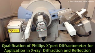
Application in X-ray Diffraction and Reflection
A senior thesis by Jacob Johnson
2. The Instrument
The Phillips X’pert MPD
Diffractometer is a versatile
instrument that is designed
be used in many X-ray data
collection applications.
Interchangeable elements
of the instrument allow for
multiple types of data
collection and sample types
to be accommodated.
3. Qualification of the Instrument for
Applications in X-ray Diffraction and X-ray
Reflection
X-ray Powder Diffraction
The instrument can be configured to
make measurements in X-ray Powder
Diffraction (XRD)
XRD is used to probe the crystalline
structure of solids, the diffraction
pattern can be analyzed to
determine the molecular structure of
a crystal lattice and aids in
crystallography
Qualification of this instrument for
this use is one of the main reasons
that the instrument was acquired
Thin Film X-ray Reflectance
The instrument can be configured to
make measurements in X-ray
Reflectivity (XRR) measurements at a
glancing angle
XRR is used to probe the surface of
thin metallic films to determine their
characteristics
Through another project here at the
university thin metallic films are
being manufactured
Determining the characteristics of
these films is essential for their use
4. Generating X-rays
through characteristic
emission
Characteristic X-ray emission occurs
when a vacancy in an inner bound
state within an atom is filled by an
electron from a more energetic state
in the same atom
When an electron undergoes this
energy transition a photon is emitted,
this emission is called
Under the correct conditions the
photon emitted can have sufficient
energy to be in the X-ray range
5. Hot Cathode X-ray Tube: The X-ray
Source
The hot cathode method of X-ray
generation is used to educe
characteristic X-ray emission
The process uses a hot cathode or
filament to thermally expel electrons
The thermionic electrons are then
accelerated toward a copper anode
target
As the electrons collide with the
copper anode characteristic x-ray
emission is produced as well as
Bremsstrahlung or “white” radiation
The X-rays are then filtered to
suppress the “white” radiation and
all but one characteristic wavelength
By filtering the emitted x-rays a
nearly monochromatic incident beam
is produced
6. X-ray Detector
The detector used for the
instrument is a Xenon gas filled
chamber detector
As X-rays enter the gas filled
chamber the gas’s atoms are
ionized
A sensing wire or plate in the gas
chamber is held at high voltage
accelerating any ionized particles
toward it
As the ionized particles contact the
sensing wire or plate a current is
induced the current is used to
determine the counts of x-rays
entering the detector chamber
7. Calibration
Calibration is essential to
collecting meaningful data
The detector calibration technique
pictured uses a calibration sample
(Fluorite) and compares the
collected powder diffraction data
The average offset over all the
pronounced diffraction peaks is
calculated and the zero offset of
the detector is changed by that
factor
This process can be repeated or
iterated to increase the precision
of the instrument
8. X-ray Beam Path Geometry
For practical constraints and
instrument durability the X-ray
source is held at a fixed position
The incidence of the X-ray beam is
altered by changing the angular
position of the sample (theta)
Since the emission source’s
position is held constant the
detector’s position must proceed
at twice the rate (2 theta) of the
sample’s angular position to collect
x-rays that are
reflected/diffracted specularly
The parameters of a scan can be
altered to collect off-specular
diffuse scattering data
9. Constructive interference and Path
Length Difference
Both XRD and XRR are methods of
determining the conditions for
which the specularly scattered X-
rays achieve constructive
interference
When the path length of waves
emitted from two sources differs
by an integer number of
wavelength the waves will
constructively interfere
𝜑 = 𝑛 ∗ 𝜆 where 𝑛 = 0,1,2,3,4…
10. X-ray Diffraction From a Crystal Lattice
Bragg’s Law governs the conditions
for constructive interference
diffraction based on the angle of
incidence on a crystal lattice
By relating a geometric derivation
of the path length difference of
reflection at subsequent lattice
planes to the conditions for
constructive wave interference the
following equation is derived
𝑛 𝜆 = d sin(𝜃)
Where n = 0,1,2,3… λ is the
wavelength, 𝜃 is the angle of
incidence, and d is the spacing
between the lattice planes
11. Crystallography
Through XRD
The diffraction pattern for a
crystal structure has unique
features that allow it to be
differentiatiated from other
crystal structures
By comparing measured
diffraction data from the
instrument to a database of
know crystal structures the
crystal makeup of the sample
is determined
The data shown to the right is
diffraction data that was
collected by the instrument on
a sample of common rock salt
12. X-ray Reflectance
from Thin Films
As shown in the images at the right the path length
difference in a reflection/refraction boundary is
similar to that of diffraction
The difference is that the transmitted ray is slightly
refracted thus altering the angle of incidence on
any subsequent barriers
The following is an equation similar to Bragg’s Law
with alterations to compensate for refraction:
Since the angles of incidence used for X-rays are
small the equation can be simplified to:
13. Thin Film Characterization
through XRR
The data shown at the right is a
reflectance scan measured with the
instrument of the thin film shown below
The reflection fringes can be clearly
seen as the angle of incidence increases
As the incident angle is changed the
path length difference alternates
between total destructive interference
and constructive interference
This specific thin film is a thin film that
is a single metallic layer, it is possible
that this layer has a thin oxidation layer
on the surface of the film
Through analysis of this reflectance data
the thin film can be characterized
14. Conclusion
The objective of the project was achieved and the instrument
was qualified for the applications of X-ray diffraction and X-ray
reflection
Further research was done to understand the methods of
crystallography from the diffraction data and characterization
of thin metallic thin films from the reflectance data
Written step by step procedures were created for the
operation of the instrument
Tutorial videos were filmed to show the operation techniques
of the instrument as well as sample preparation and sample
stage interchanging to alternate between XRR collection and
XRD
15. Future Work
Multi Layered Thin Film
Manufacturing and Analysis
Single layered films have been
manufactured here through
another student led project
A new electron beam
deposition system may be in
use soon, this system will have
the capability to create
multilayered thin films
Multi Layered thin films can
also be studied through X-ray
Reflectivity
XRD Data Post Processing and
Crystallography of Impure Samples
Many times in nature there are several
types of crystallized material contained
within a bulk sample
The X’per High Score software package
that accompanies the data collection
software of the instrument has the
capability to extract data for
superimposed diffraction patterns from
several crystal types
The data processing and analysis with this
software is something that requires
further attention to be used effectively