
Recomendados
Más contenido relacionado
Similar a CAM-2 NC CNC machines.pdf
Similar a CAM-2 NC CNC machines.pdf (20)
Último
Último (20)
CAM-2 NC CNC machines.pdf
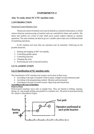
- 1. EXPERIMENT-2 Aim: To study about NC CNC machine tools. 2.1INTRODUCTION Numerical Control Machine Tool: Numerical control of machine tools may be defined as a method of automation, in which various functions and processing of machine tools are controlled by letters and symbols. The letters and symbols are a form of code which gives certain explicit relations to machine operations. The same machine can then be given a variable code to take care of different kinds of machining operations. In NC machine tool more than one operation may be automatic. Following are the possible functions: 1. Starting and stopping of M/C tool spindle; 2. Controlling spindle speed; 3. Controlling feed rate; 4. Changing the tools; 5. Positioning the tools at desired locations. 2.2 CLASSIFICATION 2.2.1 Classification of NC machine tools: The classification of NC machine tool systems can be done in three ways: According to the type of machine: Point-to-point, straight-cut and continuous path According to the programming method: Absolute and incremental According to the type of control system: Open-loop and closed-loop According to the type of machine: Point-to-Point Point-to-point machines move only in straight lines. They are limited to drilling, reaming, boring, etc. and straight milling cuts parallel to a machine axis. The point-to point positioning NC system is illustrated in Figure:
- 2. Straight-cut NC Straight-cut control systems are capable of moving the cutting tool parallel to one of the major axes at a controlled rate suitable for machining. It is, therefore, appropriate for performing milling operation to fabricate work pieces of rectangular configurations. With this type of NC system it is not possible to combine movements in more than a single axis direction. Therefore, angular cuts on the work piece would not be possible. An example of straight-cut operation is shown in Figure: Continuous Path A continuous path machine has the ability to move its drive motors at varying rates of speed while positioning the machine which facilitates cutting of arc segments and angles. The most common type of continuous path operations are milling and lathe operations. In continuous path machine, the tool is cutting while the axes of motion are moving, as for example, in a milling machine. Figure shows continuous path NC system for 2D operations.
- 3. According to the Programming Method: Absolute Programming Absolute positioning is another type of programming system. In this system, the tool locations are always defined in relation to point zero. The position commands are given as absolute distances from the reference point. The reference point can be defined outside the work piece or at a corner of the work piece. The reference point or point zero could be fixed or floating. When the point zero is fixed, the origin is always located at the same position on the machine table. When the point zero is floating, the operation can set the point zero at any position on the machine table. This point zero is decided based on part programming convenience. Incremental Programming Incremental positioning is a programming system used to define the position of the tool in NC machines. In an incremental system, the next tool location must be defined with reference to the previous tool location. The dimensional data applied to the system will be a distance increment measured from the preceding point at which the axis of motion was present. According to the type of Control system: Open Loop Control system: The open-loop NC systems are of digital type and use stepping motors for driving the slides. A stepping motor is a device whose output shaft rotates through by a fixed angle in response to an input pulse. The stepping motors are the simplest way for converting electrical pulses into proportional movement. Closed Loop Control system: The closed-loop control measures the actual position and velocity of the axis and compares them with the help of a comparator. The comparator is a device that compares the output signal with the signal received from the feedback device. 2.3 SPECIFICATION AND COMPONENTS
- 4. Basic components of NC machine are shown in the fig: (1) Programme Instructions (2) Machine Control Unit (MCU) (3) Machine Tools (MT) 2.3.1 Programme Instructions The programme of instructions is the detailed step by step set of directions which tell the machine tool what to do and in what sequence. The part programme is written in coded form and contains all the information needed for machining the component. The part programme is fed to the machine control unit through some input medium. Various types of input media are: (a) Punched cards (b) Magnetic tapes and floppy disks (c) Paper tape Punched cards were once widely used as a medium for data input in all numerical control systems. A typical punched card used in IBM systems has 80 columns and each 'column has numbers which identify the punching position. There are 12 punch positions or rows in each
- 5. card designated as 12, 11 and 0 to 9. For any numeric and alphabet to be punched on the card, a code is used and rectangular blocks are punched on the card at one or more places. Normally, one card is used for encoding each instruction or for storing each master record. Magnetic Tape and Disk Magnetic tapes and disks are widely used for data storage as well as data input to NC systems. The data is stored in the coded form by means of magnetized spots on magnetic medium in both cases. The magnetic tapes and magnetic disks are re-usable media. The data once stored can be erased and new data saved on the magnetic tape or disk. Magnetic tape used in numerical control systems is identical to the tape used in common home tape recorder. The width of the tape is 6 mm or 25 mm. Magnetic disks or floppy disks are circular disks and consist of a material which can be magnetized. The disk is enclosed in a square protective sleeve. The data is stored in concentric tracks arranged on the surface of the disk. The commonly used sizes of magnetic disks are 5.25 inch diameter and 3.5 inch diameter. Punched Tape Punched tape is widely used for feeding the programme to numerical control systems. There are various types of paper tapes used in NC system but the standard format for tape size and configuration, issued by Electronic Industries Association of USA (EIA) and International Standards Organization (ISO), are universally accepted. A standard tape is 25 mm wide. The punched tape has capacity for storing 10 characters per 25 mm length. 2.3.2 Machine Control Unit Every NC machine tool has a main unit, which is known as MCU, consist of some electronic circuitry (Hardware) that reads the NC program, interprets it and conversely translates it for mechanical actions of the machine tool. Housed MCU Swing around MCU
- 6. Stand-alone MCU 2.3.3 Machine Tool The third part of the numerical control system is the machine tool itself. In a numerically controlled machine all the movements of the tool and the machine table are done automatically with the help of electric motors. For example, in case of a CNC lathe the longitudinal and transverse movements of the tool are controlled by two motors fitted on the machine i.e. one for longitudinal movement and the other for transverse movement of the tool. In addition, the speed of the spindle motor is also controlled by the part programme. The machine may have a tool magazine, so that tool changing is done automatically. Also the other functions like machine ON/OFF, coolant ON/OFF, etc are controlled through the part programme. The motors used for controlling the speed, feed and depth of cut are either servomotors or stepper motors which enable the user to select any desired speeds and feeds. 2.4 Construction Details of NC/CNC machine: The basic design of a conventional machine tool is not suitable for CNC machines. In order to take care of above and many other factors, there is a need for special consideration to be given to the design of CNC machine tools in the following areas: (1) Machine structure (2) Slideways (3) Spindle mounting (4) Drive units (5) Elements of transmission and positioning slides (6) Location of transducers (7) Tool and work holding devices (8) Swarf removal (9) Safety (1) MACHINE STRUCTURE The design and construction of CNC machine should be such that it meets the following main objectives: (i) High precision and repeatability (ii) Reliability (iii) Efficiency (2) SLIDEWAYS In the conventional machine tools, there is a direct metal to metal contact between the slideway and the moving slides. Since the slide movements are very slow and machine utilization is also low, this arrangement is adequate for conventional machine tools. The design of slideway in a CNC machine tools should: (a) Reduce friction (b) Reduce Wear (c) Satisfy the requirements of movement of the slides (d) Improve smoothness of the drive (3) SPINDLE At the high cutting speeds and high material removal rates, the spindle carrying the work piece or the tool are subject to deflection and thrust forces. To ensure increased stability and minimize torsional strain, the machine spindle is designed to be short and stiff and the final drive to the spindle is located as near to the front bearing as possible. (4) DRIVE UNITS Drive motors are required to perform the following functions:
- 7. (i) To drive the main spindle (Spindle drive) (ii) To drive the saddles or carriage (Axis drive) In addition there may be some more motors in the CNC machine for services such as coolant pumps, swarf removal, etc. (5) ELEMENTS OF MOTION TRANSMISSION The conventional machines use lead screw for motion transmission purposes. The lead screw with acme-threads is not suitable for CNC machines due to high friction between the lead screw and the nut and poor power transmission efficiency and inaccuracy due to backlash. These problems have been overcome with the use of recirculating ball screw and nut arrangement. The advantages of using ball screw and nut assembly are: (1) High Efficiency (2) Wear and Life (3) Reversibility (4) No Stick-Slip (6) LOCATION OF TRANSDUCERS/CONTROL ELEMENTS In CNC machines the control of all machine functions is totally transferred to a computerized control system. The control unit should be situated so that it is convenient for the operator to operate the machine from the central place. (7) TOOL AND WORK HOLDING DEVICES The cutting time in CNC machine ranges from 70 to 80%, the tooling required for these machine tools needs to be specially designed. The requirements of tool and work holding devices and cutting tools for CNC machines are discussed in the Chapter on "Tooling for CNC Machines". (8) SWARF REMOVAL CNC machines are designed to work at optimum cutting conditions with the improved cutting tools on a continuous operation basis. Since the cutting time is much more in CNC machines, the volume of swarf generated is also more. Unless the swarf is quickly and efficiently removed from the cutting zone, it can affect the cutting process and the quality of the finished product. Also the swarf cannot be allowed to accumulate at the machine tool because it may hamper the access to the machine tool. (9) SAFETY OF OPERATOR
- 8. Safety of operator is very important aspect which cannot be overlooked. To ensure safe working conditions the CNC machine tools are provided with metallic or plastic guards. 2.5 AXIS DESIGNATION IN NC/CNC MACHINES Most of the machines have two or more slide ways, disposed at right angles to each other, along which the slides are displaced. Each slide can be fitted with a control system and for the purpose of giving commands to the control system the axis have to be identified. The basis of axis identification is the 3-dimensional Cartesian co-ordinate system and the three axis of movement are identified as X, Y and Z axis. The possible linear and rotary movements of machine slides/work piece are shown in Figure. Rotary movements about X, Y and Z axis are designated as A, B and C respectively. Z-axis: The Z-axis of motion is always the axis of the main spindle of the machine. X-axis: The X-axis is always horizontal and is always parallel to the work holding surface. If the Z axis is vertical, as in vertical milling machine, positive X-axis (+X) movement is identified as being to the right, when looking from the spindle towards its supporting column. If Z-axis is also horizontal as in turning centres, positive X-axis motion is to the right, when looking from the spindle towards the work piece. Y-axis: The Y-axis is always at right angles to both the X-axis and Z-axis.