SlideShare una empresa de Scribd logo
1 de 7
Descargar para leer sin conexión
COMPANY
PROJECT
SUBJECT
1. Summary Result
Shackle and Sling
Sling Stress Ratio
Shackle Stress Ratio
Padeye
Dimensional Check
Outside Radius Check
Pin Hole Diameter Check
Total Padeye Thickness Check
Total Cheeck Plate Thickness Check
Stress Check around the Hole
Bearing Stress Check
Shear Stress Check
Shear Stress Check at Weld (Cheek Plate 1 - Main Plate)
Shear Stress Check at The Base of Padeye
Tension Failure
Tearout Failure
Stress Check at the End of Padeye
Von Mises Stress Ratio
Sling Selection
Sling Type Cable Laid Sling
Sling Diameter mm
Shackle Selection
Shackle Type Green Pin P-6033
Shackle WLL MT
Padeye Selection
Main Plate Thickness mm Main Plate Radius mm
End Main Plate Thickness mm
Cheek Plate 1 Thickness mm Cheek Plate 1 Radius mm
Cheek Plate 2 Thickness mm Cheek Plate 2 Radius mm
Pin Hole Diameter mm
2. Code and Reference
a. TEP - 9001 - DBS - ST - BP5 - 0001 Structural Design Basis
b. AISC - ASD 9th
Ed. Manual of Steel Construction, Allowable Stress Design
c. DNVGL - ST - N001 Marine Operation and marine warranty
d. Sling Catalogue
e. Shackle Catalaogue Green Pin Catalogue
3. Load Comparison
SACS applicable Load = MT
Design Load for Padeye Check = MT OK
0 0
221
289
700
75 400
75 350
597
600
60
0.72
0.75
0.37
0.40
1.12
0.88
0.59
0.56
NOT OK
OK
23/09/2016 REFERENCE
Description Unity Check
1.33
OK
OK
COMPANY
PROJECT
SUBJECT
23/09/2016 REFERENCE
4. Shackle and Sling Design
Sling Force
Maximum Sling Static Load (SSL) = MT = kN
Dynamic Amplification Factor (DAF) = Design Basis
Skew Factor (SKL) = Ch. 8.9.4
Consequences Factor (CF) =
Load Factor = DAF x SKL x CF = Design Basis
Ch. 8.9.4
Design Sling Load (DSL) = MT = kN
Sling Selection
Nominal Safety Factor for Sling (γsf) = DNVGL-ST-N0001
γf γc γr γw γm = 4.9 sect 16.4.3.1
2.3 γr γw = 4.5
DNVGL-ST-N0001
Lifting Factor γf = sect 16.4.4.1
Consequences Factor γc = sect 16.4.5.1
Sling Reduction Factor γr = (Maximum of γs and γb) sect 16.4.6.1
Termination Factor γs = sect 16.4.7
Bending Factor γb = sect 16.4.8
Sling Bending Diameter = mm Shackle Catalogue
Wear Application Factor γw = sect 16.4.10
Material Factor γm = sect 16.4.9
The width available for the sling shall be not less than 1.3d (limited to 1.25d + 25 mm), where d is nominal DNVGL-ST-N0001
sling diameter in mm. sect 16.4.9.1
1.3d = mm OK
1.25d + 25 mm = mm
Minimum Breaking Load MBL = SSL x γsf/CF = MT = kN
Sling Type = Cable Laid Sling
Sling Diameter = mm
Sling MBL = MT
Sling UC = > NOT OK
Shackle Selection
Shackle Type = Green Pin P-6033 Green Pin
Catalogue
Working Limit Load WLL = MT
Derrated Factor φ =
Pin Diameter b = mm
Inside Jaw Width e = mm
Inside Length f = mm
Width Bow g = mm
Criteria Shackle Selection DNVGL-ST-N0001
The shackle WLL should not be less than the static sling load sect 16.5.2
Working Limit Load WLL x φ = MT
Maximum Sling Load P = MT
WLL > P > OK
The shackle dynamic load is to be less than the minimum of the following values DNVGL-ST-N0001
Shackle WLL x DAF x φ = MT sect 16.5.2
Shackle MBL / 3.0 = MT
Shackle MBL = 5 x WLL = MT Green Pin
Catalogue
Shackle Unity Check = OK0.88
751
678.7608
600
746.6369
1131
3393.804
540
289
2461.5
1.33
700
215
315
380
1.10
1.50
3263.374
97%
375.7
386.25
32014
Max
1.30
1.30
1.77
1.25
1.77
1.00
1.30
1.43
858 8417
4.94
600 5886
1.10
COMPANY
PROJECT
SUBJECT
23/09/2016 REFERENCE
5. Padeye
Criteria Padeye
Main plate height, Mp,h = mm
pin hole diameter (dh) = mm
radius of main plate (Rm) = mm
radius of cheek plate 1 (Rc1) = mm
radius of cheek plate 2 (Rc2) = mm
main plate thickness (tm) = mm
Yield Stress (Fy) of Main Plate = MPa
Yield Stress (Fy) of Cheek Plate 1 = MPa
Yield Stress (Fy) of Cheek Plate 2 = MPa
cheek plate (1) thk, tce1 = mm
cheek plate (1) thk, tce2 = mm
DNVGL-ST-N0001
1. The outside radius of the padeye main plate shall be no less than the diameter of the pin hole. sect 16.9.5.1
Rm > dh --> OK
2. Pin-holes should be bored / reamed, and should be designed to suit the shackle proposed. sect 16.9.5.2
The pin hole diameter shall be 2 mm or 3% larger than the diameter of the shackle pin,
whichever is the greater, up to a maximum of 6 mm
b + 2 mm = mm Min Pin Hole Diameter mm
b + (3% x b) = mm Max Pin Hole Diameter mm
b + 6 mm = mm Status
3. The pad eye thickness at the hole shall not be less than 75% the inside width of the shackle sect 16.9.5.4
Rm + 2 Rc1 + 2 Rc2 = mm NOT OK
0.75 x e = mm
4. The total thicknesses of cheek plates on one side of the main plate should not exceed 100% sect 16.9.5.5
of the main plate thickness. The cheek plates should be symmetric either side of the main plate.
tce1 + tce2 = mm OK
tm = mm
Padeye Design Forces
Padeye Cordinate X = m Location of Padeye =
Y = m
Z = m
X = m X = m
Y = m Y = m
Z = m Z = m
Hook Cordinate
(FEED)
Hook Cordinate
(SACS)
-10.00
-15.00
48.80
-0.37
-0.47
74.56
-0.26
-0.03
80.32
Row C-2
75
217.0
221.5
221.0
225
236
75
75
325
325
325
75
0
221
221
OK
1000
221
400
350
0
DSF
fz
fy
θ
COMPANY
PROJECT
SUBJECT
23/09/2016 REFERENCE
To FEED Cordinate To SACS Cordinate
Lx = m Lx = m
Ly = m Ly = m
Lz = m Lz = m
Lxy = (Lx
2
+ Ly
2
)0.5
= m Lxy = (Lx
2
+ Ly
2
)0.5
= m
Lxyz = (Lx
2
+ Ly
2
+ Lz
2
)0.5
= m Lxy = (Lx
2
+ Ly
2
+ Lz
2
)0.5
= m
β1 = deg β2 = deg
β = β2 - β1 = deg
Out of Plane Angle = degree
Design Sling Force (DSF) = MT
F (Out of Plane) = MAX DSF x sin β = MT = kN sect 16.9.3.1
3% x SSL
Stress Check arround the hole
Bearing Stress Check
Bearing Force, Fb = kN
Bearing Area, Ab = mm2
b x (t m + 2 t ce1 + 2t ce2 )
Bearing Stress, Fb/Ab = MPa
Allowable Bearing Stress, 0.9 x Fy = MPa AISC Sect J8
UC = OK
Shear Stress Check
Shear Force, Fs = kN
Shear Area, As (γ - γ) = mm2
[(R m - 0.5d h )t m +(R c1 - 0.5d h )2t ce1 +(R c2 - 0.5d h )2t ce2 ] x 2
Shear Stress, Fs/As = MPa
Allowable Shear Stress, 0.4 x Fy = MPa AISC Sect F4
UC = OK
Shear Stress Check at Weld (Cheek Plate 1 - Main Plate)
Shear Force at Cheeck Plate 1, Fscheek 1 = kN
SQRT( (DSF x t ce1 /(t m + 2 t ce1 + 2t ce2 )) 2
+ (3% DSF) 2
)
DNVGL-ST-N0001
sect 16.9.5.6
73
130
0.56
2817
Cheek plate welds shall be proportioned and designed with due regard to possible uneven bearing
across the padeye/cheek plate thickness due to combined nominal (3%) and actual lateral loads
48375
174
292.5
0.59
8417
115275
4.6
858
68.1
17
31
26
10
15
56
4.6
667.90
8417
18
36
10
15
32
60
fz
fy
θ
γ
γ
β
β
C
Mp h
α
α
COMPANY
PROJECT
SUBJECT
23/09/2016 REFERENCE
Fillet Weld Size, tw1 = mm
Fillet yield Strength, Fyw = MPa (70 ksi)
Weld Shear Area, Aw1 = mm2
0.707 x Π x R c1 x t w1
Shear Stress at Weld, Fscheek1/Aw1 = MPa
Allowable Shear Stress, 0.3 x Fyw = MPa
UC = OK
Shear Stress Check at The Base of Padeye
Shear Force, FsBase = kN DSF sin θ θ = 60 deg
Shear Area, AsBase = mm2
Shear Stress = MPa
Allowable Shear Stress, 0.4 x fy = MPa AISC Sect F4
UC = OK
Tension and Tearout Failure
Tension Force, Ft = kN
Area at Cross Section, At (α - α) = mm2
[(R m - 0.5d h )t m +(R c1 - 0.5d h )2t ce1 +(R c2 - 0.5d h )2t ce2 ] x 2
Tension Stress, Ft/At = MPa
Allowable Tensile Stress, 0.6 x fy = MPa AISC Sect D1
UC = OK
Tearout Area, As (β - β) = mm2
t m ( Π R c1 x 2R m )
Tearout Stress, Fs/As = MPa
Allowable Shear Stress, 0.45 x fy = MPa AISC Sect D3.1
UC = OK
Stress Check at the end of padeye
Main plate height, Mph = mm
Main plate thickness, Mpt = mm
Stiffener Plate 1 width, t1w = mm
Stiffener Plate 1 thickness, t1t = mm
Stiffener Plate 2 width, t2w = mm
Stiffener Plate 2 thickness, t2t = mm
Stiffener Plate 3 width, t3w = mm
Stiffener Plate 3 thickness, t3t = mm
Stiffener Plate 4 width, t4w = mm
Stiffener Plate 4 thickness, t4t = mm
Depth 1, d1 = mm
Depth 2, d2 = mm
Depth 3, d3 = mm
Centre of pinhole to base of padeye, C = mm
Neutral Axis, na = mm from top of stiffener 1
440
0
550
542.35
0.00
0.00
0.00
550.00
40.00
0
0.40
1000
60
400.00
40.00
0.00
73
195
0.37
142467
59
146
75000
97
130
0.75
8417
115275
482
27209
104
145
0.72
7289
35
taw taw
COMPANY
PROJECT
SUBJECT
23/09/2016 REFERENCE
About x - x axis
About y - y axis
Ixx = mm4
Iyy = mm4
Forces on Padeyes
Centre of pinhole to base of padeye, C = mm
Sling Load (DSF) = kN
Out-pane Load (F) = kN
Fx = F = kN
Fy = DSF x Sin θ = kN
Fz = DSF x Cos θ = kN
Mx = = Nmm
My = = Nmm
Check Axial and Shear Stress along a section base of the padeye
fs = fvx + fxy
fvy = MPa
fvx = MPa
fbx = MPa fs =
fby = MPa
faz = MPa
fvy = MPa
fvx = MPa
fbx = MPa fs =
fby = MPa
faz = MPa
At Point B
121.49
0.00
84.35 121.49
0.00
30.94
7289
4208
3.58.E+09
3.67.E+08
At Point A
0.00
8.79
84.35 8.79
23.02
30.94
2.22.E+10
7.34.E+09
550
8417
668
668
TOTAL 98000 1.04.E+07 2.89.E+09 7.34.E+09
Area Main 60000 0 0.00.E+00 0.00.E+00 1.80.E+07
Area T4 22000 305 6.71.E+06 2.05.E+09 5.20.E+09
Area T3 0 0 0.00.E+00 0.00.E+00 0.00.E+00
2.12.E+09
Area T2 0 30 0.00.E+00 0.00.E+00 0.00.E+00
A (mm2
) X(mm) AX (mm3
) AX2
(mm4
) Iyy (mm4
)
Area T1 16000 230 3.68.E+06 8.46.E+08
TOTAL 136000 7.38.E+07 1.73.E+10 5.01.E+09
Area Main 60000 500 3.00.E+07 1.08.E+08 5.00.E+09
Area T4 44000 980 4.31.E+07 8.43.E+09 5.87.E+06
Area T3 0 0 0.00.E+00 0.00.E+00 0.00.E+00
Area T2 0 0 0.00.E+00 0.00.E+00 0.00.E+00
Area T1 32000 20 6.40.E+05 8.73.E+09 4.27.E+06
A (mm2
) Y(mm) AY (mm3
) AY2
(mm4
) Ixx (mm4
)
COMPANY
PROJECT
SUBJECT
23/09/2016 REFERENCE
fvy = MPa
fvx = MPa
fbx = MPa fs =
fby = MPa
faz = MPa
fvy = MPa
fvx = MPa
fbx = MPa fs =
fby = MPa
faz = MPa
fvy = MPa
fvx = MPa
fbx = MPa fs =
fby = MPa
faz = MPa
fvy = MPa
fvx = MPa
fbx = MPa fs =
fby = MPa
faz = MPa
Compute Von Mises combined stress, fc = [ (faz + fbx +fby)2
+ 3fs2
]0.5
Allowable combined stress, 0.66 x Fy = MPa
At Point F 125.57 0.59 OK
At Point D 0.00 0.00 OK
At Point E 233.68 1.09 NOT OK
At Point B 239.94 1.12 NOT OK
At Point C 0.00 0.00 OK
214.50
fc (Mpa) UC Status
At Point A 139.16 0.65 OK
At Point F
0.00
8.79
70.67 8.79
23.02
30.94
At Point E
121.49
0.00
70.67 121.49
0.00
30.94
At Point D
0.00
0.00
0.00 0.00
0.00
0.00
At Point C
0.00
0.00
0.00 0.00
0.00
0.00

Más contenido relacionado

La actualidad más candente

Design by Analysis - A general guideline for pressure vessel
Design by Analysis - A general guideline for pressure vesselDesign by Analysis - A general guideline for pressure vessel
Design by Analysis - A general guideline for pressure vessel
AnalyzeForSafety
 
Rc corbel example
Rc corbel exampleRc corbel example
Rc corbel example
mamilli
 
Steel Warehouse Project
Steel Warehouse ProjectSteel Warehouse Project
Steel Warehouse Project
Jawad Shaukat
 

La actualidad más candente (20)

255788330 asi-steel-connections
255788330 asi-steel-connections255788330 asi-steel-connections
255788330 asi-steel-connections
 
41914644 storage-tank-design-calculations-seismic-design-overturning-moment-b...
41914644 storage-tank-design-calculations-seismic-design-overturning-moment-b...41914644 storage-tank-design-calculations-seismic-design-overturning-moment-b...
41914644 storage-tank-design-calculations-seismic-design-overturning-moment-b...
 
ETABS manual - Seismic design of steel buildings according to Eurocode 3 & 8
ETABS manual - Seismic design of steel buildings according to Eurocode 3 & 8 ETABS manual - Seismic design of steel buildings according to Eurocode 3 & 8
ETABS manual - Seismic design of steel buildings according to Eurocode 3 & 8
 
Wind Design to AS/NZ 1170.2 Webinar Slides - ClearCalcs
Wind Design to AS/NZ 1170.2 Webinar Slides - ClearCalcsWind Design to AS/NZ 1170.2 Webinar Slides - ClearCalcs
Wind Design to AS/NZ 1170.2 Webinar Slides - ClearCalcs
 
Column design: as per bs code
Column design: as per bs codeColumn design: as per bs code
Column design: as per bs code
 
STRUCTURAL DESIGN OF PIPE CULVERT TO BS EN 1295-1
STRUCTURAL DESIGN OF PIPE CULVERT TO BS EN 1295-1STRUCTURAL DESIGN OF PIPE CULVERT TO BS EN 1295-1
STRUCTURAL DESIGN OF PIPE CULVERT TO BS EN 1295-1
 
21-Design of Simple Shear Connections (Steel Structural Design & Prof. Shehab...
21-Design of Simple Shear Connections (Steel Structural Design & Prof. Shehab...21-Design of Simple Shear Connections (Steel Structural Design & Prof. Shehab...
21-Design of Simple Shear Connections (Steel Structural Design & Prof. Shehab...
 
Design by Analysis - A general guideline for pressure vessel
Design by Analysis - A general guideline for pressure vesselDesign by Analysis - A general guideline for pressure vessel
Design by Analysis - A general guideline for pressure vessel
 
Tutorial #1 - SACS Basic
Tutorial #1 - SACS BasicTutorial #1 - SACS Basic
Tutorial #1 - SACS Basic
 
Anchor bolt design
Anchor bolt designAnchor bolt design
Anchor bolt design
 
Design notes for seismic design of building accordance to Eurocode 8
Design notes for seismic design of building accordance to Eurocode 8 Design notes for seismic design of building accordance to Eurocode 8
Design notes for seismic design of building accordance to Eurocode 8
 
Guide for the design of crane supporting steel structures
Guide for the design of crane supporting steel structuresGuide for the design of crane supporting steel structures
Guide for the design of crane supporting steel structures
 
Rc corbel example
Rc corbel exampleRc corbel example
Rc corbel example
 
Tutorial #2 - SACS Basic
Tutorial #2 - SACS BasicTutorial #2 - SACS Basic
Tutorial #2 - SACS Basic
 
WELDED_CONNECTIONS
WELDED_CONNECTIONSWELDED_CONNECTIONS
WELDED_CONNECTIONS
 
Pushover analysis-sacs
Pushover analysis-sacsPushover analysis-sacs
Pushover analysis-sacs
 
07-Strength of Bolted Connections (Steel Structural Design & Prof. Shehab Mou...
07-Strength of Bolted Connections (Steel Structural Design & Prof. Shehab Mou...07-Strength of Bolted Connections (Steel Structural Design & Prof. Shehab Mou...
07-Strength of Bolted Connections (Steel Structural Design & Prof. Shehab Mou...
 
Koppolu abishek prying action
Koppolu abishek   prying actionKoppolu abishek   prying action
Koppolu abishek prying action
 
Base ring analysis
Base ring analysisBase ring analysis
Base ring analysis
 
Steel Warehouse Project
Steel Warehouse ProjectSteel Warehouse Project
Steel Warehouse Project
 

Destacado

Sacs otc 2012
Sacs otc 2012Sacs otc 2012
Sacs otc 2012
HSD Luu
 
Crosby Shackles from Project Sales Corp, Vizag
Crosby Shackles from Project Sales Corp, VizagCrosby Shackles from Project Sales Corp, Vizag
Crosby Shackles from Project Sales Corp, Vizag
agrawalsatish
 
DESIGN OF A MODEL HAULAGE TECHNIQUE FOR WATER FLOODING CAISSON ASSEMBLY.
DESIGN OF A MODEL HAULAGE TECHNIQUE FOR WATER FLOODING CAISSON ASSEMBLY.DESIGN OF A MODEL HAULAGE TECHNIQUE FOR WATER FLOODING CAISSON ASSEMBLY.
DESIGN OF A MODEL HAULAGE TECHNIQUE FOR WATER FLOODING CAISSON ASSEMBLY.
Emeka Ngwobia
 

Destacado (15)

Wrs rigging practice
Wrs rigging practiceWrs rigging practice
Wrs rigging practice
 
R002
R002R002
R002
 
Sacs otc 2012
Sacs otc 2012Sacs otc 2012
Sacs otc 2012
 
Crosby Shackles from Project Sales Corp, Vizag
Crosby Shackles from Project Sales Corp, VizagCrosby Shackles from Project Sales Corp, Vizag
Crosby Shackles from Project Sales Corp, Vizag
 
Sachpazis_Trapezoid Foundation Analysis & Design. Calculation according to EN...
Sachpazis_Trapezoid Foundation Analysis & Design. Calculation according to EN...Sachpazis_Trapezoid Foundation Analysis & Design. Calculation according to EN...
Sachpazis_Trapezoid Foundation Analysis & Design. Calculation according to EN...
 
Instalasi kondensor pltp 55 mw
Instalasi kondensor pltp 55 mwInstalasi kondensor pltp 55 mw
Instalasi kondensor pltp 55 mw
 
DFIT - Care for Eyes
DFIT - Care for EyesDFIT - Care for Eyes
DFIT - Care for Eyes
 
DESIGN OF A MODEL HAULAGE TECHNIQUE FOR WATER FLOODING CAISSON ASSEMBLY.
DESIGN OF A MODEL HAULAGE TECHNIQUE FOR WATER FLOODING CAISSON ASSEMBLY.DESIGN OF A MODEL HAULAGE TECHNIQUE FOR WATER FLOODING CAISSON ASSEMBLY.
DESIGN OF A MODEL HAULAGE TECHNIQUE FOR WATER FLOODING CAISSON ASSEMBLY.
 
Determination of Contact Stress Distribution in Pin Loaded Orthotropic Plates
Determination of Contact Stress Distribution in Pin Loaded Orthotropic PlatesDetermination of Contact Stress Distribution in Pin Loaded Orthotropic Plates
Determination of Contact Stress Distribution in Pin Loaded Orthotropic Plates
 
Tutorial #5 - SACS Basic
Tutorial #5 - SACS BasicTutorial #5 - SACS Basic
Tutorial #5 - SACS Basic
 
Hopergy Solar Mounting Structure Catalogue
Hopergy Solar Mounting Structure CatalogueHopergy Solar Mounting Structure Catalogue
Hopergy Solar Mounting Structure Catalogue
 
Presentacion asme seccion viii division 2 2013
Presentacion asme seccion viii division 2 2013Presentacion asme seccion viii division 2 2013
Presentacion asme seccion viii division 2 2013
 
Asme sec viii div 2
Asme sec viii div 2Asme sec viii div 2
Asme sec viii div 2
 
Excel Project Management
Excel Project ManagementExcel Project Management
Excel Project Management
 
Design of column base plates anchor bolt
Design of column base plates anchor boltDesign of column base plates anchor bolt
Design of column base plates anchor bolt
 

Similar a Padeye calculation example

RC member analysis and design
RC member analysis and designRC member analysis and design
RC member analysis and design
Kingsley Aboagye
 
ppt-3. III-Desgn of riveted joint12314.pptx
ppt-3. III-Desgn of riveted joint12314.pptxppt-3. III-Desgn of riveted joint12314.pptx
ppt-3. III-Desgn of riveted joint12314.pptx
dharma raja`
 

Similar a Padeye calculation example (20)

RC member analysis and design
RC member analysis and designRC member analysis and design
RC member analysis and design
 
Panel h
Panel hPanel h
Panel h
 
Sachpazis: 4 rc piles cap design with eccentricity example (bs8110 part1-1997)
Sachpazis: 4 rc piles cap design with eccentricity example (bs8110 part1-1997)Sachpazis: 4 rc piles cap design with eccentricity example (bs8110 part1-1997)
Sachpazis: 4 rc piles cap design with eccentricity example (bs8110 part1-1997)
 
3F TO 5F BEAM DESIGN SUMMARY.pdf
3F TO 5F BEAM DESIGN SUMMARY.pdf3F TO 5F BEAM DESIGN SUMMARY.pdf
3F TO 5F BEAM DESIGN SUMMARY.pdf
 
3F TO 5F BEAM DESIGN SUMMARY.pdf
3F TO 5F BEAM DESIGN SUMMARY.pdf3F TO 5F BEAM DESIGN SUMMARY.pdf
3F TO 5F BEAM DESIGN SUMMARY.pdf
 
Sample
Sample Sample
Sample
 
ppt-3. III-Desgn of riveted joint12314.pptx
ppt-3. III-Desgn of riveted joint12314.pptxppt-3. III-Desgn of riveted joint12314.pptx
ppt-3. III-Desgn of riveted joint12314.pptx
 
Rcc member design steps
Rcc member design stepsRcc member design steps
Rcc member design steps
 
Estructuras de acero sometidas a ensayes de tension
Estructuras de acero sometidas a ensayes de tensionEstructuras de acero sometidas a ensayes de tension
Estructuras de acero sometidas a ensayes de tension
 
Engineering example calculation
Engineering example calculationEngineering example calculation
Engineering example calculation
 
Print Wall
Print WallPrint Wall
Print Wall
 
Roof Truss Design (By Hamza Waheed UET Lahore )
Roof Truss Design (By Hamza Waheed UET Lahore )Roof Truss Design (By Hamza Waheed UET Lahore )
Roof Truss Design (By Hamza Waheed UET Lahore )
 
M2 cv-rc-d-005(anchor bolt details)
M2 cv-rc-d-005(anchor bolt details)M2 cv-rc-d-005(anchor bolt details)
M2 cv-rc-d-005(anchor bolt details)
 
IRJET- Planning, Analysis and Designing of Cantilever Residential Building
IRJET- Planning, Analysis and Designing of Cantilever Residential BuildingIRJET- Planning, Analysis and Designing of Cantilever Residential Building
IRJET- Planning, Analysis and Designing of Cantilever Residential Building
 
Structural Design
Structural DesignStructural Design
Structural Design
 
4 static shear
4  static shear4  static shear
4 static shear
 
RCC BMD
RCC BMDRCC BMD
RCC BMD
 
09-Strength of Gusset Plate (Steel Structural Design & Prof. Shehab Mourad)
09-Strength of Gusset Plate (Steel Structural Design & Prof. Shehab Mourad)09-Strength of Gusset Plate (Steel Structural Design & Prof. Shehab Mourad)
09-Strength of Gusset Plate (Steel Structural Design & Prof. Shehab Mourad)
 
Intze Overhead Water Tank Design by Working Stress - IS Method.pdf
Intze Overhead Water Tank  Design by Working Stress - IS Method.pdfIntze Overhead Water Tank  Design by Working Stress - IS Method.pdf
Intze Overhead Water Tank Design by Working Stress - IS Method.pdf
 
Numerical Problem.pptx
Numerical Problem.pptxNumerical Problem.pptx
Numerical Problem.pptx
 

Último

VIP Call Girls Ankleshwar 7001035870 Whatsapp Number, 24/07 Booking
VIP Call Girls Ankleshwar 7001035870 Whatsapp Number, 24/07 BookingVIP Call Girls Ankleshwar 7001035870 Whatsapp Number, 24/07 Booking
VIP Call Girls Ankleshwar 7001035870 Whatsapp Number, 24/07 Booking
dharasingh5698
 
Call for Papers - African Journal of Biological Sciences, E-ISSN: 2663-2187, ...
Call for Papers - African Journal of Biological Sciences, E-ISSN: 2663-2187, ...Call for Papers - African Journal of Biological Sciences, E-ISSN: 2663-2187, ...
Call for Papers - African Journal of Biological Sciences, E-ISSN: 2663-2187, ...
Christo Ananth
 
UNIT-V FMM.HYDRAULIC TURBINE - Construction and working
UNIT-V FMM.HYDRAULIC TURBINE - Construction and workingUNIT-V FMM.HYDRAULIC TURBINE - Construction and working
UNIT-V FMM.HYDRAULIC TURBINE - Construction and working
rknatarajan
 

Último (20)

(INDIRA) Call Girl Aurangabad Call Now 8617697112 Aurangabad Escorts 24x7
(INDIRA) Call Girl Aurangabad Call Now 8617697112 Aurangabad Escorts 24x7(INDIRA) Call Girl Aurangabad Call Now 8617697112 Aurangabad Escorts 24x7
(INDIRA) Call Girl Aurangabad Call Now 8617697112 Aurangabad Escorts 24x7
 
VIP Call Girls Ankleshwar 7001035870 Whatsapp Number, 24/07 Booking
VIP Call Girls Ankleshwar 7001035870 Whatsapp Number, 24/07 BookingVIP Call Girls Ankleshwar 7001035870 Whatsapp Number, 24/07 Booking
VIP Call Girls Ankleshwar 7001035870 Whatsapp Number, 24/07 Booking
 
(INDIRA) Call Girl Meerut Call Now 8617697112 Meerut Escorts 24x7
(INDIRA) Call Girl Meerut Call Now 8617697112 Meerut Escorts 24x7(INDIRA) Call Girl Meerut Call Now 8617697112 Meerut Escorts 24x7
(INDIRA) Call Girl Meerut Call Now 8617697112 Meerut Escorts 24x7
 
Call for Papers - African Journal of Biological Sciences, E-ISSN: 2663-2187, ...
Call for Papers - African Journal of Biological Sciences, E-ISSN: 2663-2187, ...Call for Papers - African Journal of Biological Sciences, E-ISSN: 2663-2187, ...
Call for Papers - African Journal of Biological Sciences, E-ISSN: 2663-2187, ...
 
Online banking management system project.pdf
Online banking management system project.pdfOnline banking management system project.pdf
Online banking management system project.pdf
 
Coefficient of Thermal Expansion and their Importance.pptx
Coefficient of Thermal Expansion and their Importance.pptxCoefficient of Thermal Expansion and their Importance.pptx
Coefficient of Thermal Expansion and their Importance.pptx
 
CCS335 _ Neural Networks and Deep Learning Laboratory_Lab Complete Record
CCS335 _ Neural Networks and Deep Learning Laboratory_Lab Complete RecordCCS335 _ Neural Networks and Deep Learning Laboratory_Lab Complete Record
CCS335 _ Neural Networks and Deep Learning Laboratory_Lab Complete Record
 
UNIT-II FMM-Flow Through Circular Conduits
UNIT-II FMM-Flow Through Circular ConduitsUNIT-II FMM-Flow Through Circular Conduits
UNIT-II FMM-Flow Through Circular Conduits
 
NFPA 5000 2024 standard .
NFPA 5000 2024 standard                                  .NFPA 5000 2024 standard                                  .
NFPA 5000 2024 standard .
 
UNIT-IFLUID PROPERTIES & FLOW CHARACTERISTICS
UNIT-IFLUID PROPERTIES & FLOW CHARACTERISTICSUNIT-IFLUID PROPERTIES & FLOW CHARACTERISTICS
UNIT-IFLUID PROPERTIES & FLOW CHARACTERISTICS
 
data_management_and _data_science_cheat_sheet.pdf
data_management_and _data_science_cheat_sheet.pdfdata_management_and _data_science_cheat_sheet.pdf
data_management_and _data_science_cheat_sheet.pdf
 
UNIT-V FMM.HYDRAULIC TURBINE - Construction and working
UNIT-V FMM.HYDRAULIC TURBINE - Construction and workingUNIT-V FMM.HYDRAULIC TURBINE - Construction and working
UNIT-V FMM.HYDRAULIC TURBINE - Construction and working
 
ONLINE FOOD ORDER SYSTEM PROJECT REPORT.pdf
ONLINE FOOD ORDER SYSTEM PROJECT REPORT.pdfONLINE FOOD ORDER SYSTEM PROJECT REPORT.pdf
ONLINE FOOD ORDER SYSTEM PROJECT REPORT.pdf
 
chapter 5.pptx: drainage and irrigation engineering
chapter 5.pptx: drainage and irrigation engineeringchapter 5.pptx: drainage and irrigation engineering
chapter 5.pptx: drainage and irrigation engineering
 
Double rodded leveling 1 pdf activity 01
Double rodded leveling 1 pdf activity 01Double rodded leveling 1 pdf activity 01
Double rodded leveling 1 pdf activity 01
 
Thermal Engineering Unit - I & II . ppt
Thermal Engineering  Unit - I & II . pptThermal Engineering  Unit - I & II . ppt
Thermal Engineering Unit - I & II . ppt
 
PVC VS. FIBERGLASS (FRP) GRAVITY SEWER - UNI BELL
PVC VS. FIBERGLASS (FRP) GRAVITY SEWER - UNI BELLPVC VS. FIBERGLASS (FRP) GRAVITY SEWER - UNI BELL
PVC VS. FIBERGLASS (FRP) GRAVITY SEWER - UNI BELL
 
KubeKraft presentation @CloudNativeHooghly
KubeKraft presentation @CloudNativeHooghlyKubeKraft presentation @CloudNativeHooghly
KubeKraft presentation @CloudNativeHooghly
 
Generative AI or GenAI technology based PPT
Generative AI or GenAI technology based PPTGenerative AI or GenAI technology based PPT
Generative AI or GenAI technology based PPT
 
Java Programming :Event Handling(Types of Events)
Java Programming :Event Handling(Types of Events)Java Programming :Event Handling(Types of Events)
Java Programming :Event Handling(Types of Events)
 

Padeye calculation example

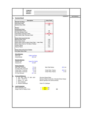
  • 1. COMPANY PROJECT SUBJECT 1. Summary Result Shackle and Sling Sling Stress Ratio Shackle Stress Ratio Padeye Dimensional Check Outside Radius Check Pin Hole Diameter Check Total Padeye Thickness Check Total Cheeck Plate Thickness Check Stress Check around the Hole Bearing Stress Check Shear Stress Check Shear Stress Check at Weld (Cheek Plate 1 - Main Plate) Shear Stress Check at The Base of Padeye Tension Failure Tearout Failure Stress Check at the End of Padeye Von Mises Stress Ratio Sling Selection Sling Type Cable Laid Sling Sling Diameter mm Shackle Selection Shackle Type Green Pin P-6033 Shackle WLL MT Padeye Selection Main Plate Thickness mm Main Plate Radius mm End Main Plate Thickness mm Cheek Plate 1 Thickness mm Cheek Plate 1 Radius mm Cheek Plate 2 Thickness mm Cheek Plate 2 Radius mm Pin Hole Diameter mm 2. Code and Reference a. TEP - 9001 - DBS - ST - BP5 - 0001 Structural Design Basis b. AISC - ASD 9th Ed. Manual of Steel Construction, Allowable Stress Design c. DNVGL - ST - N001 Marine Operation and marine warranty d. Sling Catalogue e. Shackle Catalaogue Green Pin Catalogue 3. Load Comparison SACS applicable Load = MT Design Load for Padeye Check = MT OK 0 0 221 289 700 75 400 75 350 597 600 60 0.72 0.75 0.37 0.40 1.12 0.88 0.59 0.56 NOT OK OK 23/09/2016 REFERENCE Description Unity Check 1.33 OK OK
  • 2. COMPANY PROJECT SUBJECT 23/09/2016 REFERENCE 4. Shackle and Sling Design Sling Force Maximum Sling Static Load (SSL) = MT = kN Dynamic Amplification Factor (DAF) = Design Basis Skew Factor (SKL) = Ch. 8.9.4 Consequences Factor (CF) = Load Factor = DAF x SKL x CF = Design Basis Ch. 8.9.4 Design Sling Load (DSL) = MT = kN Sling Selection Nominal Safety Factor for Sling (γsf) = DNVGL-ST-N0001 γf γc γr γw γm = 4.9 sect 16.4.3.1 2.3 γr γw = 4.5 DNVGL-ST-N0001 Lifting Factor γf = sect 16.4.4.1 Consequences Factor γc = sect 16.4.5.1 Sling Reduction Factor γr = (Maximum of γs and γb) sect 16.4.6.1 Termination Factor γs = sect 16.4.7 Bending Factor γb = sect 16.4.8 Sling Bending Diameter = mm Shackle Catalogue Wear Application Factor γw = sect 16.4.10 Material Factor γm = sect 16.4.9 The width available for the sling shall be not less than 1.3d (limited to 1.25d + 25 mm), where d is nominal DNVGL-ST-N0001 sling diameter in mm. sect 16.4.9.1 1.3d = mm OK 1.25d + 25 mm = mm Minimum Breaking Load MBL = SSL x γsf/CF = MT = kN Sling Type = Cable Laid Sling Sling Diameter = mm Sling MBL = MT Sling UC = > NOT OK Shackle Selection Shackle Type = Green Pin P-6033 Green Pin Catalogue Working Limit Load WLL = MT Derrated Factor φ = Pin Diameter b = mm Inside Jaw Width e = mm Inside Length f = mm Width Bow g = mm Criteria Shackle Selection DNVGL-ST-N0001 The shackle WLL should not be less than the static sling load sect 16.5.2 Working Limit Load WLL x φ = MT Maximum Sling Load P = MT WLL > P > OK The shackle dynamic load is to be less than the minimum of the following values DNVGL-ST-N0001 Shackle WLL x DAF x φ = MT sect 16.5.2 Shackle MBL / 3.0 = MT Shackle MBL = 5 x WLL = MT Green Pin Catalogue Shackle Unity Check = OK0.88 751 678.7608 600 746.6369 1131 3393.804 540 289 2461.5 1.33 700 215 315 380 1.10 1.50 3263.374 97% 375.7 386.25 32014 Max 1.30 1.30 1.77 1.25 1.77 1.00 1.30 1.43 858 8417 4.94 600 5886 1.10
  • 3. COMPANY PROJECT SUBJECT 23/09/2016 REFERENCE 5. Padeye Criteria Padeye Main plate height, Mp,h = mm pin hole diameter (dh) = mm radius of main plate (Rm) = mm radius of cheek plate 1 (Rc1) = mm radius of cheek plate 2 (Rc2) = mm main plate thickness (tm) = mm Yield Stress (Fy) of Main Plate = MPa Yield Stress (Fy) of Cheek Plate 1 = MPa Yield Stress (Fy) of Cheek Plate 2 = MPa cheek plate (1) thk, tce1 = mm cheek plate (1) thk, tce2 = mm DNVGL-ST-N0001 1. The outside radius of the padeye main plate shall be no less than the diameter of the pin hole. sect 16.9.5.1 Rm > dh --> OK 2. Pin-holes should be bored / reamed, and should be designed to suit the shackle proposed. sect 16.9.5.2 The pin hole diameter shall be 2 mm or 3% larger than the diameter of the shackle pin, whichever is the greater, up to a maximum of 6 mm b + 2 mm = mm Min Pin Hole Diameter mm b + (3% x b) = mm Max Pin Hole Diameter mm b + 6 mm = mm Status 3. The pad eye thickness at the hole shall not be less than 75% the inside width of the shackle sect 16.9.5.4 Rm + 2 Rc1 + 2 Rc2 = mm NOT OK 0.75 x e = mm 4. The total thicknesses of cheek plates on one side of the main plate should not exceed 100% sect 16.9.5.5 of the main plate thickness. The cheek plates should be symmetric either side of the main plate. tce1 + tce2 = mm OK tm = mm Padeye Design Forces Padeye Cordinate X = m Location of Padeye = Y = m Z = m X = m X = m Y = m Y = m Z = m Z = m Hook Cordinate (FEED) Hook Cordinate (SACS) -10.00 -15.00 48.80 -0.37 -0.47 74.56 -0.26 -0.03 80.32 Row C-2 75 217.0 221.5 221.0 225 236 75 75 325 325 325 75 0 221 221 OK 1000 221 400 350 0 DSF fz fy θ
  • 4. COMPANY PROJECT SUBJECT 23/09/2016 REFERENCE To FEED Cordinate To SACS Cordinate Lx = m Lx = m Ly = m Ly = m Lz = m Lz = m Lxy = (Lx 2 + Ly 2 )0.5 = m Lxy = (Lx 2 + Ly 2 )0.5 = m Lxyz = (Lx 2 + Ly 2 + Lz 2 )0.5 = m Lxy = (Lx 2 + Ly 2 + Lz 2 )0.5 = m β1 = deg β2 = deg β = β2 - β1 = deg Out of Plane Angle = degree Design Sling Force (DSF) = MT F (Out of Plane) = MAX DSF x sin β = MT = kN sect 16.9.3.1 3% x SSL Stress Check arround the hole Bearing Stress Check Bearing Force, Fb = kN Bearing Area, Ab = mm2 b x (t m + 2 t ce1 + 2t ce2 ) Bearing Stress, Fb/Ab = MPa Allowable Bearing Stress, 0.9 x Fy = MPa AISC Sect J8 UC = OK Shear Stress Check Shear Force, Fs = kN Shear Area, As (γ - γ) = mm2 [(R m - 0.5d h )t m +(R c1 - 0.5d h )2t ce1 +(R c2 - 0.5d h )2t ce2 ] x 2 Shear Stress, Fs/As = MPa Allowable Shear Stress, 0.4 x Fy = MPa AISC Sect F4 UC = OK Shear Stress Check at Weld (Cheek Plate 1 - Main Plate) Shear Force at Cheeck Plate 1, Fscheek 1 = kN SQRT( (DSF x t ce1 /(t m + 2 t ce1 + 2t ce2 )) 2 + (3% DSF) 2 ) DNVGL-ST-N0001 sect 16.9.5.6 73 130 0.56 2817 Cheek plate welds shall be proportioned and designed with due regard to possible uneven bearing across the padeye/cheek plate thickness due to combined nominal (3%) and actual lateral loads 48375 174 292.5 0.59 8417 115275 4.6 858 68.1 17 31 26 10 15 56 4.6 667.90 8417 18 36 10 15 32 60 fz fy θ γ γ β β C Mp h α α
  • 5. COMPANY PROJECT SUBJECT 23/09/2016 REFERENCE Fillet Weld Size, tw1 = mm Fillet yield Strength, Fyw = MPa (70 ksi) Weld Shear Area, Aw1 = mm2 0.707 x Π x R c1 x t w1 Shear Stress at Weld, Fscheek1/Aw1 = MPa Allowable Shear Stress, 0.3 x Fyw = MPa UC = OK Shear Stress Check at The Base of Padeye Shear Force, FsBase = kN DSF sin θ θ = 60 deg Shear Area, AsBase = mm2 Shear Stress = MPa Allowable Shear Stress, 0.4 x fy = MPa AISC Sect F4 UC = OK Tension and Tearout Failure Tension Force, Ft = kN Area at Cross Section, At (α - α) = mm2 [(R m - 0.5d h )t m +(R c1 - 0.5d h )2t ce1 +(R c2 - 0.5d h )2t ce2 ] x 2 Tension Stress, Ft/At = MPa Allowable Tensile Stress, 0.6 x fy = MPa AISC Sect D1 UC = OK Tearout Area, As (β - β) = mm2 t m ( Π R c1 x 2R m ) Tearout Stress, Fs/As = MPa Allowable Shear Stress, 0.45 x fy = MPa AISC Sect D3.1 UC = OK Stress Check at the end of padeye Main plate height, Mph = mm Main plate thickness, Mpt = mm Stiffener Plate 1 width, t1w = mm Stiffener Plate 1 thickness, t1t = mm Stiffener Plate 2 width, t2w = mm Stiffener Plate 2 thickness, t2t = mm Stiffener Plate 3 width, t3w = mm Stiffener Plate 3 thickness, t3t = mm Stiffener Plate 4 width, t4w = mm Stiffener Plate 4 thickness, t4t = mm Depth 1, d1 = mm Depth 2, d2 = mm Depth 3, d3 = mm Centre of pinhole to base of padeye, C = mm Neutral Axis, na = mm from top of stiffener 1 440 0 550 542.35 0.00 0.00 0.00 550.00 40.00 0 0.40 1000 60 400.00 40.00 0.00 73 195 0.37 142467 59 146 75000 97 130 0.75 8417 115275 482 27209 104 145 0.72 7289 35 taw taw
  • 6. COMPANY PROJECT SUBJECT 23/09/2016 REFERENCE About x - x axis About y - y axis Ixx = mm4 Iyy = mm4 Forces on Padeyes Centre of pinhole to base of padeye, C = mm Sling Load (DSF) = kN Out-pane Load (F) = kN Fx = F = kN Fy = DSF x Sin θ = kN Fz = DSF x Cos θ = kN Mx = = Nmm My = = Nmm Check Axial and Shear Stress along a section base of the padeye fs = fvx + fxy fvy = MPa fvx = MPa fbx = MPa fs = fby = MPa faz = MPa fvy = MPa fvx = MPa fbx = MPa fs = fby = MPa faz = MPa At Point B 121.49 0.00 84.35 121.49 0.00 30.94 7289 4208 3.58.E+09 3.67.E+08 At Point A 0.00 8.79 84.35 8.79 23.02 30.94 2.22.E+10 7.34.E+09 550 8417 668 668 TOTAL 98000 1.04.E+07 2.89.E+09 7.34.E+09 Area Main 60000 0 0.00.E+00 0.00.E+00 1.80.E+07 Area T4 22000 305 6.71.E+06 2.05.E+09 5.20.E+09 Area T3 0 0 0.00.E+00 0.00.E+00 0.00.E+00 2.12.E+09 Area T2 0 30 0.00.E+00 0.00.E+00 0.00.E+00 A (mm2 ) X(mm) AX (mm3 ) AX2 (mm4 ) Iyy (mm4 ) Area T1 16000 230 3.68.E+06 8.46.E+08 TOTAL 136000 7.38.E+07 1.73.E+10 5.01.E+09 Area Main 60000 500 3.00.E+07 1.08.E+08 5.00.E+09 Area T4 44000 980 4.31.E+07 8.43.E+09 5.87.E+06 Area T3 0 0 0.00.E+00 0.00.E+00 0.00.E+00 Area T2 0 0 0.00.E+00 0.00.E+00 0.00.E+00 Area T1 32000 20 6.40.E+05 8.73.E+09 4.27.E+06 A (mm2 ) Y(mm) AY (mm3 ) AY2 (mm4 ) Ixx (mm4 )
  • 7. COMPANY PROJECT SUBJECT 23/09/2016 REFERENCE fvy = MPa fvx = MPa fbx = MPa fs = fby = MPa faz = MPa fvy = MPa fvx = MPa fbx = MPa fs = fby = MPa faz = MPa fvy = MPa fvx = MPa fbx = MPa fs = fby = MPa faz = MPa fvy = MPa fvx = MPa fbx = MPa fs = fby = MPa faz = MPa Compute Von Mises combined stress, fc = [ (faz + fbx +fby)2 + 3fs2 ]0.5 Allowable combined stress, 0.66 x Fy = MPa At Point F 125.57 0.59 OK At Point D 0.00 0.00 OK At Point E 233.68 1.09 NOT OK At Point B 239.94 1.12 NOT OK At Point C 0.00 0.00 OK 214.50 fc (Mpa) UC Status At Point A 139.16 0.65 OK At Point F 0.00 8.79 70.67 8.79 23.02 30.94 At Point E 121.49 0.00 70.67 121.49 0.00 30.94 At Point D 0.00 0.00 0.00 0.00 0.00 0.00 At Point C 0.00 0.00 0.00 0.00 0.00 0.00