
Recomendados
Recomendados
Más contenido relacionado
La actualidad más candente
La actualidad más candente (20)
Similar a Shigley 13830681 solution mechanical engineering design shigley 7th edition
Similar a Shigley 13830681 solution mechanical engineering design shigley 7th edition (20)
Último
Último (20)
Shigley 13830681 solution mechanical engineering design shigley 7th edition
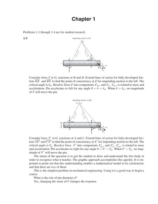
- 1. Chapter 1 D B G F Facc A E f f 1 1 cr C Impending motion to left Fcr Consider force F at G, reactions at B and D. Extend lines of action for fully-developed fric- tion DE and BE to find the point of concurrency at E for impending motion to the left. The critical angle is θcr. Resolve force F into components Facc and Fcr. Facc is related to mass and acceleration. Pin accelerates to left for any angle 0 < θ < θcr. When θ > θcr, no magnitude of F will move the pin. D B G FЈ FЈacc A EЈ иE f f 1 1 C d Impending motion to right Ј FcrЈ crЈ Consider force F at G, reactions at A and C. Extend lines of action for fully-developed fric- tion AE and C E to find the point of concurrency at E for impending motion to the left. The critical angle is θcr. Resolve force F into components Facc and Fcr. Facc is related to mass and acceleration. Pin accelerates to right for any angle 0 < θ < θcr. When θ > θcr, no mag- nitude of F will move the pin. The intent of the question is to get the student to draw and understand the free body in order to recognize what it teaches. The graphic approach accomplishes this quickly. It is im- portant to point out that this understanding enables a mathematical model to be constructed, and that there are two of them. This is the simplest problem in mechanical engineering. Using it is a good way to begin a course. What is the role of pin diameter d? Yes, changing the sense of F changes the response. Problems 1-1 through 1-4 are for student research. 1-5 shi20396_ch01.qxd 6/5/03 12:11 PM Page 1
- 2. 2 Solutions Manual • Instructor’s Solution Manual to Accompany Mechanical Engineering Design 1-6 (a) Fy = −F − f N cos θ + N sin θ = 0 (1) Fx = f N sin θ + N cos θ − T r = 0 F = N(sin θ − f cos θ) Ans. T = Nr( f sin θ + cos θ) Combining T = Fr 1 + f tan θ tan θ − f = KFr Ans. (2) (b) If T → ∞ detent self-locking tan θ − f = 0 ∴ θcr = tan−1 f Ans. (Friction is fully developed.) Check: If F = 10 lbf, f = 0.20, θ = 45◦, r = 2 in N = 10 −0.20 cos 45◦ + sin 45◦ = 17.68 lbf T r = 17.28(0.20 sin 45◦ + cos 45◦ ) = 15 lbf f N = 0.20(17.28) = 3.54 lbf θcr = tan−1 f = tan−1 (0.20) = 11.31◦ 11.31° < θ < 90° 1-7 (a) F = F0 + k(0) = F0 T1 = F0r Ans. (b) When teeth are about to clear F = F0 + kx2 From Prob. 1-6 T2 = Fr f tan θ + 1 tan θ − f T2 = r (F0 + kx2)( f tan θ + 1) tan θ − f Ans. 1-8 Given, F = 10 + 2.5x lbf, r = 2 in, h = 0.2 in, θ = 60◦ , f = 0.25, xi = 0, xf = 0.2 Fi = 10 lbf; Ff = 10 + 2.5(0.2) = 10.5 lbf Ans. x y F fN N T r shi20396_ch01.qxd 6/5/03 12:11 PM Page 2
- 3. Chapter 1 3 From Eq. (1) of Prob. 1-6 N = F − f cos θ + sin θ Ni = 10 −0.25 cos 60◦ + sin 60◦ = 13.49 lbf Ans. Nf = 10.5 10 13.49 = 14.17 lbf Ans. From Eq. (2) of Prob. 1-6 K = 1 + f tan θ tan θ − f = 1 + 0.25 tan 60◦ tan 60◦ − 0.25 = 0.967 Ans. Ti = 0.967(10)(2) = 19.33 lbf · in Tf = 0.967(10.5)(2) = 20.31 lbf · in 1-9 (a) Point vehicles Q = cars hour = v x = 42.1v − v2 0.324 Seek stationary point maximum dQ dv = 0 = 42.1 − 2v 0.324 ∴ v* = 21.05 mph Q* = 42.1(21.05) − 21.052 0.324 = 1367.6 cars/h Ans. (b) Q = v x + l = 0.324 v(42.1) − v2 + l v −1 Maximize Q with l = 10/5280 mi v Q 22.18 1221.431 22.19 1221.433 22.20 1221.435 ← 22.21 1221.435 22.22 1221.434 % loss of throughput 1368 − 1221 1221 = 12% Ans. xl 2 l 2 v x v shi20396_ch01.qxd 6/5/03 12:11 PM Page 3
- 4. 4 Solutions Manual • Instructor’s Solution Manual to Accompany Mechanical Engineering Design (c) % increase in speed 22.2 − 21.05 21.05 = 5.5% Modest change in optimal speed Ans. 1-10 This and the following problem may be the student’s first experience with a figure of merit. • Formulate fom to reflect larger figure of merit for larger merit. • Use a maximization optimization algorithm. When one gets into computer implementa- tion and answers are not known, minimizing instead of maximizing is the largest error one can make. FV = F1 sin θ − W = 0 FH = −F1 cos θ − F2 = 0 From which F1 = W/sin θ F2 = −W cos θ/sin θ fom = −S = −¢γ (volume) . = −¢γ(l1 A1 + l2 A2) A1 = F1 S = W S sin θ , l2 = l1 cos θ A2 = F2 S = W cos θ S sin θ fom = −¢γ l2 cos θ W S sin θ + l2W cos θ S sin θ = −¢γ Wl2 S 1 + cos2 θ cos θ sin θ Set leading constant to unity θ◦ fom 0 −∞ 20 −5.86 30 −4.04 40 −3.22 45 −3.00 50 −2.87 54.736 −2.828 60 −2.886 Check second derivative to see if a maximum, minimum, or point of inflection has been found. Or, evaluate fom on either side of θ*. θ* = 54.736◦ Ans. fom* = −2.828 Alternative: d dθ 1 + cos2 θ cos θ sin θ = 0 And solve resulting tran- scendental for θ*. shi20396_ch01.qxd 6/5/03 12:11 PM Page 4
- 5. Chapter 1 5 1-11 (a) x1 + x2 = X1 + e1 + X2 + e2 error = e = (x1 + x2) − (X1 + X2) = e1 + e2 Ans. (b) x1 − x2 = X1 + e1 − (X2 + e2) e = (x1 − x2) − (X1 − X2) = e1 − e2 Ans. (c) x1x2 = (X1 + e1)(X2 + e2) e = x1x2 − X1 X2 = X1e2 + X2e1 + e1e2 . = X1e2 + X2e1 = X1 X2 e1 X1 + e2 X2 Ans. (d) x1 x2 = X1 + e1 X2 + e2 = X1 X2 1 + e1/X1 1 + e2/X2 1 + e2 X2 −1 . = 1 − e2 X2 and 1 + e1 X1 1 − e2 X2 . = 1 + e1 X1 − e2 X2 e = x1 x2 − X1 X2 . = X1 X2 e1 X1 − e2 X2 Ans. 1-12 (a) x1 = √ 5 = 2.236 067 977 5 X1 = 2.23 3-correct digits x2 = √ 6 = 2.449 487 742 78 X2 = 2.44 3-correct digits x1 + x2 = √ 5 + √ 6 = 4.685 557 720 28 e1 = x1 − X1 = √ 5 − 2.23 = 0.006 067 977 5 e2 = x2 − X2 = √ 6 − 2.44 = 0.009 489 742 78 e = e1 + e2 = √ 5 − 2.23 + √ 6 − 2.44 = 0.015 557 720 28 Sum = x1 + x2 = X1 + X2 + e = 2.23 + 2.44 + 0.015 557 720 28 = 4.685 557 720 28 (Checks) Ans. (b) X1 = 2.24, X2 = 2.45 e1 = √ 5 − 2.24 = −0.003 932 022 50 e2 = √ 6 − 2.45 = −0.000 510 257 22 e = e1 + e2 = −0.004 442 279 72 Sum = X1 + X2 + e = 2.24 + 2.45 + (−0.004 442 279 72) = 4.685 557 720 28 Ans. shi20396_ch01.qxd 6/5/03 12:11 PM Page 5
- 6. 6 Solutions Manual • Instructor’s Solution Manual to Accompany Mechanical Engineering Design 1-13 (a) σ = 20(6.89) = 137.8 MPa (b) F = 350(4.45) = 1558 N = 1.558 kN (c) M = 1200 lbf · in (0.113) = 135.6 N · m (d) A = 2.4(645) = 1548 mm2 (e) I = 17.4 in4 (2.54)4 = 724.2 cm4 (f) A = 3.6(1.610)2 = 9.332 km2 (g) E = 21(1000)(6.89) = 144.69(103 ) MPa = 144.7 GPa (h) v = 45 mi/h (1.61) = 72.45 km/h (i) V = 60 in3 (2.54)3 = 983.2 cm3 = 0.983 liter 1-14 (a) l = 1.5/0.305 = 4.918 ft = 59.02 in (b) σ = 600/6.89 = 86.96 kpsi (c) p = 160/6.89 = 23.22 psi (d) Z = 1.84(105 )/(25.4)3 = 11.23 in3 (e) w = 38.1/175 = 0.218 lbf/in (f) δ = 0.05/25.4 = 0.00197 in (g) v = 6.12/0.0051 = 1200 ft/min (h) = 0.0021 in/in (i) V = 30/(0.254)3 = 1831 in3 1-15 (a) σ = 200 15.3 = 13.1 MPa (b) σ = 42(103 ) 6(10−2)2 = 70(106 ) N/m2 = 70 MPa (c) y = 1200(800)3 (10−3 )3 3(207)(6.4)(109)(10−2)4 = 1.546(10−2 ) m = 15.5 mm (d) θ = 1100(250)(10−3 ) 79.3(π/32)(25)4(109)(10−3)4 = 9.043(10−2 ) rad = 5.18◦ 1-16 (a) σ = 600 20(6) = 5 MPa (b) I = 1 12 8(24)3 = 9216 mm4 (c) I = π 64 324 (10−1 )4 = 5.147 cm4 (d) τ = 16(16) π(253)(10−3)3 = 5.215(106 ) N/m2 = 5.215 MPa shi20396_ch01.qxd 6/5/03 12:11 PM Page 6
- 7. Chapter 1 7 1-17 (a) τ = 120(103 ) (π/4)(202) = 382 MPa (b) σ = 32(800)(800)(10−3 ) π(32)3(10−3)3 = 198.9(106 ) N/m2 = 198.9 MPa (c) Z = π 32(36) (364 − 264 ) = 3334 mm3 (d) k = (1.6)4 (79.3)(10−3 )4 (109 ) 8(19.2)3(32)(10−3)3 = 286.8 N/m shi20396_ch01.qxd 6/5/03 12:11 PM Page 7
- 8. (b) f/(N x) = f/(69 · 10) = f/690 Eq. (2-9) ¯x = 8480 69 = 122.9 kcycles Eq. (2-10) sx = 1 104 600 − 84802 /69 69 − 1 1/2 = 30.3 kcycles Ans. x f fx f x2 f/(N x) 60 2 120 7200 0.0029 70 1 70 4900 0.0015 80 3 240 19200 0.0043 90 5 450 40500 0.0072 100 8 800 80000 0.0116 110 12 1320 145200 0.0174 120 6 720 86400 0.0087 130 10 1300 169000 0.0145 140 8 1120 156800 0.0116 150 5 750 112500 0.0174 160 2 320 51200 0.0029 170 3 510 86700 0.0043 180 2 360 64 800 0.0029 190 1 190 36100 0.0015 200 0 0 0 0 210 1 210 44100 0.0015 69 8480 1104 600 Chapter 2 2-1 (a) 0 60 210190 200180170160150140130120110100908070 2 4 6 8 10 12 shi20396_ch02.qxd 7/21/03 3:28 PM Page 8
- 9. Chapter 2 9 2-2 Data represents a 7-class histogram with N = 197. 2-3 Form a table: ¯x = 4548 58 = 78.4 kpsi sx = 359 088 − 45482 /58 58 − 1 1/2 = 6.57 kpsi From Eq. (2-14) f (x) = 1 6.57 √ 2π exp − 1 2 x − 78.4 6.57 2 x f fx f x2 64 2 128 8192 68 6 408 27744 72 6 432 31104 76 9 684 51984 80 19 1520 121600 84 10 840 70560 88 4 352 30976 92 2 184 16928 58 4548 359088 x f fx f x2 174 6 1044 181656 182 9 1638 298116 190 44 8360 1588400 198 67 13266 2626688 206 53 10918 2249108 214 12 2568 549552 220 6 1320 290400 197 39114 7789900 ¯x = 39 114 197 = 198.55 kpsi Ans. sx = 7 783 900 − 39 1142 /197 197 − 1 1/2 = 9.55 kpsi Ans. shi20396_ch02.qxd 7/21/03 3:28 PM Page 9
- 10. 10 Solutions Manual • Instructor’s Solution Manual to Accompany Mechanical Engineering Design 2-4 (a) y f fy f y2 y f/(Nw) f(y) g(y) 5.625 1 5.625 31.64063 5.625 0.072727 0.001262 0.000 295 5.875 0 0 0 5.875 0 0.008586 0.004 088 6.125 0 0 0 6.125 0 0.042038 0.031 194 6.375 3 19.125 121.9219 6.375 0.218182 0.148106 0.140 262 6.625 3 19.875 131.6719 6.625 0.218182 0.375493 0.393 667 6.875 6 41.25 283.5938 6.875 0.436364 0.685057 0.725 002 7.125 14 99.75 710.7188 7.125 1.018 182 0.899 389 0.915 128 7.375 15 110.625 815.8594 7.375 1.090 909 0.849 697 0.822 462 7.625 10 76.25 581.4063 7.625 0.727 273 0.577 665 0.544 251 7.875 2 15.75 124.0313 7.875 0.145455 0.282608 0.273 138 8.125 1 8.125 66.01563 8.125 0.072727 0.099492 0.10672 55 396.375 2866.859 For a normal distribution, ¯y = 396.375/55 = 7.207, sy = 2866.859 − (396.3752 /55) 55 − 1 1/2 = 0.4358 f (y) = 1 0.4358 √ 2π exp − 1 2 x − 7.207 0.4358 2 For a lognormal distribution, ¯x = ln 7.206 818 − ln √ 1 + 0.060 4742 = 1.9732, sx = ln √ 1 + 0.060 4742 = 0.0604 g(y) = 1 x(0.0604)( √ 2π) exp − 1 2 ln x − 1.9732 0.0604 2 (b) Histogram 0 0.2 0.4 0.6 0.8 1 1.2 5.63 5.88 6.13 6.38 6.63 6.88 log N 7.13 7.38 7.63 7.88 8.13 Data N LN f shi20396_ch02.qxd 7/21/03 3:28 PM Page 10
- 11. Chapter 2 11 2-5 Distribution is uniform in interval 0.5000 to 0.5008 in, range numbers are a = 0.5000, b = 0.5008 in. (a) Eq. (2-22) µx = a + b 2 = 0.5000 + 0.5008 2 = 0.5004 Eq. (2-23) σx = b − a 2 √ 3 = 0.5008 − 0.5000 2 √ 3 = 0.000 231 (b) PDF from Eq. (2-20) f (x) = 1250 0.5000 ≤ x ≤ 0.5008 in 0 otherwise (c) CDF from Eq. (2-21) F(x) = 0 x < 0.5000 (x − 0.5)/0.0008 0.5000 ≤ x ≤ 0.5008 1 x > 0.5008 If all smaller diameters are removed by inspection, a = 0.5002, b = 0.5008 µx = 0.5002 + 0.5008 2 = 0.5005 in ˆσx = 0.5008 − 0.5002 2 √ 3 = 0.000 173 in f (x) = 1666.7 0.5002 ≤ x ≤ 0.5008 0 otherwise F(x) = 0 x < 0.5002 1666.7(x − 0.5002) 0.5002 ≤ x ≤ 0.5008 1 x > 0.5008 2-6 Dimensions produced are due to tool dulling and wear. When parts are mixed, the distribution is uniform. From Eqs. (2-22) and (2-23), a = µx − √ 3s = 0.6241 − √ 3(0.000 581) = 0.6231 in b = µx + √ 3s = 0.6241 + √ 3(0.000 581) = 0.6251 in We suspect the dimension was 0.623 0.625 in Ans. shi20396_ch02.qxd 7/21/03 3:28 PM Page 11
- 12. 12 Solutions Manual • Instructor’s Solution Manual to Accompany Mechanical Engineering Design 2-7 F(x) = 0.555x − 33 mm (a) Since F(x) is linear, the distribution is uniform at x = a F(a) = 0 = 0.555(a) − 33 ∴ a = 59.46 mm. Therefore, at x = b F(b) = 1 = 0.555b − 33 ∴ b = 61.26 mm. Therefore, F(x) = 0 x < 59.46 mm 0.555x − 33 59.46 ≤ x ≤ 61.26 mm 1 x > 61.26 mm The PDF is dF/dx, thus the range numbers are: f (x) = 0.555 59.46 ≤ x ≤ 61.26 mm 0 otherwise Ans. From the range numbers, µx = 59.46 + 61.26 2 = 60.36 mm Ans. ˆσx = 61.26 − 59.46 2 √ 3 = 0.520 mm Ans. 1 (b) σ is an uncorrelated quotient ¯F = 3600 lbf, ¯A = 0.112 in2 CF = 300/3600 = 0.083 33, CA = 0.001/0.112 = 0.008 929 From Table 2-6, for σ ¯σ = µF µA = 3600 0.112 = 32 143 psi Ans. ˆσσ = 32 143 (0.083332 + 0.0089292 ) (1 + 0.0089292) 1/2 = 2694 psi Ans. Cσ = 2694/32 143 = 0.0838 Ans. Since F and A are lognormal, division is closed and σ is lognormal too. σ = LN(32 143, 2694) psi Ans. shi20396_ch02.qxd 7/21/03 3:28 PM Page 12
- 13. Chapter 2 13 2-8 Cramer’s rule a1 = y x2 xy x3 x x2 x2 x3 = y x3 − xy x2 x x3 − ( x2)2 Ans. a2 = x y x2 xy x x2 x2 x3 = x xy − y x2 x x3 − ( x2)2 Ans. Ϫ0.05 0 0.05 0.1 0.15 0.2 0.25 0.3 0 0.2 0.4 0.6 0.8 1 Data Regression x y x y x2 x3 xy 0 0.01 0 0 0 0.2 0.15 0.04 0.008 0.030 0.4 0.25 0.16 0.064 0.100 0.6 0.25 0.36 0.216 0.150 0.8 0.17 0.64 0.512 0.136 1.0 −0.01 1.00 1.000 −0.010 3.0 0.82 2.20 1.800 0.406 a1 = 1.040 714 a2 = −1.046 43 Ans. Data Regression x y y 0 0.01 0 0.2 0.15 0.166 286 0.4 0.25 0.248 857 0.6 0.25 0.247 714 0.8 0.17 0.162 857 1.0 −0.01 −0.005 71 shi20396_ch02.qxd 7/21/03 3:28 PM Page 13
- 14. 14 Solutions Manual • Instructor’s Solution Manual to Accompany Mechanical Engineering Design 2-9 0 20 40 60 80 100 120 140 0 100 200 Su SeЈ 300 400 Data Regression Data Regression Su Se Se S2 u Su Se 0 20.35675 60 30 39.08078 3600 1800 64 48 40.32905 4096 3072 65 29.5 40.64112 4225 1917.5 82 45 45.94626 6724 3690 101 51 51.87554 10201 5151 119 50 57.49275 14161 5950 120 48 57.80481 14400 5760 130 67 60.92548 16900 8710 134 60 62.17375 17956 8040 145 64 65.60649 21025 9280 180 84 76.52884 32400 15120 195 78 81.20985 38025 15210 205 96 84.33052 42025 19680 207 87 84.95466 42849 18009 210 87 85.89086 44100 18270 213 75 86.82706 45369 15975 225 99 90.57187 50625 22275 225 87 90.57187 50625 19575 227 116 91.196 51529 26332 230 105 92.1322 52900 24150 238 109 94.62874 56644 25942 242 106 95.87701 58564 25652 265 105 103.0546 70225 27825 280 96 107.7356 78400 26880 295 99 112.4166 87025 29205 325 114 121.7786 105625 37050 325 117 121.7786 105625 38025 355 122 131.1406 126025 43310 5462 2274.5 1251868 501855.5 m = 0.312067 b = 20.35675 Ans. shi20396_ch02.qxd 7/21/03 3:28 PM Page 14
- 15. Chapter 2 15 2-10 E = y − a0 − a2x2 2 ∂E ∂a0 = −2 y − a0 − a2x2 = 0 y − na0 − a2 x2 = 0 ⇒ y = na0 + a2 x2 ∂E ∂a2 = 2 y − a0 − a2x2 (2x) = 0 ⇒ xy = a0 x + a2 x3 Ans. Cramer’s rule a0 = y x2 xy x3 n x2 x x3 = x3 y − x2 xy n x3 − x x2 a2 = n y x xy n x2 x x3 = n xy − x y n x3 − x x2 a0 = 800 000(56) − 12 000(2400) 4(800 000) − 200(12 000) = 20 a2 = 4(2400) − 200(56) 4(800 000) − 200(12 000) = −0.002 Data Regression 0 5 10 15 y x 20 25 0 20 40 60 80 100 Data Regression x y y x2 x3 xy 20 19 19.2 400 8000 380 40 17 16.8 1600 64000 680 60 13 12.8 3600 216000 780 80 7 7.2 6400 512000 560 200 56 12000 800000 2400 shi20396_ch02.qxd 7/21/03 3:28 PM Page 15
- 16. 16 Solutions Manual • Instructor’s Solution Manual to Accompany Mechanical Engineering Design 2-11 Data Regression x y y x2 y2 xy x − ¯x (x − ¯x)2 0.2 7.1 7.931803 0.04 50.41 1.42 −0.633333 0.401111111 0.4 10.3 9.884918 0.16 106.09 4.12 −0.433333 0.187777778 0.6 12.1 11.838032 0.36 146.41 7.26 −0.233333 0.054444444 0.8 13.8 13.791147 0.64 190.44 11.04 −0.033333 0.001111111 1 16.2 15.744262 1.00 262.44 16.20 0.166666 0.027777778 2 25.2 25.509836 4.00 635.04 50.40 1.166666 1.361111111 5 84.7 6.2 1390.83 90.44 0 2.033333333 ˆm = k = 6(90.44) − 5(84.7) 6(6.2) − (5)2 = 9.7656 ˆb = Fi = 84.7 − 9.7656(5) 6 = 5.9787 (a) ¯x = 5 6 ; ¯y = 84.7 6 = 14.117 Eq. (2-37) syx = 1390.83 − 5.9787(84.7) − 9.7656(90.44) 6 − 2 = 0.556 Eq. (2-36) sˆb = 0.556 1 6 + (5/6)2 2.0333 = 0.3964 lbf Fi = (5.9787, 0.3964) lbf Ans. F x0 5 10 15 20 25 30 0 10.5 1.5 2 2.5 Data Regression shi20396_ch02.qxd 7/21/03 3:28 PM Page 16
- 17. Chapter 2 17 (b) Eq. (2-35) s ˆm = 0.556 √ 2.0333 = 0.3899 lbf/in k = (9.7656, 0.3899) lbf/in Ans. 2-12 The expression = δ/l is of the form x/y. Now δ = (0.0015, 0.000 092) in, unspecified distribution; l = (2.000, 0.0081) in, unspecified distribution; Cx = 0.000 092/0.0015 = 0.0613 Cy = 0.0081/2.000 = 0.000 75 From Table 2-6, ¯ = 0.0015/2.000 = 0.000 75 ˆσ = 0.000 75 0.06132 + 0.004 052 1 + 0.004 052 1/2 = 4.607(10−5 ) = 0.000 046 We can predict ¯ and ˆσ but not the distribution of . 2-13 σ = E = (0.0005, 0.000 034) distribution unspecified; E = (29.5, 0.885) Mpsi, distribution unspecified; Cx = 0.000 034/0.0005 = 0.068, Cy = 0.0885/29.5 = 0.030 σ is of the form x, y Table 2-6 ¯σ = ¯ ¯E = 0.0005(29.5)106 = 14 750 psi ˆσσ = 14 750(0.0682 + 0.0302 + 0.0682 + 0.0302 )1/2 = 1096.7 psi Cσ = 1096.7/14 750 = 0.074 35 2-14 δ = Fl AE F = (14.7, 1.3) kip, A = (0.226, 0.003)in2 , l = (1.5, 0.004) in, E = (29.5, 0.885) Mpsi dis- tributions unspecified. CF = 1.3/14.7 = 0.0884; CA = 0.003/0.226 = 0.0133; Cl = 0.004/1.5 = 0.00267; CE = 0.885/29.5 = 0.03 Mean of δ: δ = Fl AE = Fl 1 A 1 E shi20396_ch02.qxd 7/21/03 3:28 PM Page 17
- 18. 18 Solutions Manual • Instructor’s Solution Manual to Accompany Mechanical Engineering Design From Table 2-6, ¯δ = ¯F ¯l(1/ ¯A)(1/ ¯E) ¯δ = 14 700(1.5) 1 0.226 1 29.5(106) = 0.003 31 in Ans. For the standard deviation, using the first-order terms in Table 2-6, ˆσδ . = ¯F ¯l ¯A ¯E C2 F + C2 l + C2 A + C2 E 1/2 = ¯δ C2 F + C2 l + C2 A + C2 E 1/2 ˆσδ = 0.003 31(0.08842 + 0.002672 + 0.01332 + 0.032 )1/2 = 0.000 313 in Ans. COV Cδ = 0.000 313/0.003 31 = 0.0945 Ans. Force COV dominates. There is no distributional information on δ. 2-15 M = (15000, 1350) lbf · in, distribution unspecified; d = (2.00, 0.005) in distribution unspecified. σ = 32M πd3 , CM = 1350 15 000 = 0.09, Cd = 0.005 2.00 = 0.0025 σ is of the form x/y, Table 2-6. Mean: ¯σ = 32 ¯M πd3 . = 32 ¯M π ¯d3 = 32(15 000) π(23) = 19 099 psi Ans. Standard Deviation: ˆσσ = ¯σ C2 M + C2 d3 1 + C2 d3 1/2 From Table 2-6, Cd3 . = 3Cd = 3(0.0025) = 0.0075 ˆσσ = ¯σ C2 M + (3Cd)2 (1 + (3Cd))2 1/2 = 19 099[(0.092 + 0.00752 )/(1 + 0.00752 )]1/2 = 1725 psi Ans. COV: Cσ = 1725 19 099 = 0.0903 Ans. Stress COV dominates. No information of distribution of σ. shi20396_ch02.qxd 7/21/03 3:28 PM Page 18
- 19. Chapter 2 19 2-16 Fraction discarded is α + β. The area under the PDF was unity. Having discarded α + β fraction, the ordinates to the truncated PDF are multiplied by a. a = 1 1 − (α + β) New PDF, g(x), is given by g(x) = f (x)/[1 − (α + β)] x1 ≤ x ≤ x2 0 otherwise More formal proof: g(x) has the property 1 = x2 x1 g(x) dx = a x2 x1 f (x) dx 1 = a ∞ −∞ f (x) dx − x1 0 f (x) dx − ∞ x2 f (x) dx 1 = a {1 − F(x1) − [1 − F(x2)]} a = 1 F(x2) − F(x1) = 1 (1 − β) − α = 1 1 − (α + β) 2-17 (a) d = U[0.748, 0.751] µd = 0.751 + 0.748 2 = 0.7495 in ˆσd = 0.751 − 0.748 2 √ 3 = 0.000 866 in f (x) = 1 b − a = 1 0.751 − 0.748 = 333.3 in−1 F(x) = x − 0.748 0.751 − 0.748 = 333.3(x − 0.748) x1 f(x) x x2 ␣  shi20396_ch02.qxd 7/21/03 3:28 PM Page 19
- 20. 20 Solutions Manual • Instructor’s Solution Manual to Accompany Mechanical Engineering Design (b) F(x1) = F(0.748) = 0 F(x2) = (0.750 − 0.748)333.3 = 0.6667 If g(x) is truncated, PDF becomes g(x) = f (x) F(x2) − F(x1) = 333.3 0.6667 − 0 = 500 in−1 µx = a + b 2 = 0.748 + 0.750 2 = 0.749 in ˆσx = b − a 2 √ 3 = 0.750 − 0.748 2 √ 3 = 0.000 577 in 2-18 From Table A-10, 8.1% corresponds to z1 = −1.4 and 5.5% corresponds to z2 = +1.6. k1 = µ + z1 ˆσ k2 = µ + z2 ˆσ From which µ = z2k1 − z1k2 z2 − z1 = 1.6(9) − (−1.4)11 1.6 − (−1.4) = 9.933 ˆσ = k2 − k1 z2 − z1 = 11 − 9 1.6 − (−1.4) = 0.6667 The original density function is f (k) = 1 0.6667 √ 2π exp − 1 2 k − 9.933 0.6667 2 Ans. 2-19 From Prob. 2-1, µ = 122.9 kcycles and ˆσ = 30.3 kcycles. z10 = x10 − µ ˆσ = x10 − 122.9 30.3 x10 = 122.9 + 30.3z10 From Table A-10, for 10 percent failure, z10 = −1.282 x10 = 122.9 + 30.3(−1.282) = 84.1 kcycles Ans. 0.748 g(x) ϭ 500 x f(x) ϭ 333.3 0.749 0.750 0.751 shi20396_ch02.qxd 7/21/03 3:28 PM Page 20
- 21. Chapter 2 21 2-20 x f fx f x2 x f/(Nw) f(x) 60 2 120 7200 60 0.002899 0.000399 70 1 70 4900 70 0.001449 0.001206 80 3 240 19200 80 0.004348 0.003009 90 5 450 40500 90 0.007246 0.006204 100 8 800 80000 100 0.011594 0.010567 110 12 1320 145200 110 0.017391 0.014871 120 6 720 86400 120 0.008696 0.017292 130 10 1300 169000 130 0.014493 0.016612 140 8 1120 156800 140 0.011594 0.013185 150 5 750 112500 150 0.007246 0.008647 160 2 320 51200 160 0.002899 0.004685 170 3 510 86700 170 0.004348 0.002097 180 2 360 64800 180 0.002899 0.000776 190 1 190 36100 190 0.001449 0.000237 200 0 0 0 200 0 5.98E-05 210 1 210 44100 210 0.001449 1.25E-05 69 8480 ¯x = 122.8986 sx = 22.88719 x f/(Nw) f(x) x f/(Nw) f(x) 55 0 0.000214 145 0.011594 0.010935 55 0.002899 0.000214 145 0.007246 0.010935 65 0.002899 0.000711 155 0.007246 0.006518 65 0.001449 0.000711 155 0.002899 0.006518 75 0.001449 0.001951 165 0.002899 0.00321 75 0.004348 0.001951 165 0.004348 0.00321 85 0.004348 0.004425 175 0.004348 0.001306 85 0.007246 0.004425 175 0.002899 0.001306 95 0.007246 0.008292 185 0.002899 0.000439 95 0.011594 0.008292 185 0.001449 0.000439 105 0.011594 0.012839 195 0.001449 0.000122 105 0.017391 0.012839 195 0 0.000122 115 0.017391 0.016423 205 0 2.8E-05 115 0.008696 0.016423 205 0.001499 2.8E-05 125 0.008696 0.017357 215 0.001499 5.31E-06 125 0.014493 0.017357 215 0 5.31E-06 135 0.014493 0.015157 135 0.011594 0.015157 shi20396_ch02.qxd 7/21/03 3:28 PM Page 21
- 22. 22 Solutions Manual • Instructor’s Solution Manual to Accompany Mechanical Engineering Design 2-21 x f fx f x2 f/(Nw) f (x) 174 6 1044 181656 0.003807 0.001642 182 9 1638 298116 0.005711 0.009485 190 44 8360 1588400 0.027919 0.027742 198 67 13266 2626668 0.042513 0.041068 206 53 10918 2249108 0.033629 0.030773 214 12 2568 549552 0.007614 0.011671 222 6 1332 295704 0.003807 0.002241 1386 197 39126 7789204 ¯x = 198.6091 sx = 9.695071 x f/(Nw) f (x) 170 0 0.000529 170 0.003807 0.000529 178 0.003807 0.004297 178 0.005711 0.004297 186 0.005711 0.017663 186 0.027919 0.017663 194 0.027919 0.036752 194 0.042513 0.036752 202 0.042513 0.038708 202 0.033629 0.038708 210 0.033629 0.020635 210 0.007614 0.020635 218 0.007614 0.005568 218 0.003807 0.005568 226 0.003807 0.00076 226 0 0.00076 Data PDF 0 0.005 0.01 0.015 0.02 0.025 0.03 0.035 0.04 0.045 150 170 190 210 x 230 f Histogram PDF 0 0.002 0.004 0.006 0.008 0.01 0.012 0.014 0.016 0.018 f x 0.02 0 50 100 150 200 250 shi20396_ch02.qxd 7/21/03 3:28 PM Page 22
- 23. Chapter 2 23 2-22 x f fx f x2 f/(Nw) f(x) 64 2 128 8192 0.008621 0.00548 68 6 408 27744 0.025862 0.017299 72 6 432 31104 0.025862 0.037705 76 9 684 51984 0.038793 0.056742 80 19 1520 121600 0.081897 0.058959 84 10 840 70560 0.043103 0.042298 88 4 352 30976 0.017241 0.020952 92 2 184 16928 0.008621 0.007165 624 58 4548 359088 ¯x = 78.41379 sx = 6.572229 x f/(Nw) f(x) x f/(Nw) f(x) 62 0 0.002684 82 0.081897 0.052305 62 0.008621 0.002684 82 0.043103 0.052305 66 0.008621 0.010197 86 0.043103 0.03118 66 0.025862 0.010197 86 0.017241 0.03118 70 0.025862 0.026749 90 0.017241 0.012833 70 0.025862 0.026749 90 0.008621 0.012833 74 0.025862 0.048446 94 0.008621 0.003647 74 0.038793 0.048446 94 0 0.003647 78 0.038793 0.060581 78 0.081897 0.060581 2-23 ¯σ = 4 ¯P πd2 = 4(40) π(12) = 50.93 kpsi ˆσσ = 4 ˆσP πd2 = 4(8.5) π(12) = 10.82 kpsi ˆσsy = 5.9 kpsi Data PDF x0 0.01 0.02 0.03 0.04 0.05 0.06 0.07 0.08 0.09 60 70 80 90 100 f shi20396_ch02.qxd 7/21/03 3:28 PM Page 23
- 24. 24 Solutions Manual • Instructor’s Solution Manual to Accompany Mechanical Engineering Design For no yield, m = Sy − σ ≥ 0 z = m − µm ˆσm = 0 − µm ˆσm = − µm ˆσm µm = ¯Sy − ¯σ = 27.47 kpsi, ˆσm = ˆσ2 σ + ˆσ2 Sy 1/2 = 12.32 kpsi z = −27.47 12.32 = −2.230 From Table A-10, pf = 0.0129 R = 1 − pf = 1 − 0.0129 = 0.987 Ans. 2-24 For a lognormal distribution, Eq. (2-18) µy = ln µx − ln 1 + C2 x Eq. (2-19) ˆσy = ln 1 + C2 x From Prob. (2-23) µm = ¯Sy − ¯σ = µx µy = ln ¯Sy − ln 1 + C2 Sy − ln ¯σ − ln 1 + C2 σ = ln ¯Sy ¯σ 1 + C2 σ 1 + C2 Sy ˆσy = ln 1 + C2 Sy + ln 1 + C2 σ 1/2 = ln 1 + C2 Sy 1 + C2 σ z = − µ ˆσ = − ln ¯Sy ¯σ 1 + C2 σ 1 + C2 Sy ln 1 + C2 Sy 1 + C2 σ ¯σ = 4 ¯P πd2 = 4(30) π(12) = 38.197 kpsi ˆσσ = 4 ˆσP πd2 = 4(5.1) π(12) = 6.494 kpsi Cσ = 6.494 38.197 = 0.1700 CSy = 3.81 49.6 = 0.076 81 0 m shi20396_ch02.qxd 7/21/03 3:28 PM Page 24
- 25. Chapter 2 25 z = − ln 49.6 38.197 1 + 0.1702 1 + 0.076 812 ln (1 + 0.076 812)(1 + 0.1702) = −1.470 From Table A-10 pf = 0.0708 R = 1 − pf = 0.929 Ans. 2-25 (a) a = 1.000 ± 0.001 in b = 2.000 ± 0.003 in c = 3.000 ± 0.005 in d = 6.020 ± 0.006 in ¯w = d − a − b − c = 6.020 − 1 − 2 − 3 = 0.020 in tw = tall = 0.001 + 0.003 + 0.005 + 0.006 = 0.015 in w = 0.020 ± 0.015 in Ans. (b) ¯w = 0.020 ˆσw = ˆσ2 all = 0.001 √ 3 2 + 0.003 √ 3 2 + 0.005 √ 3 2 + 0.006 √ 3 2 = 0.004 86 → 0.005 in (uniform) w = 0.020 ± 0.005 in Ans. 2-26 V + V = (a + a)(b + b)(c + c) V + V = abc + bc a + ac b + ab c + small higher order terms V ¯V . = a a + b b + c c Ans. ¯V = ¯a ¯b¯c = 1.25(1.875)(2.75) = 6.4453 in3 V ¯V = 0.001 1.250 + 0.002 1.875 + 0.003 2.750 = 0.00296 V = V ¯V ¯V = 0.00296(6.4453) = 0.0191 in3 Lower range number: ¯V − V = 6.4453 − 0.0191 = 6.4262 in3 Ans. Upper range number: ¯V + V = 6.4453 + 0.0191 = 6.4644 in3 Ans. shi20396_ch02.qxd 7/21/03 3:28 PM Page 25
- 26. 26 Solutions Manual • Instructor’s Solution Manual to Accompany Mechanical Engineering Design 2-27 (a) wmax = 0.014 in, wmin = 0.004 in ¯w = (0.014 + 0.004)/2 = 0.009 in w = 0.009 ± 0.005 in ¯w = ¯x − ¯y = ¯a − ¯b − ¯c 0.009 = ¯a − 0.042 − 1.000 ¯a = 1.051 in tw = tall 0.005 = ta + 0.002 + 0.002 ta = 0.005 − 0.002 − 0.002 = 0.001 in a = 1.051 ± 0.001 in Ans. (b) ˆσw = ˆσ2 all = ˆσ2 a + ˆσ2 b + ˆσ2 c ˆσ2 a = ˆσ2 w − ˆσ2 b − ˆσ2 c = 0.005 √ 3 2 − 0.002 √ 3 2 − 0.002 √ 3 2 ˆσ2 a = 5.667(10−6 ) ˆσa = 5.667(10−6) = 0.00238 in ¯a = 1.051 in, ˆσa = 0.00238 in Ans. 2-28 Choose 15 mm as basic size, D, d. Table 2-8: fit is designated as 15H7/h6. From Table A-11, the tolerance grades are D = 0.018 mm and d = 0.011 mm. Hole: Eq. (2-38) Dmax = D + D = 15 + 0.018 = 15.018 mm Ans. Dmin = D = 15.000 mm Ans. Shaft: From Table A-12, fundamental deviation δF = 0. From Eq. (2-39) dmax = d + δF = 15.000 + 0 = 15.000 mm Ans. dmin = d + δR − d = 15.000 + 0 − 0.011 = 14.989 mm Ans. 2-29 Choose 45 mm as basic size. Table 2-8 designates fit as 45H7/s6. From Table A-11, the tolerance grades are D = 0.025 mm and d = 0.016 mm Hole: Eq. (2-38) Dmax = D + D = 45.000 + 0.025 = 45.025 mm Ans. Dmin = D = 45.000 mm Ans. a c b w shi20396_ch02.qxd 7/21/03 3:28 PM Page 26
- 27. Chapter 2 27 Shaft: From Table A-12, fundamental deviation δF = +0.043 mm. From Eq. (2-40) dmin = d + δF = 45.000 + 0.043 = 45.043 mm Ans. dmax = d + δF + d = 45.000 + 0.043 + 0.016 = 45.059 mm Ans. 2-30 Choose 50 mm as basic size. From Table 2-8 fit is 50H7/g6. From Table A-11, the tolerance grades are D = 0.025 mm and d = 0.016 mm. Hole: Dmax = D + D = 50 + 0.025 = 50.025 mm Ans. Dmin = D = 50.000 mm Ans. Shaft: From Table A-12 fundamental deviation = −0.009 mm dmax = d + δF = 50.000 + (−0.009) = 49.991 mm Ans. dmin = d + δF − d = 50.000 + (−0.009) − 0.016 = 49.975 mm 2-31 Choose the basic size as 1.000 in. From Table 2-8, for 1.0 in, the fit is H8/f7. From Table A-13, the tolerance grades are D = 0.0013 in and d = 0.0008 in. Hole: Dmax = D + ( D)hole = 1.000 + 0.0013 = 1.0013 in Ans. Dmin = D = 1.0000 in Ans. Shaft: From Table A-14: Fundamental deviation = −0.0008 in dmax = d + δF = 1.0000 + (−0.0008) = 0.9992 in Ans. dmin = d + δF − d = 1.0000 + (−0.0008) − 0.0008 = 0.9984 in Ans. Alternatively, dmin = dmax − d = 0.9992 − 0.0008 = 0.9984 in. Ans. 2-32 Do = W + Di + W ¯Do = ¯W + ¯Di + ¯W = 0.139 + 3.734 + 0.139 = 4.012 in tDo = tall = 0.004 + 0.028 + 0.004 = 0.036 in Do = 4.012 ± 0.036 in Ans. Do WDiW shi20396_ch02.qxd 7/21/03 3:28 PM Page 27
- 28. 28 Solutions Manual • Instructor’s Solution Manual to Accompany Mechanical Engineering Design 2-33 Do = Di + 2W ¯Do = ¯Di + 2 ¯W = 208.92 + 2(5.33) = 219.58 mm tDo = all t = tDi + 2tw = 1.30 + 2(0.13) = 1.56 mm Do = 219.58 ± 1.56 mm Ans. 2-34 Do = Di + 2W ¯Do = ¯Di + 2 ¯W = 3.734 + 2(0.139) = 4.012 mm tDo = all t2 = t2 Do + (2 tw)2 1/2 = [0.0282 + (2)2 (0.004)2 ]1/2 = 0.029 in Do = 4.012 ± 0.029 in Ans. 2-35 Do = Di + 2W ¯Do = ¯Di + 2 ¯W = 208.92 + 2(5.33) = 219.58 mm tDo = all t2 = [1.302 + (2)2 (0.13)2 ]1/2 = 1.33 mm Do = 219.58 ± 1.33 mm Ans. 2-36 (a) w = F − W ¯w = ¯F − ¯W = 0.106 − 0.139 = −0.033 in tw = all t = 0.003 + 0.004 tw = 0.007 in wmax = ¯w + tw = −0.033 + 0.007 = −0.026 in wmin = ¯w − tw = −0.033 − 0.007 = −0.040 in The minimum “squeeze” is 0.026 in. Ans. w W F shi20396_ch02.qxd 7/21/03 3:28 PM Page 28
- 29. Chapter 2 29 (b) Y = 3.992 ± 0.020 in Do + w − Y = 0 w = Y − ¯Do ¯w = ¯Y − ¯Do = 3.992 − 4.012 = −0.020 in tw = all t = tY + tDo = 0.020 + 0.036 = 0.056 in w = −0.020 ± 0.056 in wmax = 0.036 in wmin = −0.076 in O-ring is more likely compressed than free prior to assembly of the end plate. 2-37 (a) Figure defines w as gap. The O-ring is “squeezed” at least 0.75 mm. (b) From the figure, the stochastic equation is: Do + w = Y or, w = Y − Do ¯w = ¯Y − ¯Do = 218.48 − 219.58 = −1.10 mm tw = all t = tY + tDo = 1.10 + 0.34 = 1.44 mm wmax = ¯w + tw = −1.10 + 1.44 = 0.34 mm wmin = ¯w − tw = −1.10 − 1.44 = −2.54 mm The O-ring is more likely to be circumferentially compressed than free prior to as- sembly of the end plate. Ymax = ¯Do = 219.58 mm Ymin = max[0.99 ¯Do, ¯Do − 1.52] = max[0.99(219.58, 219.58 − 1.52)] = 217.38 mm Y = 218.48 ± 1.10 mm Y Do w w = F − W ¯w = ¯F − ¯W = 4.32 − 5.33 = −1.01 mm tw = all t = tF + tW = 0.13 + 0.13 = 0.26 mm wmax = ¯w + tw = −1.01 + 0.26 = −0.75 mm wmin = ¯w − tw = −1.01 − 0.26 = −1.27 mm w W F Ymax = ¯Do = 4.012 in Ymin = max[0.99 ¯Do, ¯Do − 0.06] = max[3.9719, 3.952] = 3.972 in Y Do w shi20396_ch02.qxd 8/6/03 11:07 AM Page 29
- 30. 30 Solutions Manual • Instructor’s Solution Manual to Accompany Mechanical Engineering Design 2-38 wmax = −0.020 in, wmin = −0.040 in ¯w = 1 2 (−0.020 + (−0.040)) = −0.030 in tw = 1 2 (−0.020 − (−0.040)) = 0.010 in b = 0.750 ± 0.001 in c = 0.120 ± 0.005 in d = 0.875 ± 0.001 in ¯w = ¯a − ¯b − ¯c − ¯d −0.030 = ¯a − 0.875 − 0.120 − 0.750 ¯a = 0.875 + 0.120 + 0.750 − 0.030 ¯a = 1.715 in Absolute: tw = all t = 0.010 = ta + 0.001 + 0.005 + 0.001 ta = 0.010 − 0.001 − 0.005 − 0.001 = 0.003 in a = 1.715 ± 0.003 in Ans. Statistical: For a normal distribution of dimensions t2 w = all t2 = t2 a + t2 b + t2 c + t2 d ta = t2 w − t2 b − t2 c − t2 d 1/2 = (0.0102 − 0.0012 − 0.0052 − 0.0012 )1/2 = 0.0085 a = 1.715 ± 0.0085 in Ans. 2-39 x n nx nx2 93 19 1767 164 311 95 25 2375 225 625 97 38 3685 357 542 99 17 1683 166 617 101 12 1212 122 412 103 10 1030 106 090 105 5 525 55 125 107 4 428 45 796 109 4 436 47 524 111 2 222 24 624 136 13364 1315 704 ¯x = 13 364/136 = 98.26 kpsi sx = 1 315 704 − 13 3642 /136 135 1/2 = 4.30 kpsi b c w d a shi20396_ch02.qxd 7/21/03 3:28 PM Page 30
- 31. Chapter 2 31 Under normal hypothesis, z0.01 = (x0.01 − 98.26)/4.30 x0.01 = 98.26 + 4.30z0.01 = 98.26 + 4.30(−2.3267) = 88.26 . = 88.3 kpsi Ans. 2-40 From Prob. 2-39, µx = 98.26 kpsi, and ˆσx = 4.30 kpsi. Cx = ˆσx/µx = 4.30/98.26 = 0.043 76 From Eqs. (2-18) and (2-19), µy = ln(98.26) − 0.043 762 /2 = 4.587 ˆσy = ln(1 + 0.043 762) = 0.043 74 For a yield strength exceeded by 99% of the population, z0.01 = (ln x0.01 − µy)/ˆσy ⇒ ln x0.01 = µy + ˆσyz0.01 From Table A-10, for 1% failure, z0.01 = −2.326. Thus, ln x0.01 = 4.587 + 0.043 74(−2.326) = 4.485 x0.01 = 88.7 kpsi Ans. The normal PDF is given by Eq. (2-14) as f (x) = 1 4.30 √ 2π exp − 1 2 x − 98.26 4.30 2 For the lognormal distribution, from Eq. (2-17), defining g(x), g(x) = 1 x(0.043 74) √ 2π exp − 1 2 ln x − 4.587 0.043 74 2 x (kpsi) f/(Nw) f (x) g(x) x (kpsi) f/(Nw) f (x) g(x) 92 0.00000 0.03215 0.03263 102 0.03676 0.06356 0.06134 92 0.06985 0.03215 0.03263 104 0.03676 0.03806 0.03708 94 0.06985 0.05680 0.05890 104 0.01838 0.03806 0.03708 94 0.09191 0.05680 0.05890 106 0.01838 0.01836 0.01869 96 0.09191 0.08081 0.08308 106 0.01471 0.01836 0.01869 96 0.13971 0.08081 0.08308 108 0.01471 0.00713 0.00793 98 0.13971 0.09261 0.09297 108 0.01471 0.00713 0.00793 98 0.06250 0.09261 0.09297 110 0.01471 0.00223 0.00286 100 0.06250 0.08548 0.08367 110 0.00735 0.00223 0.00286 100 0.04412 0.08548 0.08367 112 0.00735 0.00056 0.00089 102 0.04412 0.06356 0.06134 112 0.00000 0.00056 0.00089 Note: rows are repeated to draw histogram shi20396_ch02.qxd 7/21/03 3:28 PM Page 31
- 32. 32 Solutions Manual • Instructor’s Solution Manual to Accompany Mechanical Engineering Design The normal and lognormal are almost the same. However the data is quite skewed and perhaps a Weibull distribution should be explored. For a method of establishing the Weibull parameters see Shigley, J. E., and C. R. Mischke, Mechanical Engineering Design, McGraw-Hill, 5th ed., 1989, Sec. 4-12. 2-41 Let x = (S fe)104 x0 = 79 kpsi, θ = 86.2 kpsi, b = 2.6 Eq. (2-28) ¯x = x0 + (θ − x0) (1 + 1/b) ¯x = 79 + (86.2 − 79) (1 + 1/2.6) = 79 + 7.2 (1.38) From Table A-34, (1.38) = 0.88854 ¯x = 79 + 7.2(0.888 54) = 85.4 kpsi Ans. Eq. (2-29) ˆσx = (θ − x0)[ (1 + 2/b) − 2 (1 + 1/b)]1/2 = (86.2 − 79)[ (1 + 2/2.6) − 2 (1 + 1/2.6)]1/2 = 7.2[0.923 76 − 0.888 542 ]1/2 = 2.64 kpsi Ans. Cx = ˆσx ¯x = 2.64 85.4 = 0.031 Ans. 2-42 x = Sut x0 = 27.7, θ = 46.2, b = 4.38 µx = 27.7 + (46.2 − 27.7) (1 + 1/4.38) = 27.7 + 18.5 (1.23) = 27.7 + 18.5(0.910 75) = 44.55 kpsi Ans. f(x) g(x) Histogram 0 0.02 0.04 0.06 0.08 0.1 0.12 0.14 0.16 90 92 94 96 98 100 102 104 106 108 x (kpsi) Probabilitydensity 110 112 shi20396_ch02.qxd 7/21/03 3:28 PM Page 32
- 33. Chapter 2 33 ˆσx = (46.2 − 27.7)[ (1 + 2/4.38) − 2 (1 + 1/4.38)]1/2 = 18.5[ (1.46) − 2 (1.23)]1/2 = 18.5[0.8856 − 0.910 752 ]1/2 = 4.38 kpsi Ans. Cx = 4.38 44.55 = 0.098 Ans. From the Weibull survival equation R = exp − x − x0 θ − x0 b = 1 − p R40 = exp − x40 − x0 θ − x0 b = 1 − p40 = exp − 40 − 27.7 46.2 − 27.7 4.38 = 0.846 p40 = 1 − R40 = 1 − 0.846 = 0.154 = 15.4% Ans. 2-43 x = Sut x0 = 151.9, θ = 193.6, b = 8 µx = 151.9 + (193.6 − 151.9) (1 + 1/8) = 151.9 + 41.7 (1.125) = 151.9 + 41.7(0.941 76) = 191.2 kpsi Ans. ˆσx = (193.6 − 151.9)[ (1 + 2/8) − 2 (1 + 1/8)]1/2 = 41.7[ (1.25) − 2 (1.125)]1/2 = 41.7[0.906 40 − 0.941 762 ]1/2 = 5.82 kpsi Ans. Cx = 5.82 191.2 = 0.030 2-44 x = Sut x0 = 47.6, θ = 125.6, b = 11.84 ¯x = 47.6 + (125.6 − 47.6) (1 + 1/11.84) ¯x = 47.6 + 78 (1.08) = 47.6 + 78(0.959 73) = 122.5 kpsi ˆσx = (125.6 − 47.6)[ (1 + 2/11.84) − 2 (1 + 1/11.84)]1/2 = 78[ (1.08) − 2 (1.17)]1/2 = 78(0.959 73 − 0.936 702 )1/2 = 22.4 kpsi shi20396_ch02.qxd 7/21/03 3:28 PM Page 33
- 34. 34 Solutions Manual • Instructor’s Solution Manual to Accompany Mechanical Engineering Design From Prob. 2-42 p = 1 − exp − x − x0 θ − θ0 b = 1 − exp − 100 − 47.6 125.6 − 47.6 11.84 = 0.0090 Ans. y = Sy y0 = 64.1, θ = 81.0, b = 3.77 ¯y = 64.1 + (81.0 − 64.1) (1 + 1/3.77) = 64.1 + 16.9 (1.27) = 64.1 + 16.9(0.902 50) = 79.35 kpsi σy = (81 − 64.1)[ (1 + 2/3.77) − (1 + 1/3.77)]1/2 σy = 16.9[(0.887 57) − 0.902 502 ]1/2 = 4.57 kpsi p = 1 − exp − y − y0 θ − y0 3.77 p = 1 − exp − 70 − 64.1 81 − 64.1 3.77 = 0.019 Ans. 2-45 x = Sut = W[122.3, 134.6, 3.64] kpsi, p(x > 120) = 1 = 100% since x0 > 120 kpsi p(x > 133) = exp − 133 − 122.3 134.6 − 122.3 3.64 = 0.548 = 54.8% Ans. 2-46 Using Eqs. (2-28) and (2-29) and Table A-34, µn = n0 + (θ − n0) (1 + 1/b) = 36.9 + (133.6 − 36.9) (1 + 1/2.66) = 122.85 kcycles ˆσn = (θ − n0)[ (1 + 2/b) − 2 (1 + 1/b)] = 34.79 kcycles For the Weibull density function, Eq. (2-27), fW (n) = 2.66 133.6 − 36.9 n − 36.9 133.6 − 36.9 2.66−1 exp − n − 36.9 133.6 − 36.9 2.66 For the lognormal distribution, Eqs. (2-18) and (2-19) give, µy = ln(122.85) − (34.79/122.85)2 /2 = 4.771 ˆσy = [1 + (34.79/122.85)2] = 0.2778 shi20396_ch02.qxd 7/21/03 3:28 PM Page 34
- 35. Chapter 2 35 From Eq. (2-17), the lognormal PDF is fLN (n) = 1 0.2778 n √ 2π exp − 1 2 ln n − 4.771 0.2778 2 We form a table of densities fW (n) and fLN (n) and plot. n(kcycles) fW (n) fLN (n) 40 9.1E-05 1.82E-05 50 0.000991 0.000241 60 0.002498 0.001233 70 0.004380 0.003501 80 0.006401 0.006739 90 0.008301 0.009913 100 0.009822 0.012022 110 0.010750 0.012644 120 0.010965 0.011947 130 0.010459 0.010399 140 0.009346 0.008492 150 0.007827 0.006597 160 0.006139 0.004926 170 0.004507 0.003564 180 0.003092 0.002515 190 0.001979 0.001739 200 0.001180 0.001184 210 0.000654 0.000795 220 0.000336 0.000529 The Weibull L10 life comes from Eq. (2-26) with a reliability of R = 0.90. Thus, n0.10 = 36.9 + (133 − 36.9)[ln(1/0.90)]1/2.66 = 78.1 kcycles Ans. f(n) n, kcycles 0 0.004 0.002 0.006 0.008 0.010 0.012 0.014 0 10050 150 200 LN W 250 shi20396_ch02.qxd 7/21/03 3:28 PM Page 35
- 36. 36 Solutions Manual • Instructor’s Solution Manual to Accompany Mechanical Engineering Design The lognormal L10 life comes from the definition of the z variable. That is, ln n0 = µy + ˆσyz or n0 = exp(µy + ˆσyz) From Table A-10, for R = 0.90, z = −1.282. Thus, n0 = exp[4.771 + 0.2778(−1.282)] = 82.7 kcycles Ans. 2-47 Form a table x g(x) i L(10−5 ) fi fi x(10−5 ) fi x2 (10−10 ) (105 ) 1 3.05 3 9.15 27.9075 0.0557 2 3.55 7 24.85 88.2175 0.1474 3 4.05 11 44.55 180.4275 0.2514 4 4.55 16 72.80 331.24 0.3168 5 5.05 21 106.05 535.5525 0.3216 6 5.55 13 72.15 400.4325 0.2789 7 6.05 13 78.65 475.8325 0.2151 8 6.55 6 39.30 257.415 0.1517 9 7.05 2 14.10 99.405 0.1000 10 7.55 0 0 0 0.0625 11 8.05 4 32.20 259.21 0.0375 12 8.55 3 25.65 219.3075 0.0218 13 9.05 0 0 0 0.0124 14 9.55 0 0 0 0.0069 15 10.05 1 10.05 101.0025 0.0038 100 529.50 2975.95 ¯x = 529.5(105 )/100 = 5.295(105 ) cycles Ans. sx = 2975.95(1010 ) − [529.5(105 )]2 /100 100 − 1 1/2 = 1.319(105 ) cycles Ans. Cx = s/¯x = 1.319/5.295 = 0.249 µy = ln 5.295(105 ) − 0.2492 /2 = 13.149 ˆσy = ln(1 + 0.2492) = 0.245 g(x) = 1 x ˆσy √ 2π exp − 1 2 ln x − µy ˆσy 2 g(x) = 1.628 x exp − 1 2 ln x − 13.149 0.245 2 shi20396_ch02.qxd 7/21/03 3:28 PM Page 36
- 37. Chapter 2 37 2-48 x = Su = W[70.3, 84.4, 2.01] Eq. (2-28) µx = 70.3 + (84.4 − 70.3) (1 + 1/2.01) = 70.3 + (84.4 − 70.3) (1.498) = 70.3 + (84.4 − 70.3)0.886 17 = 82.8 kpsi Ans. Eq. (2-29) ˆσx = (84.4 − 70.3)[ (1 + 2/2.01) − 2 (1 + 1/2.01)]1/2 ˆσx = 14.1[0.997 91 − 0.886 172 ]1/2 = 6.502 kpsi Cx = 6.502 82.8 = 0.079 Ans. 2-49 Take the Weibull equation for the standard deviation ˆσx = (θ − x0)[ (1 + 2/b) − 2 (1 + 1/b)]1/2 and the mean equation solved for ¯x − x0 ¯x − x0 = (θ − x0) (1 + 1/b) Dividing the first by the second, ˆσx ¯x − x0 = [ (1 + 2/b) − 2 (1 + 1/b)]1/2 (1 + 1/b) 4.2 49 − 33.8 = (1 + 2/b) 2(1 + 1/b) − 1 = √ R = 0.2763 0 0.1 0.2 0.3 0.4 0.5 105 g(x) x, cycles Superposed histogram and PDF 3.05(105 ) 10.05(105 ) shi20396_ch02.qxd 7/21/03 3:28 PM Page 37
- 38. 38 Solutions Manual • Instructor’s Solution Manual to Accompany Mechanical Engineering Design Make a table and solve for b iteratively b . = 4.068 Using MathCad Ans. θ = x0 + ¯x − x0 (1 + 1/b) = 33.8 + 49 − 33.8 (1 + 1/4.068) = 49.8 kpsi Ans. 2-50 x = Sy = W[34.7, 39, 2.93] kpsi ¯x = 34.7 + (39 − 34.7) (1 + 1/2.93) = 34.7 + 4.3 (1.34) = 34.7 + 4.3(0.892 22) = 38.5 kpsi ˆσx = (39 − 34.7)[ (1 + 2/2.93) − 2 (1 + 1/2.93)]1/2 = 4.3[ (1.68) − 2 (1.34)]1/2 = 4.3[0.905 00 − 0.892 222 ]1/2 = 1.42 kpsi Ans. Cx = 1.42/38.5 = 0.037 Ans. 2-51 x (Mrev) f f x f x2 1 11 11 11 2 22 44 88 3 38 114 342 4 57 228 912 5 31 155 775 6 19 114 684 7 15 105 735 8 12 96 768 9 11 99 891 10 9 90 900 11 7 77 847 12 5 60 720 Sum 78 237 1193 7673 µx = 1193(106 )/237 = 5.034(106 ) cycles ˆσx = 7673(1012) − [1193(106)]2/237 237 − 1 = 2.658(106 ) cycles Cx = 2.658/5.034 = 0.528 b 1 + 2/b 1 + 1/b (1 + 2/b) (1 + 1/b) 3 1.67 1.33 0.90330 0.89338 0.363 4 1.5 1.25 0.88623 0.90640 0.280 4.1 1.49 1.24 0.88595 0.90852 0.271 shi20396_ch02.qxd 7/21/03 3:28 PM Page 38
- 39. Chapter 2 39 From Eqs. (2-18) and (2-19), µy = ln[5.034(106 )] − 0.5282 /2 = 15.292 ˆσy = ln(1 + 0.5282) = 0.496 From Eq. (2-17), defining g(x), g (x) = 1 x(0.496) √ 2π exp − 1 2 ln x − 15.292 0.496 2 x(Mrev) f/(Nw) g(x) · (106 ) 0.5 0.00000 0.00011 0.5 0.04641 0.00011 1.5 0.04641 0.05204 1.5 0.09283 0.05204 2.5 0.09283 0.16992 2.5 0.16034 0.16992 3.5 0.16034 0.20754 3.5 0.24051 0.20754 4.5 0.24051 0.17848 4.5 0.13080 0.17848 5.5 0.13080 0.13158 5.5 0.08017 0.13158 6.5 0.08017 0.09011 6.5 0.06329 0.09011 7.5 0.06329 0.05953 7.5 0.05063 0.05953 8.5 0.05063 0.03869 8.5 0.04641 0.03869 9.5 0.04641 0.02501 9.5 0.03797 0.02501 10.5 0.03797 0.01618 10.5 0.02954 0.01618 11.5 0.02954 0.01051 11.5 0.02110 0.01051 12.5 0.02110 0.00687 12.5 0.00000 0.00687 z = ln x − µy ˆσy ⇒ ln x = µy + ˆσyz = 15.292 + 0.496z L10 life, where 10% of bearings fail, from Table A-10, z = −1.282. Thus, ln x = 15.292 + 0.496(−1.282) = 14.66 ∴ x = 2.32 × 10⁶ rev Ans. Histogram PDF x, Mrev g(x)(106 ) 0 0.05 0.1 0.15 0.2 0.25 0 2 4 6 8 10 12 shi20396_ch02.qxd 7/21/03 3:28 PM Page 39
- 40. 3-1 From Table A-20 Sut = 470 MPa (68 kpsi), Sy = 390 MPa (57 kpsi) Ans. 3-2 From Table A-20 Sut = 620 MPa (90 kpsi), Sy = 340 MPa (49.5 kpsi) Ans. 3-3 Comparison of yield strengths: Sut of G10500 HR is 620 470 = 1.32 times larger than SAE1020 CD Ans. Syt of SAE1020 CD is 390 340 = 1.15 times larger than G10500 HR Ans. From Table A-20, the ductilities (reduction in areas) show, SAE1020 CD is 40 35 = 1.14 times larger than G10500 Ans. The stiffness values of these materials are identical Ans. Table A-20 Table A-5 Sut Sy Ductility Stiffness MPa (kpsi) MPa (kpsi) R% GPa (Mpsi) SAE1020 CD 470(68) 390 (57) 40 207(30) UNS10500 HR 620(90) 340(495) 35 207(30) 3-4 From Table A-21 1040 Q&T ¯Sy = 593 (86) MPa (kpsi) at 205◦ C (400◦ F) Ans. 3-5 From Table A-21 1040 Q&T R = 65% at 650◦ C (1200◦ F) Ans. 3-6 Using Table A-5, the specific strengths are: UNS G10350 HR steel: Sy W = 39.5(103 ) 0.282 = 1.40(105 ) in Ans. 2024 T4 aluminum: Sy W = 43(103 ) 0.098 = 4.39(105 ) in Ans. Ti-6Al-4V titanium: Sy W = 140(103 ) 0.16 = 8.75(105 ) in Ans. ASTM 30 gray cast iron has no yield strength. Ans. Chapter 3 shi20396_ch03.qxd 8/18/03 10:18 AM Page 40
- 41. Chapter 3 41 3-7 The specific moduli are: UNS G10350 HR steel: E W = 30(106 ) 0.282 = 1.06(108 ) in Ans. 2024 T4 aluminum: E W = 10.3(106 ) 0.098 = 1.05(108 ) in Ans. Ti-6Al-4V titanium: E W = 16.5(106 ) 0.16 = 1.03(108 ) in Ans. Gray cast iron: E W = 14.5(106 ) 0.26 = 5.58(107 ) in Ans. 3-8 2G(1 + ν) = E ⇒ ν = E − 2G 2G From Table A-5 Steel: ν = 30 − 2(11.5) 2(11.5) = 0.304 Ans. Aluminum: ν = 10.4 − 2(3.90) 2(3.90) = 0.333 Ans. Beryllium copper: ν = 18 − 2(7) 2(7) = 0.286 Ans. Gray cast iron: ν = 14.5 − 2(6) 2(6) = 0.208 Ans. 3-9 0 10 0 0.002 0.1 0.004 0.2 0.006 0.3 0.008 0.4 0.010 0.5 0.012 0.6 0.014 0.7 0.016 0.8 (Lower curve) (Upper curve) 20 30 40 50 StressP͞A0kpsi Strain, ⑀ 60 70 80 E Y U Su ϭ 85.5 kpsi Ans. E ϭ 90͞0.003 ϭ 30 000 kpsi Ans. Sy ϭ 45.5 kpsi Ans. R ϭ (100) ϭ 45.8% Ans. A0 Ϫ AF A0 ϭ 0.1987 Ϫ 0.1077 0.1987 ⑀ ϭ ⌬l l0 ϭ l Ϫ l0 l0 l l0 ϭ Ϫ 1 A A0 ϭ Ϫ 1 shi20396_ch03.qxd 8/18/03 10:18 AM Page 41
- 42. 42 Solutions Manual • Instructor’s Solution Manual to Accompany Mechanical Engineering Design 3-10 To plot σtrue vs. ε, the following equations are applied to the data. A0 = π(0.503)2 4 = 0.1987 in2 Eq. (3-4) ε = ln l l0 for 0 ≤ L ≤ 0.0028 in ε = ln A0 A for L > 0.0028 in σtrue = P A The results are summarized in the table below and plotted on the next page. The last 5 points of data are used to plot log σ vs log ε The curve fit gives m = 0.2306 log σ0 = 5.1852 ⇒ σ0 = 153.2 kpsi Ans. For 20% cold work, Eq. (3-10) and Eq. (3-13) give, A = A0(1 − W) = 0.1987(1 − 0.2) = 0.1590 in2 ε = ln A0 A = ln 0.1987 0.1590 = 0.2231 Eq. (3-14): Sy = σ0εm = 153.2(0.2231)0.2306 = 108.4 kpsi Ans. Eq. (3-15), with Su = 85.5 kpsi from Prob. 3-9, Su = Su 1 − W = 85.5 1 − 0.2 = 106.9 kpsi Ans. P L A ε σtrue log ε log σtrue 0 0 0.198713 0 0 1000 0.0004 0.198713 0.0002 5032.388 −3.69901 3.701774 2000 0.0006 0.198713 0.0003 10064.78 −3.52294 4.002804 3000 0.0010 0.198713 0.0005 15097.17 −3.30114 4.178895 4000 0.0013 0.198713 0.00065 20129.55 −3.18723 4.303834 7000 0.0023 0.198713 0.001149 35226.72 −2.93955 4.546872 8400 0.0028 0.198713 0.001399 42272.06 −2.85418 4.626053 8800 0.0036 0.1984 0.001575 44354.84 −2.80261 4.646941 9200 0.0089 0.1978 0.004604 46511.63 −2.33685 4.667562 9100 0.1963 0.012216 46357.62 −1.91305 4.666121 13200 0.1924 0.032284 68607.07 −1.49101 4.836369 15200 0.1875 0.058082 81066.67 −1.23596 4.908842 17000 0.1563 0.240083 108765.2 −0.61964 5.03649 16400 0.1307 0.418956 125478.2 −0.37783 5.098568 14800 0.1077 0.612511 137418.8 −0.21289 5.138046 shi20396_ch03.qxd 8/18/03 10:18 AM Page 42
- 43. Chapter 3 43 3-11 Tangent modulus at σ = 0 is E0 = σ ε . = 5000 − 0 0.2(10−3) − 0 = 25(106 ) psi At σ = 20 kpsi E20 . = (26 − 19)(103 ) (1.5 − 1)(10−3) = 14.0(106 ) psi Ans. ε(10−3 ) σ (kpsi) 0 0 0.20 5 0.44 10 0.80 16 1.0 19 1.5 26 2.0 32 2.8 40 3.4 46 4.0 49 5.0 54 3-12 From Prob. 2-8, for y = a1x + a2x2 a1 = y x3 − xy x2 x x3 − ( x2)2 a2 = x xy − y x2 x x3 − ( x2)2 log log y ϭ 0.2306x ϩ 5.1852 4.8 4.9 5 5.1 5.2 Ϫ1.6 Ϫ1.4 Ϫ1.2 Ϫ1 Ϫ0.8 Ϫ0.6 Ϫ0.4 Ϫ0.2 0 true true(psi) 0 20000 40000 60000 80000 100000 120000 140000 160000 0 0.1 0.2 0.3 0.4 0.5 0.6 0.7 (10Ϫ3 ) (Sy)0.001 ϭ˙ 35 kpsi Ans. (kpsi) 0 10 20 30 40 50 60 0 1 2 3 4 5 shi20396_ch03.qxd 8/18/03 10:18 AM Page 43
- 44. 44 Solutions Manual • Instructor’s Solution Manual to Accompany Mechanical Engineering Design Let x represent ε(10−3 ) and y represent σ (kpsi), x y x2 x3 xy 0 0 0 0 0 0.2 5 0.04 0.008 1.0 0.44 10 0.1936 0.085184 4.4 0.80 16 0.64 0.512 12.8 1.0 19 1.00 1.000 19.0 1.5 26 2.25 3.375 39.0 2.0 32 4.00 8.000 64.0 2.8 40 7.84 21.952 112.0 3.4 46 11.56 39.304 156.4 4.0 49 16.00 64.000 196.0 5.0 54 25.00 125.000 270.0 = 21.14 297 68.5236 263.2362 874.6 Substituting, a1 = 297(263.2362) − 874.6(68.5236) 21.14(263.2362) − (68.5236)2 = 20.993 67 a2 = 21.14(874.6) − 297(68.5236) 21.14(263.2362) − (68.5236)2 = −2.142 42 The tangent modulus is dy dx = dσ dε = 20.993 67 − 2(2.142 42)x = 20.993 67 − 4.284 83x At σ = 0, E0 = 20.99 Mpsi Ans. At σ = 20 kpsi 20 = 20.993 67x − 2.142 42x2 ⇒ x = 1.069, 8.73 Taking the first root, ε = 1.069 and the tangent modulus is E20 = 20.993 67 − 4.284 83(1.069) = 16.41 Mpsi Ans. Determine the equation for the 0.1 percent offset line y = 20.99x + b at y = 0, x = 1 ∴ b = −20.99 y = 20.99x − 20.99 = 20.993 67x − 2.142 42x2 2.142 42x2 − 20.99 = 0 ⇒ x = 3.130 (Sy)0.001 = 20.99(3.13) − 2.142(3.13)2 = 44.7 kpsi Ans. 3-13 Since |εo| = |εi | ln R + h R + N = ln R R + N = −ln R + N R R + h R + N = R + N R (R + N)2 = R(R + h) From which, N2 + 2RN − Rh = 0 shi20396_ch03.qxd 8/18/03 10:18 AM Page 44
- 45. Chapter 3 45 The roots are: N = R −1 ± 1 + h R 1/2 The + sign being significant, N = R 1 + h R 1/2 − 1 Ans. Substitute for N in εo = ln R + h R + N Gives ε0 = ln R + h R + R 1 + h R 1/2 − R = ln 1 + h R 1/2 Ans. These constitute a useful pair of equations in cold-forming situations, allowing the surface strains to be found so that cold-working strength enhancement can be estimated. 3-14 τ = 16T πd3 = 16T π(12.5)3 10−6 (10−3)3 = 2.6076T MPa γ = θ◦ π 180 r L = θ◦ π 180 (12.5) 350 = 6.2333(10−4 )θ◦ For G, take the first 10 data points for the linear part of the curve. θ γ (10−3 ) τ (MPa) T (deg.) γ (10−3 ) τ (MPa) x y x2 xy 0 0 0 0 0 0 0 0 7.7 0.38 0.236865 20.07852 0.236865 20.07852 0.056105 4.7559 15.3 0.80 0.498664 39.89628 0.498664 39.89628 0.248666 19.8948 23.0 1.24 0.772929 59.9748 0.772929 59.9748 0.597420 46.3563 30.7 1.64 1.022261 80.05332 1.022261 80.05332 1.045018 81.8354 38.3 2.01 1.252893 99.87108 1.252893 99.87108 1.569742 125.1278 46.0 2.40 1.495992 119.9496 1.495992 119.9496 2.237992 179.4436 53.7 2.85 1.776491 140.0281 1.776491 140.0281 3.155918 248.7586 61.4 3.25 2.025823 160.1066 2.025823 160.1066 4.103957 324.3476 69.0 3.80 2.368654 179.9244 2.368654 179.9244 5.610522 426.1786 76.7 4.50 2.804985 200.0029 = 11.45057 899.8828 18.62534 1456.6986 80.0 5.10 3.178983 208.608 85.0 6.48 4.039178 221.646 90.0 8.01 4.992873 234.684 95.0 9.58 5.971501 247.722 100.0 11.18 6.968829 260.76 shi20396_ch03.qxd 8/18/03 10:18 AM Page 45
- 46. 46 Solutions Manual • Instructor’s Solution Manual to Accompany Mechanical Engineering Design y = mx + b, τ = y, γ = x where m is the shear modulus G, m = N xy − x y N x2 − ( x)2 = 77.3 MPa 10−3 = 77.3 GPa Ans. b = y − m x N = 1.462 MPa From curve Sys . = 200 MPa Ans. Note since τ is not uniform, the offset yield does not apply, so we are using the elastic limit as an approximation. 3-15 x f f x f x2 38.5 2 77.0 2964.50 39.5 9 355.5 14042.25 40.5 30 1215.0 49207.50 41.5 65 2697.5 111946.30 42.5 101 4292.5 182431.30 43.5 112 4872.0 211932.00 44.5 90 4005.0 178222.50 45.5 54 2457.0 111793.50 46.5 25 1162.5 54056.25 47.5 9 427.5 20306.25 48.5 2 97.0 4704.50 49.5 1 49.5 2 450.25 = 528.0 500 21708.0 944057.00 ¯x = 21 708/500 = 43.416, ˆσx = 944 057 − (21 7082/500) 500 − 1 = 1.7808 Cx = 1.7808/43.416 = 0.041 02, ¯y = ln 43.416 − ln(1 + 0.041 022 ) = 3.7691 ␥ (10Ϫ3 ) (MPa) 0 50 100 150 200 250 300 0 1 2 3 4 5 6 7 shi20396_ch03.qxd 8/18/03 10:18 AM Page 46
- 47. Chapter 3 47 ˆσy = ln(1 + 0.041 022) = 0.0410, g(x) = 1 x(0.0410) √ 2π exp − 1 2 ln x − 3.7691 0.0410 2 x f/(Nw) g(x) x f/(Nw) g(x) 38 0 0.001488 45 0.180 0.142268 38 0.004 0.001488 45 0.108 0.142268 39 0.004 0.009057 46 0.108 0.073814 39 0.018 0.009057 46 0.050 0.073814 40 0.018 0.035793 47 0.050 0.029410 40 0.060 0.035793 47 0.018 0.029410 41 0.060 0.094704 48 0.018 0.009152 41 0.130 0.094704 48 0.004 0.009152 42 0.130 0.172538 49 0.004 0.002259 42 0.202 0.172538 49 0.002 0.002259 43 0.202 0.222074 50 0.002 0.000449 43 0.224 0.222074 50 0 0.000449 44 0.224 0.206748 44 0.180 0.206748 Sy = LN(43.42, 1.781) kpsi Ans. 3-16 From Table A-22 AISI 1212 Sy = 28.0 kpsi, σf = 106 kpsi, Sut = 61.5 kpsi σ0 = 110 kpsi, m = 0.24, εf = 0.85 From Eq. (3-12) εu = m = 0.24 Eq. (3-10) A0 Ai = 1 1 − W = 1 1 − 0.2 = 1.25 Eq. (3-13) εi = ln 1.25 = 0.2231 ⇒ εi < εu x f(x) 0 0.05 0.1 0.15 0.2 0.25 35 40 45 50 Histogram PDF shi20396_ch03.qxd 8/18/03 10:18 AM Page 47
- 48. 48 Solutions Manual • Instructor’s Solution Manual to Accompany Mechanical Engineering Design Eq. (3-14) Sy = σ0εm i = 110(0.2231)0.24 = 76.7 kpsi Ans. Eq. (3-15) Su = Su 1 − W = 61.5 1 − 0.2 = 76.9 kpsi Ans. 3-17 For HB = 250, Eq. (3-17) Su = 0.495 (250) = 124 kpsi = 3.41 (250) = 853 MPa Ans. 3-18 For the data given, HB = 2530 H2 B = 640 226 ¯HB = 2530 10 = 253 ˆσH B = 640 226 − (2530)2/10 9 = 3.887 Eq. (3-17) ¯Su = 0.495(253) = 125.2 kpsi Ans. ¯σsu = 0.495(3.887) = 1.92 kpsi Ans. 3-19 From Prob. 3-18, ¯HB = 253 and ˆσHB = 3.887 Eq. (3-18) ¯Su = 0.23(253) − 12.5 = 45.7 kpsi Ans. ˆσsu = 0.23(3.887) = 0.894 kpsi Ans. 3-20 (a) uR . = 45.52 2(30) = 34.5 in · lbf/in3 Ans. (b) P L A A0/A − 1 ε σ = P/A0 0 0 0 0 1000 0.0004 0.0002 5032.39 2000 0.0006 0.0003 10064.78 3000 0.0010 0.0005 15097.17 4000 0.0013 0.00065 20129.55 7000 0.0023 0.00115 35226.72 8400 0.0028 0.0014 42272.06 8800 0.0036 0.0018 44285.02 9200 0.0089 0.00445 46297.97 9100 0.1963 0.012291 0.012291 45794.73 13200 0.1924 0.032811 0.032811 66427.53 15200 0.1875 0.059802 0.059802 76492.30 17000 0.1563 0.271355 0.271355 85550.60 16400 0.1307 0.520373 0.520373 82531.17 14800 0.1077 0.845059 0.845059 74479.35 shi20396_ch03.qxd 8/18/03 10:18 AM Page 48
- 49. Chapter 3 49 uT . = 5 i=1 Ai = 1 2 (43 000)(0.001 5) + 45 000(0.004 45 − 0.001 5) + 1 2 (45 000 + 76 500)(0.059 8 − 0.004 45) +81 000(0.4 − 0.059 8) + 80 000(0.845 − 0.4) . = 66.7(103 )in · lbf/in3 Ans. 0 20000 10000 30000 40000 50000 60000 70000 80000 90000 0 0.2 0.4 0.6 0.8 A3 A4 A5 Last 6 data points First 9 data points 0 A1 A215000 10000 5000 20000 25000 30000 35000 40000 45000 50000 0 0.0020.001 0.003 0.004 0.005 0 20000 10000 30000 40000 50000 60000 70000 80000 90000 0 0.2 0.4 All data points 0.6 0.8 shi20396_ch03.qxd 8/18/03 10:18 AM Page 49
- 50. Chapter 4 4-1 1 RC RA RB RD C A B W D 1 23 RB RA W RB RC RA 2 1 W RA RBx RBx RBy RBy RB 2 1 1 Scale of corner magnified W A B (e) (f) (d) W A RA RB B 1 2 W A RA RB B 11 2 (a) (b) (c) shi20396_ch04.qxd 8/18/03 10:35 AM Page 50
- 51. Chapter 4 51 4-2 (a) RA = 2 sin 60 = 1.732 kN Ans. RB = 2 sin 30 = 1 kN Ans. (b) S = 0.6 m α = tan−1 0.6 0.4 + 0.6 = 30.96◦ RA sin 135 = 800 sin 30.96 ⇒ RA = 1100 N Ans. RO sin 14.04 = 800 sin 30.96 ⇒ RO = 377 N Ans. (c) RO = 1.2 tan 30 = 2.078 kN Ans. RA = 1.2 sin 30 = 2.4 kN Ans. (d) Step 1: Find RA and RE h = 4.5 tan 30 = 7.794 m ۗ+ MA = 0 9RE − 7.794(400 cos 30) − 4.5(400 sin 30) = 0 RE = 400 N Ans. Fx = 0 RAx + 400 cos 30 = 0 ⇒ RAx = −346.4 N Fy = 0 RAy + 400 − 400 sin 30 = 0 ⇒ RAy = −200 N RA = 346.42 + 2002 = 400 N Ans. D C h B y E xA 4.5 m 9 m 400 N 3 42 30° 60° RAy RA RAx RE 1.2 kN 60° RA RO 60°90° 30° 1.2 kN RARO 45Њ Ϫ 30.96Њ ϭ 14.04Њ 135° 30.96° 30.96° 800 N RA RO O 0.4 m 45° 800 N ␣ 0.6 m A s RA RO B 60° 90° 30° 2 kN RA RB 2 1 2 kN 60°30° RA RB shi20396_ch04.qxd 8/18/03 10:35 AM Page 51
- 52. 52 Solutions Manual • Instructor’s Solution Manual to Accompany Mechanical Engineering Design Step 2: Find components of RC on link 4 and RD ۗ+ MC = 0 400(4.5) − (7.794 − 1.9)RD = 0 ⇒ RD = 305.4 N Ans. Fx = 0 ⇒ (RCx)4 = 305.4 N Fy = 0 ⇒ (RCy)4 = −400 N Step 3: Find components of RC on link 2 Fx = 0 (RCx)2 + 305.4 − 346.4 = 0 ⇒ (RCx)2 = 41 N Fy = 0 (RCy)2 = 200 N 4-3 (a) ۗ+ M0 = 0 −18(60) + 14R2 + 8(30) − 4(40) = 0 R2 = 71.43 lbf Fy = 0: R1 − 40 + 30 + 71.43 − 60 = 0 R1 = −1.43 lbf M1 = −1.43(4) = −5.72 lbf · in M2 = −5.72 − 41.43(4) = −171.44 lbf · in M3 = −171.44 − 11.43(6) = −240 lbf · in M4 = −240 + 60(4) = 0 checks! 4" 4" 6" 4" Ϫ1.43 Ϫ41.43 Ϫ11.43 60 40 lbf 60 lbf 30 lbf x x x O A B C D y R1 R2 M1 M2 M3 M4 O V (lbf) M (lbf• in) O CC DB A B D E 305.4 N 346.4 N 305.4 N 41 N 400 N 200 N 400 N 200 N 400 N Pin C 30° 305.4 N 400 N 400 N200 N 41 N 305.4 N 200 N 346.4 N 305.4 N (RCx)2 (RCy)2 C B A 2 400 N 4 RD (RCx)4 (RCy)4 D C E Ans. shi20396_ch04.qxd 8/18/03 10:35 AM Page 52
- 53. Chapter 4 53 (b) Fy = 0 R0 = 2 + 4(0.150) = 2.6kN M0 = 0 M0 = 2000(0.2) + 4000(0.150)(0.425) = 655 N · m M1 = −655 + 2600(0.2) = −135 N · m M2 = −135 + 600(0.150) = −45 N · m M3 = −45 + 1 2 600(0.150) = 0 checks! (c) M0 = 0: 10R2 − 6(1000) = 0 ⇒ R2 = 600 lbf Fy = 0: R1 − 1000 + 600 = 0 ⇒ R1 = 400 lbf M1 = 400(6) = 2400 lbf · ft M2 = 2400 − 600(4) = 0 checks! (d) ۗ+ MC = 0 −10R1 + 2(2000) + 8(1000) = 0 R1 = 1200 lbf Fy = 0: 1200 − 1000 − 2000 + R2 = 0 R2 = 1800 lbf M1 = 1200(2) = 2400 lbf · ft M2 = 2400 + 200(6) = 3600 lbf · ft M3 = 3600 − 1800(2) = 0 checks! 2000 lbf1000 lbf R1 O O M1 M2 M3 R2 6 ft 2 ft2 ft A B C y M 1200 Ϫ1800 200 x x x 6 ft 4 ft A O O O B Ϫ600 M1 M2 V (lbf) 1000 lbfy R1 R2 400 M (lbf•ft) x x x V (kN) 150 mm200 mm 150 mm 2.6 Ϫ655 M (N•m) 0.6 M1 M2 M3 2 kN 4 kN/my A O O O O B C RO MO x x x shi20396_ch04.qxd 8/18/03 10:35 AM Page 53
- 54. 54 Solutions Manual • Instructor’s Solution Manual to Accompany Mechanical Engineering Design (e) ۗ+ MB = 0 −7R1 + 3(400) − 3(800) = 0 R1 = −171.4 lbf Fy = 0: −171.4 − 400 + R2 − 800 = 0 R2 = 1371.4 lbf M1 = −171.4(4) = −685.7 lbf · ft M2 = −685.7 − 571.4(3) = −2400 lbf · ft M3 = −2400 + 800(3) = 0 checks! (f) Break at A R1 = VA = 1 2 40(8) = 160 lbf ۗ + MD = 0 12(160) − 10R2 + 320(5) = 0 R2 = 352 lbf Fy = 0 −160 + 352 − 320 + R3 = 0 R3 = 128 lbf M1 = 1 2 160(4) = 320 lbf · in M2 = 320 − 1 2 160(4) = 0 checks! (hinge) M3 = 0 − 160(2) = −320 lbf · in M4 = −320 + 192(5) = 640 lbf · in M5 = 640 − 128(5) = 0 checks! 40 lbf/in V (lbf) O O 160 Ϫ160 Ϫ128 192 M 320 lbf 160 lbf 352 lbf 128 lbf M1 M2 M3 M4 M5 x x x 8" 5" 2" 5" 40 lbf/in 160 lbf O A y B D C A 320 lbf R2 R3 R1 VA A O O O C M V (lbf) 800 Ϫ171.4 Ϫ571.4 3 ft 3 ft4 ft 800 lbf400 lbf B y M1 M2 M3 R1 R2 x x x shi20396_ch04.qxd 8/18/03 10:35 AM Page 54
- 55. Chapter 4 55 4-4 (a) q = R1 x −1 − 40 x − 4 −1 + 30 x − 8 −1 + R2 x − 14 −1 − 60 x − 18 −1 V = R1 − 40 x − 4 0 + 30 x − 8 0 + R2 x − 14 0 − 60 x − 18 0 (1) M = R1x − 40 x − 4 1 + 30 x − 8 1 + R2 x − 14 1 − 60 x − 18 1 (2) for x = 18+ V = 0 and M = 0 Eqs. (1) and (2) give 0 = R1 − 40 + 30 + R2 − 60 ⇒ R1 + R2 = 70 (3) 0 = R1(18) − 40(14) + 30(10) + 4R2 ⇒ 9R1 + 2R2 = 130 (4) Solve (3) and (4) simultaneously to get R1 = −1.43 lbf, R2 = 71.43 lbf. Ans. From Eqs. (1) and (2), at x = 0+ , V = R1 = −1.43 lbf, M = 0 x = 4+ : V = −1.43 − 40 = −41.43, M = −1.43x x = 8+ : V = −1.43 − 40 + 30 = −11.43 M = −1.43(8) − 40(8 − 4)1 = −171.44 x = 14+ : V = −1.43 − 40 + 30 + 71.43 = 60 M = −1.43(14) − 40(14 − 4) + 30(14 − 8) = −240. x = 18+ : V = 0, M = 0 See curves of V and M in Prob. 4-3 solution. (b) q = R0 x −1 − M0 x −2 − 2000 x − 0.2 −1 − 4000 x − 0.35 0 + 4000 x − 0.5 0 V = R0 − M0 x −1 − 2000 x − 0.2 0 − 4000 x − 0.35 1 + 4000 x − 0.5 1 (1) M = R0x − M0 − 2000 x − 0.2 1 − 2000 x − 0.35 2 + 2000 x − 0.5 2 (2) at x = 0.5+ m, V = M = 0, Eqs. (1) and (2) give R0 − 2000 − 4000(0.5 − 0.35) = 0 ⇒ R1 = 2600 N = 2.6 kN Ans. R0(0.5) − M0 − 2000(0.5 − 0.2) − 2000(0.5 − 0.35)2 = 0 with R0 = 2600 N, M0 = 655 N · m Ans. With R0 and M0, Eqs. (1) and (2) give the same V and M curves as Prob. 4-3 (note for V, M0 x −1 has no physical meaning). (c) q = R1 x −1 − 1000 x − 6 −1 + R2 x − 10 −1 V = R1 − 1000 x − 6 0 + R2 x − 10 0 (1) M = R1x − 1000 x − 6 1 + R2 x − 10 1 (2) at x = 10+ ft, V = M = 0, Eqs. (1) and (2) give R1 − 1000 + R2 = 0 ⇒ R1 + R2 = 1000 10R1 − 1000(10 − 6) = 0 ⇒ R1 = 400 lbf, R2 = 1000 − 400 = 600 lbf 0 ≤ x ≤ 6: V = 400 lbf, M = 400x 6 ≤ x ≤ 10: V = 400 − 1000(x − 6)0 = 600 lbf M = 400x − 1000(x − 6) = 6000 − 600x See curves of Prob. 4-3 solution. shi20396_ch04.qxd 8/18/03 10:35 AM Page 55
- 56. 56 Solutions Manual • Instructor’s Solution Manual to Accompany Mechanical Engineering Design (d) q = R1 x −1 − 1000 x − 2 −1 − 2000 x − 8 −1 + R2 x − 10 −1 V = R1 − 1000 x − 2 0 − 2000 x − 8 0 + R2 x − 10 0 (1) M = R1x − 1000 x − 2 1 − 2000 x − 8 1 + R2 x − 10 1 (2) At x = 10+ , V = M = 0 from Eqs. (1) and (2) R1 − 1000 − 2000 + R2 = 0 ⇒ R1 + R2 = 3000 10R1 − 1000(10 − 2) − 2000(10 − 8) = 0 ⇒ R1 = 1200 lbf, R2 = 3000 − 1200 = 1800 lbf 0 ≤ x ≤ 2: V = 1200 lbf, M = 1200x lbf · ft 2 ≤ x ≤ 8: V = 1200 − 1000 = 200 lbf M = 1200x − 1000(x − 2) = 200x + 2000 lbf · ft 8 ≤ x ≤ 10: V = 1200 − 1000 − 2000 = −1800 lbf M = 1200x − 1000(x − 2) − 2000(x − 8) = −1800x + 18 000 lbf · ft Plots are the same as in Prob. 4-3. (e) q = R1 x −1 − 400 x − 4 −1 + R2 x − 7 −1 − 800 x − 10 −1 V = R1 − 400 x − 4 0 + R2 x − 7 0 − 800 x − 10 0 (1) M = R1x − 400 x − 4 1 + R2 x − 7 1 − 800 x − 10 1 (2) at x = 10+ , V = M = 0 R1 − 400 + R2 − 800 = 0 ⇒ R1 + R2 = 1200 (3) 10R1 − 400(6) + R2(3) = 0 ⇒ 10R1 + 3R2 = 2400 (4) Solve Eqs. (3) and (4) simultaneously: R1 = −171.4 lbf, R2 = 1371.4 lbf 0 ≤ x ≤ 4: V = −171.4 lbf, M = −171.4x lbf · ft 4 ≤ x ≤ 7: V = −171.4 − 400 = −571.4 lbf M = −171.4x − 400(x − 4) lbf · ft = −571.4x + 1600 7 ≤ x ≤ 10: V = −171.4 − 400 + 1371.4 = 800 lbf M = −171.4x − 400(x − 4) + 1371.4(x − 7) = 800x − 8000 lbf · ft Plots are the same as in Prob. 4-3. (f) q = R1 x −1 − 40 x 0 + 40 x − 8 0 + R2 x − 10 −1 − 320 x − 15 −1 + R3 x − 20 V = R1 − 40x + 40 x − 8 1 + R2 x − 10 0 − 320 x − 15 0 + R3 x − 20 0 (1) M = R1x − 20x2 + 20 x − 8 2 + R2 x − 10 1 − 320 x − 15 1 + R3 x − 20 1 (2) M = 0 at x = 8 in ∴ 8R1 − 20(8)2 = 0 ⇒ R1 = 160 lbf at x = 20+ , V and M = 0 160 − 40(20) + 40(12) + R2 − 320 + R3 = 0 ⇒ R2 + R3 = 480 160(20) − 20(20)2 + 20(12)2 + 10R2 − 320(5) = 0 ⇒ R2 = 352 lbf R3 = 480 − 352 = 128 lbf 0 ≤ x ≤ 8: V = 160 − 40x lbf, M = 160x − 20x2 lbf · in 8 ≤ x ≤ 10: V = 160 − 40x + 40(x − 8) = −160 lbf, M = 160x − 20x2 + 20(x − 8)2 = 1280 − 160x lbf · in shi20396_ch04.qxd 8/18/03 10:35 AM Page 56
- 57. Chapter 4 57 10 ≤ x ≤ 15: V = 160 − 40x + 40(x − 8) + 352 = 192 lbf M = 160x − 20x2 + 20(x − 8) + 352(x − 10) = 192x − 2240 15 ≤ x ≤ 20: V = 160 − 40x + 40(x − 8) + 352 − 320 = −128 lbf M = 160x − 20x2 − 20(x − 8) + 352(x − 10) − 320(x − 15) = −128x + 2560 Plots of V and M are the same as in Prob. 4-3. 4-5 Solution depends upon the beam selected. 4-6 (a) Moment at center, xc = (l − 2a)/2 Mc = w 2 l 2 (l − 2a) − l 2 2 = wl 2 l 4 − a At reaction, |Mr | = wa2 /2 a = 2.25, l = 10 in, w = 100 lbf/in Mc = 100(10) 2 10 4 − 2.25 = 125 lbf · in Mr = 100(2.252 ) 2 = 253.1 lbf · in Ans. (b) Minimum occurs when Mc = |Mr | wl 2 l 4 − a = wa2 2 ⇒ a2 + al − 0.25l2 = 0 Taking the positive root a = 1 2 −l + l2 + 4(0.25l2) = l 2 √ 2 − 1 = 0.2071l Ans. for l = 10 in and w = 100 lbf, Mmin = (100/2)[(0.2071)(10)]2 = 214.5 lbf · in 4-7 For the ith wire from bottom, from summing forces vertically (a) Ti = (i + 1)W From summing moments about point a, Ma = W(l − xi ) − iW xi = 0 Giving, xi = l i + 1 W iW Ti xi a shi20396_ch04.qxd 8/18/03 10:35 AM Page 57
- 58. 58 Solutions Manual • Instructor’s Solution Manual to Accompany Mechanical Engineering Design So W = l 1 + 1 = l 2 x = l 2 + 1 = l 3 y = l 3 + 1 = l 4 z = l 4 + 1 = l 5 (b) With straight rigid wires, the mobile is not stable. Any perturbation can lead to all wires becoming collinear. Consider a wire of length l bent at its string support: Ma = 0 Ma = iWl i + 1 cos α − ilW i + 1 cos β = 0 iWl i + 1 (cos α − cos β) = 0 Moment vanishes when α = β for any wire. Consider a ccw rotation angle β, which makes α → α + β and β → α − β Ma = iWl i + 1 [cos(α + β) − cos(α − β)] = 2iWl i + 1 sin α sin β . = 2iWlβ i + 1 sin α There exists a correcting moment of opposite sense to arbitrary rotation β. An equation for an upward bend can be found by changing the sign of W. The moment will no longer be correcting. A curved, convex-upward bend of wire will produce stable equilibrium too, but the equation would change somewhat. 4-8 (a) C = 12 + 6 2 = 9 CD = 12 − 6 2 = 3 R = 32 + 42 = 5 σ1 = 5 + 9 = 14 σ2 = 9 − 5 = 4 2s (12, 4cw ) C R D 2 1 1 2 2p (6, 4ccw ) y x cw ccw W iW il i ϩ 1 Ti ␣ l i ϩ 1 shi20396_ch04.qxd 8/18/03 10:35 AM Page 58
- 59. Chapter 4 59 φp = 1 2 tan−1 4 3 = 26.6◦ cw τ1 = R = 5, φs = 45◦ − 26.6◦ = 18.4◦ ccw (b) C = 9 + 16 2 = 12.5 CD = 16 − 9 2 = 3.5 R = 52 + 3.52 = 6.10 σ1 = 6.1 + 12.5 = 18.6 φp = 1 2 tan−1 5 3.5 = 27.5◦ ccw σ2 = 12.5 − 6.1 = 6.4 τ1 = R = 6.10, φs = 45◦ − 27.5◦ = 17.5◦ cw (c) C = 24 + 10 2 = 17 CD = 24 − 10 2 = 7 R = 72 + 62 = 9.22 σ1 = 17 + 9.22 = 26.22 σ2 = 17 − 9.22 = 7.78 2s (24, 6cw ) C R D 2 1 12 2p (10, 6ccw ) y x cw ccw x 12.5 12.5 6.10 17.5Њ x 6.4 18.6 27.5Њ 2s (16, 5ccw ) C R D 2 1 12 2p (9, 5cw ) y x cw ccw 3 5 3 3 3 18.4Њ x x 4 14 26.6Њ shi20396_ch04.qxd 8/18/03 10:35 AM Page 59
- 60. 60 Solutions Manual • Instructor’s Solution Manual to Accompany Mechanical Engineering Design φp = 1 2 90 + tan−1 7 6 = 69.7◦ ccw τ1 = R = 9.22, φs = 69.7◦ − 45◦ = 24.7◦ ccw (d) C = 9 + 19 2 = 14 CD = 19 − 9 2 = 5 R = 52 + 82 = 9.434 σ1 = 14 + 9.43 = 23.43 σ2 = 14 − 9.43 = 4.57 φp = 1 2 90 + tan−1 5 8 = 61.0◦ cw τ1 = R = 9.434, φs = 61◦ − 45◦ = 16◦ cw x 14 14 9.434 16Њ x 23.43 4.57 61Њ 2s (9, 8cw ) C R D 2 1 12 2p (19, 8ccw ) y x cw ccw x 17 17 9.22 24.7Њ x 26.22 7.78 69.7Њ shi20396_ch04.qxd 8/18/03 10:35 AM Page 60
- 61. Chapter 4 61 4-9 (a) C = 12 − 4 2 = 4 CD = 12 + 4 2 = 8 R = 82 + 72 = 10.63 σ1 = 4 + 10.63 = 14.63 σ2 = 4 − 10.63 = −6.63 φp = 1 2 90 + tan−1 8 7 = 69.4◦ ccw τ1 = R = 10.63, φs = 69.4◦ − 45◦ = 24.4◦ ccw (b) C = 6 − 5 2 = 0.5 CD = 6 + 5 2 = 5.5 R = 5.52 + 82 = 9.71 σ1 = 0.5 + 9.71 = 10.21 σ2 = 0.5 − 9.71 = −9.21 φp = 1 2 tan−1 8 5.5 = 27.75◦ ccw x 10.21 9.21 27.75Њ 2s (Ϫ5, 8cw ) C R D 2 1 1 2 2p (6, 8ccw ) y x cw ccw x 4 4 10.63 24.4Њ x 14.63 6.63 69.4Њ 2s (12, 7cw ) C R D 2 1 1 2 2p (Ϫ4, 7ccw ) y x cw ccw shi20396_ch04.qxd 8/18/03 10:35 AM Page 61
- 62. 62 Solutions Manual • Instructor’s Solution Manual to Accompany Mechanical Engineering Design τ1 = R = 9.71, φs = 45◦ − 27.75◦ = 17.25◦ cw (c) C = −8 + 7 2 = −0.5 CD = 8 + 7 2 = 7.5 R = 7.52 + 62 = 9.60 σ1 = 9.60 − 0.5 = 9.10 σ2 = −0.5 − 9.6 = −10.1 φp = 1 2 90 + tan−1 7.5 6 = 70.67◦ cw τ1 = R = 9.60, φs = 70.67◦ − 45◦ = 25.67◦ cw (d) C = 9 − 6 2 = 1.5 CD = 9 + 6 2 = 7.5 R = 7.52 + 32 = 8.078 σ1 = 1.5 + 8.078 = 9.58 σ2 = 1.5 − 8.078 = −6.58 2s (9, 3cw ) CR D 2 1 12 2p (Ϫ6, 3ccw ) y x cw ccw x 0.5 0.5 9.60 25.67Њ x 10.1 9.1 70.67Њ 2s (Ϫ8, 6cw ) C R D 2 1 12 2p (7, 6ccw ) x y cw ccw x 0.5 0.5 9.71 17.25Њ shi20396_ch04.qxd 8/18/03 10:35 AM Page 62
- 63. Chapter 4 63 φp = 1 2 tan−1 3 7.5 = 10.9◦ cw τ1 = R = 8.078, φs = 45◦ − 10.9◦ = 34.1◦ ccw 4-10 (a) C = 20 − 10 2 = 5 CD = 20 + 10 2 = 15 R = 152 + 82 = 17 σ1 = 5 + 17 = 22 σ2 = 5 − 17 = −12 φp = 1 2 tan−1 8 15 = 14.04◦ cw τ1 = R = 17, φs = 45◦ − 14.04◦ = 30.96◦ ccw 5 17 5 30.96Њ x 12 22 14.04Њ x 2s (20, 8cw ) C R D 2 1 12 2p (Ϫ10, 8ccw ) y x cw ccw x 1.5 8.08 1.5 34.1Њ x 6.58 9.58 10.9Њ shi20396_ch04.qxd 8/18/03 10:35 AM Page 63
- 64. 64 Solutions Manual • Instructor’s Solution Manual to Accompany Mechanical Engineering Design (b) C = 30 − 10 2 = 10 CD = 30 + 10 2 = 20 R = 202 + 102 = 22.36 σ1 = 10 + 22.36 = 32.36 σ2 = 10 − 22.36 = −12.36 φp = 1 2 tan−1 10 20 = 13.28◦ ccw τ1 = R = 22.36, φs = 45◦ − 13.28◦ = 31.72◦ cw (c) C = −10 + 18 2 = 4 CD = 10 + 18 2 = 14 R = 142 + 92 = 16.64 σ1 = 4 + 16.64 = 20.64 σ2 = 4 − 16.64 = −12.64 φp = 1 2 90 + tan−1 14 9 = 73.63◦ cw τ1 = R = 16.64, φs = 73.63◦ − 45◦ = 28.63◦ cw 4 x 16.64 4 28.63Њ 12.64 20.64 73.63Њ x 2s(Ϫ10, 9cw ) C R D 2 1 12 2p (18, 9ccw ) y x cw ccw 10 10 22.36 31.72Њ x 12.36 32.36 x 13.28Њ 2s (Ϫ10, 10cw ) C R D 2 1 1 2 2p (30, 10ccw ) y x cw ccw shi20396_ch04.qxd 8/18/03 10:35 AM Page 64
- 65. Chapter 4 65 (d) C = −12 + 22 2 = 5 CD = 12 + 22 2 = 17 R = 172 + 122 = 20.81 σ1 = 5 + 20.81 = 25.81 σ2 = 5 − 20.81 = −15.81 φp = 1 2 90 + tan−1 17 12 = 72.39◦ cw τ1 = R = 20.81, φs = 72.39◦ − 45◦ = 27.39◦ cw 4-11 (a) (b) C = 0 + 10 2 = 5 CD = 10 − 0 2 = 5 R = 52 + 42 = 6.40 σ1 = 5 + 6.40 = 11.40 σ2 = 0, σ3 = 5 − 6.40 = −1.40 τ1/3 = R = 6.40, τ1/2 = 11.40 2 = 5.70, τ2/3 = 1.40 2 = 0.70 12 3 D x y C R (0, 4cw ) (10, 4ccw ) 2/3 1/2 1/3 x ϭ 1 3 ϭ y 2 ϭ 0 Ϫ4 10y x 2/3 ϭ 2 1/2 ϭ 5 1/3 ϭ ϭ 7 14 2 5 20.81 5 27.39Њ x 15.81 25.81 72.39Њ x 2s(Ϫ12, 12cw ) C R D 2 1 12 2p (22, 12ccw ) y x cw ccw shi20396_ch04.qxd 8/18/03 10:35 AM Page 65
- 66. 66 Solutions Manual • Instructor’s Solution Manual to Accompany Mechanical Engineering Design (c) C = −2 − 8 2 = −5 CD = 8 − 2 2 = 3 R = 32 + 42 = 5 σ1 = −5 + 5 = 0, σ2 = 0 σ3 = −5 − 5 = −10 τ1/3 = 10 2 = 5, τ1/2 = 0, τ2/3 = 5 (d) C = 10 − 30 2 = −10 CD = 10 + 30 2 = 20 R = 202 + 102 = 22.36 σ1 = −10 + 22.36 = 12.36 σ2 = 0 σ3 = −10 − 22.36 = −32.36 τ1/3 = 22.36, τ1/2 = 12.36 2 = 6.18, τ2/3 = 32.36 2 = 16.18 4-12 (a) C = −80 − 30 2 = −55 CD = 80 − 30 2 = 25 R = 252 + 202 = 32.02 σ1 = 0 σ2 = −55 + 32.02 = −22.98 = −23.0 σ3 = −55 − 32.0 = −87.0 τ1/2 = 23 2 = 11.5, τ2/3 = 32.0, τ1/3 = 87 2 = 43.5 1 (Ϫ80, 20cw ) (Ϫ30, 20ccw ) C D R 2/3 1/2 1/3 23 x y 1 (Ϫ30, 10cw ) (10, 10ccw ) C D R 2/3 1/2 1/3 23 y x 12 3 (Ϫ2, 4cw ) Point is a circle 2 circles C D y x (Ϫ8, 4ccw ) shi20396_ch04.qxd 8/18/03 10:36 AM Page 66
- 67. Chapter 4 67 (b) C = 30 − 60 2 = −15 CD = 60 + 30 2 = 45 R = 452 + 302 = 54.1 σ1 = −15 + 54.1 = 39.1 σ2 = 0 σ3 = −15 − 54.1 = −69.1 τ1/3 = 39.1 + 69.1 2 = 54.1, τ1/2 = 39.1 2 = 19.6, τ2/3 = 69.1 2 = 34.6 (c) C = 40 + 0 2 = 20 CD = 40 − 0 2 = 20 R = 202 + 202 = 28.3 σ1 = 20 + 28.3 = 48.3 σ2 = 20 − 28.3 = −8.3 σ3 = σz = −30 τ1/3 = 48.3 + 30 2 = 39.1, τ1/2 = 28.3, τ2/3 = 30 − 8.3 2 = 10.9 (d) C = 50 2 = 25 CD = 50 2 = 25 R = 252 + 302 = 39.1 σ1 = 25 + 39.1 = 64.1 σ2 = 25 − 39.1 = −14.1 σ3 = σz = −20 τ1/3 = 64.1 + 20 2 = 42.1, τ1/2 = 39.1, τ2/3 = 20 − 14.1 2 = 2.95 1 (50, 30cw ) (0, 30ccw ) C D 2/3 1/2 1/3 23 x y 1 (0, 20cw ) (40, 20ccw ) C D R 2/3 1/2 1/3 23 y x 1 (Ϫ60, 30ccw ) (30, 30cw ) C D R 2/3 1/2 1/3 23 x y shi20396_ch04.qxd 8/18/03 10:36 AM Page 67
- 68. 68 Solutions Manual • Instructor’s Solution Manual to Accompany Mechanical Engineering Design 4-13 σ = F A = 2000 (π/4)(0.52) = 10 190 psi = 10.19 kpsi Ans. δ = FL AE = σ L E = 10 190 72 30(106) = 0.024 46 in Ans. 1 = δ L = 0.024 46 72 = 340(10−6 ) = 340µ Ans. From Table A-5, ν = 0.292 2 = −ν 1 = −0.292(340) = −99.3µ Ans. d = 2d = −99.3(10−6 )(0.5) = −49.6(10−6 ) in Ans. 4-14 From Table A-5, E = 71.7 GPa δ = σ L E = 135(106 ) 3 71.7(109) = 5.65(10−3 ) m = 5.65 mm Ans. 4-15 From Table 4-2, biaxial case. From Table A-5, E = 207 GPa and ν = 0.292 σx = E( x + ν y) 1 − ν2 = 207(109 )[0.0021 + 0.292(−0.000 67)] 1 − 0.2922 (10−6 ) = 431 MPa Ans. σy = 207(109 )[−0.000 67 + 0.292(0.0021)] 1 − 0.2922 (10−6 ) = −12.9 MPa Ans. 4-16 The engineer has assumed the stress to be uniform. That is, Ft = −F cos θ + τ A = 0 ⇒ τ = F A cos θ When failure occurs in shear Ssu = F A cos θ The uniform stress assumption is common practice but is not exact. If interested in the details, see p. 570 of 6th edition. 4-17 From Eq. (4-15) σ3 − (−2 + 6 − 4)σ2 + [−2(6) + (−2)(−4) + 6(−4) − 32 − 22 − (−5)2 ]σ − [−2(6)(−4) + 2(3)(2)(−5) − (−2)(2)2 − 6(−5)2 − (−4)(3)2 ] = 0 σ3 − 66σ + 118 = 0 Roots are: 7.012, 1.89, −8.903 kpsi Ans. t F shi20396_ch04.qxd 8/18/03 10:36 AM Page 68
- 69. Chapter 4 69 τ1/2 = 7.012 − 1.89 2 = 2.56 kpsi τ2/3 = 8.903 + 1.89 2 = 5.40 kpsi τmax = τ1/3 = 8.903 + 7.012 2 = 7.96 kpsi Ans. Note: For Probs. 4-17 to 4-19, one can also find the eigenvalues of the matrix [σ] = σx τxy τzx τxy σy τyz τzx τyz σz for the principal stresses 4-18 From Eq. (4-15) σ3 − (10 + 0 + 10)σ2 + 10(0) + 10(10) + 0(10) − 202 − −10 √ 2 2 − 02 σ − 10(0)(10) + 2(20) −10 √ 2 (0) − 10 −10 √ 2 2 − 0(0)2 − 10(20)2 = 0 σ3 − 20σ2 − 500σ + 6000 = 0 Roots are: 30, 10, −20 MPa Ans. τ1/2 = 30 − 10 2 = 10 MPa τ2/3 = 10 + 20 2 = 15 MPa τmax = τ1/3 = 30 + 20 2 = 25 MPa Ans. 4-19 From Eq. (4-15) σ3 − (1 + 4 + 4)σ2 + [1(4) + 1(4) + 4(4) − 22 − (−4)2 − (−2)2 ]σ −[1(4)(4) + 2(2)(−4)(−2) − 1(−4)2 − 4(−2)2 − 4(2)2 ] = 0 σ3 − 9σ2 = 0 3010Ϫ20 2/3 1/2 1/3 (MPa) (MPa) 7.0121.89 Ϫ8.903 2/3 1/2 1/3 (kpsi) (kpsi) shi20396_ch04.qxd 8/18/03 10:36 AM Page 69
- 70. 70 Solutions Manual • Instructor’s Solution Manual to Accompany Mechanical Engineering Design Roots are: 9, 0, 0 kpsi τ2/3 = 0, τ1/2 = τ1/3 = τmax = 9 2 = 4.5 kpsi Ans. 4-20 (a) R1 = c l F Mmax = R1a = ac l F σ = 6M bh2 = 6 bh2 ac l F ⇒ F = σbh2 l 6ac Ans. (b) Fm F = (σm/σ)(bm/b) (hm/h)2 (lm/l) (am/a) (cm/c) = 1(s)(s)2 (s) (s)(s) = s2 Ans. For equal stress, the model load varies by the square of the scale factor. 4-21 R1 = wl 2 , Mmax|x=l/2 = w 2 l 2 l − l 2 = wl2 8 σ = 6M bh2 = 6 bh2 wl2 8 = 3Wl 4bh2 ⇒ W = 4 3 σbh2 l Ans. Wm W = (σm/σ)(bm/b) (hm/h)2 lm/l = 1(s)(s)2 s = s2 Ans. wmlm wl = s2 ⇒ wm w = s2 s = s Ans. For equal stress, the model load w varies linearily with the scale factor. 4-22 (a) Can solve by iteration or derive equations for the general case. Find maximum moment under wheel W3 WT = W at centroid of W’s RA = l − x3 − d3 l WT RA W1 A B W3 . . . . . .W2 WT d3 Wn RB a23 a13 x3 l 2/3 (kpsi) (kpsi) 1/2 ϭ 1/3 O 0 9 shi20396_ch04.qxd 8/18/03 10:36 AM Page 70
- 71. Chapter 4 71 Under wheel 3 M3 = RAx3 − W1a13 − W2a23 = (l − x3 − d3) l WT x3 − W1a13 − W2a23 For maximum, dM3 dx3 = 0 = (l − d3 − 2x3) WT l ⇒ x3 = l − d3 2 substitute into M, ⇒ M3 = (l − d3)2 4l WT − W1a13 − W2a23 This means the midpoint of d3 intersects the midpoint of the beam For wheel i xi = l − di 2 , Mi = (l − di )2 4l WT − i−1 j=1 Wjaji Note for wheel 1: Wjaji = 0 WT = 104.4, W1 = W2 = W3 = W4 = 104.4 4 = 26.1 kip Wheel 1: d1 = 476 2 = 238 in, M1 = (1200 − 238)2 4(1200) (104.4) = 20 128 kip · in Wheel 2: d2 = 238 − 84 = 154 in M2 = (1200 − 154)2 4(1200) (104.4) − 26.1(84) = 21 605 kip · in = Mmax Check if all of the wheels are on the rail (b) xmax = 600 − 77 = 523 in (c) See above sketch. (d) inner axles 4-23 (a) Aa = Ab = 0.25(1.5) = 0.375 in2 A = 3(0.375) = 1.125 in2 1 2 1 " 1 4 " 3 8 " 1 4 " 1 4 " D C 1 1 Ga Gb c1 ϭ 0.833" 0.167" 0.083" 0.5" 0.75" 1.5" y ϭ c2 ϭ 0.667" B aa b A 600" 600" 84" 77" 84" 315" xmax shi20396_ch04.qxd 8/18/03 10:36 AM Page 71
- 72. 72 Solutions Manual • Instructor’s Solution Manual to Accompany Mechanical Engineering Design ¯y = 2(0.375)(0.75) + 0.375(0.5) 1.125 = 0.667 in Ia = 0.25(1.5)3 12 = 0.0703 in4 Ib = 1.5(0.25)3 12 = 0.001 95 in4 I1 = 2[0.0703 + 0.375(0.083)2 ] + [0.001 95 + 0.375(0.167)2 ] = 0.158 in4 Ans. σA = 10 000(0.667) 0.158 = 42(10)3 psi Ans. σB = 10 000(0.667 − 0.375) 0.158 = 18.5(10)3 psi Ans. σC = 10 000(0.167 − 0.125) 0.158 = 2.7(10)3 psi Ans. σD = − 10 000(0.833) 0.158 = −52.7(10)3 psi Ans. (b) Here we treat the hole as a negative area. Aa = 1.732 in2 Ab = 1.134 0.982 2 = 0.557 in2 A = 1.732 − 0.557 = 1.175 in2 ¯y = 1.732(0.577) − 0.557(0.577) 1.175 = 0.577 in Ans. Ia = bh3 36 = 2(1.732)3 36 = 0.289 in4 Ib = 1.134(0.982)3 36 = 0.0298 in4 I1 = Ia − Ib = 0.289 − 0.0298 = 0.259 in4 Ans. D C B A y 11 a b A Ga Gb0.327" 0.25" c1 ϭ 1.155" c2 ϭ 0.577" 2" 1.732" 0.577" 0.982" 0.577" 1.134" shi20396_ch04.qxd 8/18/03 10:36 AM Page 72
- 73. Chapter 4 73 because the centroids are coincident. σA = 10 000(0.577) 0.259 = 22.3(10)3 psi Ans. σB = 10 000(0.327) 0.259 = 12.6(10)3 psi Ans. σC = − 10 000(0.982 − 0.327) 0.259 = −25.3(10)3 psi Ans. σD = − 10 000(1.155) 0.259 = −44.6(10)3 psi Ans. (c) Use two negative areas. Aa = 1 in2 , Ab = 9 in2 , Ac = 16 in2 , A = 16 − 9 − 1 = 6 in2 ; ¯ya = 0.25 in, ¯yb = 2.0 in, ¯yc = 2 in ¯y = 16(2) − 9(2) − 1(0.25) 6 = 2.292 in Ans. c1 = 4 − 2.292 = 1.708 in Ia = 2(0.5)3 12 = 0.020 83 in4 Ib = 3(3)3 12 = 6.75 in4 Ic = 4(4)3 12 = 21.333 in4 I1 = [21.333 + 16(0.292)2 ] − [6.75 + 9(0.292)2 ] − [0.020 83 + 1(2.292 − 0.25)2 ] = 10.99 in4 Ans. σA = 10 000(2.292) 10.99 = 2086 psi Ans. σB = 10 000(2.292 − 0.5) 10.99 = 1631 psi Ans. σC = − 10 000(1.708 − 0.5) 10.99 = −1099 psi Ans. σD = − 10 000(1.708) 10.99 = −1554 psi Ans. D C c a B b A Ga Gb Gc c1 ϭ 1.708" c2 ϭ 2.292" 2" 1.5" 0.25" 11 shi20396_ch04.qxd 8/18/03 10:36 AM Page 73
- 74. 74 Solutions Manual • Instructor’s Solution Manual to Accompany Mechanical Engineering Design (d) Use a as a negative area. Aa = 6.928 in2 , Ab = 16 in2 , A = 9.072 in2 ; ¯ya = 1.155 in, ¯yb = 2 in ¯y = 2(16) − 1.155(6.928) 9.072 = 2.645 in Ans. c1 = 4 − 2.645 = 1.355 in Ia = bh3 36 = 4(3.464)3 36 = 4.618 in4 Ib = 4(4)3 12 = 21.33 in4 I1 = [21.33 + 16(0.645)2 ] − [4.618 + 6.928(1.490)2 ] = 7.99 in4 Ans. σA = 10 000(2.645) 7.99 = 3310 psi Ans. σB = − 10 000(3.464 − 2.645) 7.99 = −1025 psi Ans. σC = − 10 000(1.355) 7.99 = −1696 psi Ans. (e) Aa = 6(1.25) = 7.5 in2 Ab = 3(1.5) = 4.5 in2 A = Ac + Ab = 12 in2 ¯y = 3.625(7.5) + 1.5(4.5) 12 = 2.828 in Ans. I = 1 12 (6)(1.25)3 + 7.5(3.625 − 2.828)2 + 1 12 (1.5)(3)3 + 4.5(2.828 − 1.5)2 = 17.05 in4 Ans. σA = 10 000(2.828) 17.05 = 1659 psi Ans. σB = − 10 000(3 − 2.828) 17.05 = −101 psi Ans. σC = − 10 000(1.422) 17.05 = −834 psi Ans. a b A B C c1 ϭ 1.422" c2 ϭ 2.828" 3.464" 11 Ga B b a C A c1 ϭ 1.355" c2 ϭ 2.645" 1.490" 1.155" shi20396_ch04.qxd 8/18/03 10:36 AM Page 74
- 75. Chapter 4 75 (f) Let a = total area A = 1.5(3) − 1(1.25) = 3.25 in2 I = Ia − 2Ib = 1 12 (1.5)(3)3 − 1 12 (1.25)(1)3 = 3.271 in4 Ans. σA = 10 000(1.5) 3.271 = 4586 psi, σD = −4586 psi Ans. σB = 10 000(0.5) 3.271 = 1529 psi, σC = −1529 psi 4-24 (a) The moment is maximum and constant between A and B M = −50(20) = −1000 lbf · in, I = 1 12 (0.5)(2)3 = 0.3333 in4 ρ = E I M = 1.6(106 )(0.3333) 1000 = 533.3 in (x, y) = (30, −533.3) in Ans. (b) The moment is maximum and constant between A and B M = 50(5) = 250 lbf · in, I = 0.3333 in4 ρ = 1.6(106 )(0.3333) 250 = 2133 in Ans. (x, y) = (20, 2133) in Ans. 4-25 (a) I = 1 12 (0.75)(1.5)3 = 0.2109 in4 A = 0.75(1.5) = 1.125 in Mmax is at A. At the bottom of the section, σmax = Mc I = 4000(0.75) 0.2109 = 14 225 psi Ans. Due to V, τmax constant is between A and B at y = 0 τmax = 3 2 V A = 3 2 667 1.125 = 889 psi Ans. 1000 lbf 4000 333 lbf 667 lbf O B x A O 333 667 O 12" 6" V (lbf) M (lbf•in) x C B A b a b D c ϭ 1.5 c ϭ 1.5 1.5 shi20396_ch04.qxd 8/18/03 10:36 AM Page 75
- 76. 76 Solutions Manual • Instructor’s Solution Manual to Accompany Mechanical Engineering Design (b) I = 1 12 (1)(2)3 = 0.6667 in4 Mmax is at A at the top of the beam σmax = 8000(1) 0.6667 = 12 000 psi Ans. |Vmax| = 1000 lbf from O to B at y = 0 τmax = 3 2 V A = 3 2 1000 (2)(1) = 750 psi Ans. (c) I = 1 12 (0.75)(2)3 = 0.5 in4 M1 = − 1 2 600(5) = −1500 lbf · in = M3 M2 = −1500 + 1 2 (900)(7.5) = 1875 lbf · in Mmax is at span center. At the bottom of the beam, σmax = 1875(1) 0.5 = 3750 psi Ans. At A and B at y = 0 τmax = 3 2 900 (0.75)(2) = 900 psi Ans. (d) I = 1 12 (1)(2)3 = 0.6667 in4 M1 = − 600 2 (6) = −1800 lbf · in M2 = −1800 + 1 2 750(7.5) = 1013 lbf · in At A, top of beam σmax = 1800(1) 0.6667 = 2700 psi Ans. At A, y = 0 τmax = 3 2 750 (2)(1) = 563 psi Ans. 100 lbf/in 1350 lbf 450 lbf O BA O O V (lbf) M (lbf•in) 6" 12" 7.5" 750 M1 M2 Ϫ450 Ϫ600 x x x 120 lbf/in 1500 lbf 1500 lbf O CBA O O V (lbf) M (lbf•in) 5" 15" 5" 900 M1 M2 x M3 Ϫ900 Ϫ600 600 x x 1000 lbf 1000 lbf 1000 Ϫ1000 Ϫ8000 2000 lbf O B A O O 8" 8" V (lbf) M (lbf•in) x x x shi20396_ch04.qxd 8/18/03 10:36 AM Page 76
- 77. Chapter 4 77 4-26 Mmax = wl2 8 ⇒ σmax = wl2 c 8I ⇒ w = 8σ I cl2 (a) l = 12(12) = 144 in, I = (1/12)(1.5)(9.5)3 = 107.2 in4 w = 8(1200)(107.2) 4.75(1442) = 10.4 lbf/in Ans. (b) l = 48 in, I = (π/64)(24 − 1.254 ) = 0.6656 in4 w = 8(12)(103 )(0.6656) 1(48)2 = 27.7 lbf/in Ans. (c) l = 48 in, I . = (1/12)(2)(33 ) − (1/12)(1.625)(2.6253 ) = 2.051 in4 w = 8(12)(103 )(2.051) 1.5(48)2 = 57.0 lbf/in Ans. (d) l = 72 in; Table A-6, I = 2(1.24) = 2.48 in4 cmax = 2.158" w = 8(12)(103 )(2.48) 2.158(72)2 = 21.3 lbf/in Ans. (e) l = 72 in; Table A-7, I = 3.85 in4 w = 8(12)(103 )(3.85) 2(722) = 35.6 lbf/in Ans. (f) l = 72 in, I = (1/12)(1)(43 ) = 5.333 in4 w = 8(12)(103 )(5.333) (2)(72)2 = 49.4 lbf/in Ans. 4-27 (a) Model (c) I = π 64 (0.54 ) = 3.068(10−3 ) in4 A = π 4 (0.52 ) = 0.1963 in2 σ = Mc I = 218.75(0.25) 3.068(10−3) = 17 825 psi = 17.8 kpsi Ans. τmax = 4 3 V A = 4 3 500 0.1963 = 3400 psi Ans. 1.25 in 500 lbf 500 lbf 500 lbf500 lbf 0.4375 500 Ϫ500 O V (lbf) O M (lbf¥in) Mmax ϭ 500(0.4375) ϭ 218.75 lbf¥in 2 0.842" 2.158" shi20396_ch04.qxd 8/18/03 10:36 AM Page 77
- 78. 78 Solutions Manual • Instructor’s Solution Manual to Accompany Mechanical Engineering Design (b) Model (d) Mmax = 500(0.25) + 1 2 (500)(0.375) = 218.75 lbf · in Vmax = 500 lbf Same M and V ∴ σ = 17.8 kpsi Ans. τmax = 3400 psi Ans. 4-28 If support RB is between F1 and F2 at position x = l, maximum moments occur at x = 3 and l. MB = RAl − 2000(l − 3) + 1100(7.75 − l) = 0 RA = 3100 − 14 525/l Mx=3 = 3RA = 9300 − 43 575/l MB = RAl − 2000(l − 3) = 1100l − 8525 To minimize the moments, equate Mx=3 to −MB giving 9300 − 43 575/l = −1100l + 8525 Multiply by l and simplify to l2 + 0.7046l − 39.61 = 0 The positive solution for l is 5.95 in and the magnitude of the moment is M = 9300 − 43 575/5.95 = 1976 lbf · in Placing the bearing to the right of F2, the bending moment would be minimized by placing it as close as possible to F2. If the bearing is near point B as in the original figure, then we need to equate the reaction forces. From statics, RB = 14 525/l, and RA = 3100 − RB. For RA = RB, then RA = RB = 1550 lbf, and l = 14 575/1550 = 9.37 in. 4-29 q = −F x −1 + p1 x − l 0 − p1 + p2 a x − l 1 + terms for x > l + a V = −F + p1 x − l 1 − p1 + p2 2a x − l 2 + terms for x > l + a M = −Fx + p1 2 x − l 2 − p1 + p2 6a x − l 3 + terms for x > l + a l p2 p1 a b F 1.25" 500 lbf 500 lbf 0.25" 1333 lbf/in 500 Ϫ500 O V (lbf) O M Mmax shi20396_ch04.qxd 8/18/03 10:36 AM Page 78
- 79. Chapter 4 79 At x = (l + a)+ , V = M = 0, terms for x > l + a = 0 −F + p1a − p1 + p2 2a a2 = 0 ⇒ p1 − p2 = 2F a (1) −F(l + a) + p1a2 2 − p1 + p2 6a a3 = 0 ⇒ 2p1 − p2 = 6F(l + a) a2 (2) From (1) and (2) p1 = 2F a2 (3l + 2a), p2 = 2F a2 (3l + a) (3) From similar triangles b p2 = a p1 + p2 ⇒ b = ap2 p1 + p2 (4) Mmax occurs where V = 0 xmax = l + a − 2b Mmax = −F(l + a − 2b) + p1 2 (a − 2b)2 − p1 + p2 6a (a − 2b)3 = −Fl − F(a − 2b) + p1 2 (a − 2b)2 − p1 + p2 6a (a − 2b)3 Normally Mmax = −Fl The fractional increase in the magnitude is = F(a − 2b) − ( p1/2)(a − 2b)2 − [( p1 + p2)/6a](a − 2b)3 Fl (5) For example, consider F = 1500 lbf, a = 1.2 in, l = 1.5 in (3) p1 = 2(1500) 1.22 [3(1.5) + 2(1.2)] = 14 375 lbf/in p2 = 2(1500) 1.22 [3(1.5) + 1.2] = 11 875 lbf/in (4) b = 1.2(11 875)/(14 375 + 11 875) = 0.5429 in Substituting into (5) yields = 0.036 89 or 3.7% higher than −Fl 4-30 Computer program; no solution given here. a Ϫ 2bl F p2 p2 p1 p2 b b shi20396_ch04.qxd 8/18/03 10:36 AM Page 79
- 80. 80 Solutions Manual • Instructor’s Solution Manual to Accompany Mechanical Engineering Design 4-31 R1 = c l F M = c l Fx 0 ≤ x ≤ a σ = 6M bh2 = 6(c/l)Fx bh2 ⇒ h = 6cFx blσmax 0 ≤ x ≤ a Ans. 4-32 R1 = b l F M = b l Fx σmax = 32M πd3 = 32 πd3 b l Fx d = 32 π bFx lσmax 1/3 0 ≤ x ≤ a Ans. 4-33 Square: Am = (b − t)2 Tsq = 2Amtτall = 2(b − t)2 tτall Round: Am = π(b − t)2 /4 Trd = 2π(b − t)2 tτall/4 Ratio of torques Tsq Trd = 2(b − t)2 tτall π(b − t)2tτall/2 = 4 π = 1.27 Twist per unit length square: θsq = 2Gθ1t tτall L A m = C L A m = C 4(b − t) (b − t)2 Round: θrd = C L A m = C π(b − t) π(b − t)2/4 = C 4(b − t) (b − t)2 Ratio equals 1, twists are the same. t b t b R1 F a b l R2 x y R1 R2 F a c l shi20396_ch04.qxd 8/18/03 10:36 AM Page 80
- 81. Chapter 4 81 Note the weight ratio is Wsq Wrd = ρl(b − t)2 ρlπ(b − t)(t) = b − t πt thin-walled assumes b ≥ 20t = 19 π = 6.04 with b = 20 = 2.86 with b = 10t 4-34 l = 40 in, τall = 11 500 psi, G = 11.5(106 ) psi, t = 0.050 in rm = ri + t/2 = ri + 0.025 for ri > 0 = 0 for ri = 0 Am = (1 − 0.05)2 − 4 r2 m − π 4 r2 m = 0.952 − (4 − π)r2 m Lm = 4(1 − 0.05 − 2rm + 2πrm/4) = 4[0.95 − (2 − π/2)rm] Eq. (4-45): T = 2Amtτ = 2(0.05)(11 500)Am = 1150Am Eq. (4-46): θ(deg) = θ1 l 180 π = T Lml 4G A2 mt 180 π = T Lm(40) 4(11.5)(106)A2 m(0.05) 180 π = 9.9645(10−4 ) T Lm A2 m Equations can then be put into a spreadsheet resulting in: ri rm Am Lm ri T(lbf · in) ri θ(deg) 0 0 0.9025 3.8 0 1037.9 0 4.825 0.10 0.125 0.889087 3.585398 0.10 1022.5 0.10 4.621 0.20 0.225 0.859043 3.413717 0.20 987.9 0.20 4.553 0.30 0.325 0.811831 3.242035 0.30 933.6 0.30 4.576 0.40 0.425 0.747450 3.070354 0.40 859.6 0.40 4.707 0.45 0.475 0.708822 2.984513 0.45 815.1 0.45 4.825 ri (in) T(lbf•in) 0 400 200 600 800 1000 1200 0 0.30.20.1 0.4 0.5 shi20396_ch04.qxd 8/18/03 10:36 AM Page 81
- 82. 82 Solutions Manual • Instructor’s Solution Manual to Accompany Mechanical Engineering Design Torque carrying capacity reduces with ri . However, this is based on an assumption of uni- form stresses which is not the case for smallri . Also note that weight also goes down with an increase in ri . 4-35 From Eq. (4-47) where θ1 is the same for each leg. T1 = 1 3 Gθ1L1c3 1, T2 = 1 3 Gθ1L2c3 2 T = T1 + T2 = 1 3 Gθ1 L1c3 1 + L2c3 2 = 1 3 Gθ1 Li c3 i Ans. τ1 = Gθ1c1, τ2 = Gθ1c2 τmax = Gθ1cmax Ans. 4-36 (a) τmax = Gθ1cmax Gθ1 = τmax cmax = 11 500 3/32 = 1.227(105 ) psi · rad T1/16 = 1 3 Gθ1(Lc3 )1/16 = 1 3 (1.227)(105 )(0.5)(1/16)3 = 4.99 lbf · in Ans. T3/32 = 1 3 (1.227)(105 )(0.5)(3/32)3 = 16.85 lbf · in Ans. τ1/16 = 1.227(105 )1/16 = 7669 psi, τ3/32 = 1.227(105 )3/32 = 11 500 psi Ans. (b) θ1 = 1.227(105 ) 11.5(106) = 1.0667(10−2 ) rad/in = 0.611◦/in Ans. 4-37 Separate strips: For each 1/16 in thick strip, T = Lc2 τ 3 = (1)(1/16)2 (11 500) 3 = 14.97 lbf · in ∴ Tmax = 2(14.97) = 29.95 lbf · in Ans. ri (in) (deg) 4.50 4.55 4.65 4.60 4.70 4.75 4.80 4.85 0 0.30.20.1 0.4 0.5 shi20396_ch04.qxd 8/18/03 10:36 AM Page 82
- 83. Chapter 4 83 For each strip, θ = 3Tl Lc3G = 3(14.97)(12) (1)(1/16)3(11.5)(106) = 0.192 rad Ans. kt = T/θ = 29.95/0.192 = 156.0 lbf · in Ans. Solid strip: From Example 4-12, Tmax = 59.90 lbf · in Ans. θ = 0.0960 rad Ans. kt = 624 lbf · in Ans. 4-38 τall = 8000 psi, 50 hp (a) n = 2000 rpm Eq. (4-40) T = 63 025H n = 63 025(50) 2000 = 1575.6 lbf · in τmax = 16T πd3 ⇒ d = 16T πτmax 1/3 = 16(1575.6) π(8000) 1/3 = 1.00 in Ans. (b) n = 200 rpm ∴ T = 15756 lbf · in d = 16(15 756) π(8000) 1/3 = 2.157 in Ans. 4-39 τall = 110 MPa, θ = 30◦ , d = 15 mm, l = ? τ = 16T πd3 ⇒ T = π 16 τd3 θ = Tl JG 180 π l = π 180 JGθ T = π 180 π 32 d4 Gθ (π/16) τd3 = π 360 dGθ τ = π 360 (0.015)(79.3)(109 )(30) 110(106) = 2.83 m Ans. 4-40 d = 70 mm, replaced by 70 mm hollow with t = 6 mm (a) Tsolid = π 16 τ(703 ) Thollow = π 32 τ (704 − 584 ) 35 % T = (π/16)(703) − (π/32) [(704 − 584)/35] (π/16)(703) (100) = 47.1% Ans. shi20396_ch04.qxd 8/18/03 10:36 AM Page 83
- 84. 84 Solutions Manual • Instructor’s Solution Manual to Accompany Mechanical Engineering Design (b) Wsolid = kd2 = k(702 ), Whollow = k(702 − 582 ) % W = k(702 ) − k(702 − 582 ) k(702) (100) = 68.7% Ans. 4-41 T = 5400 N · m, τall = 150 MPa (a) τ = Tc J ⇒ 150(106 ) = 5400(d/2) (π/32)[d4 − (0.75d)4] = 4.023(104 ) d3 d = 4.023(104 ) 150(106) 1/3 = 6.45(10−2 )m = 64.5 mm From Table A-17, the next preferred size is d = 80 mm; ID = 60 mm Ans. (b) J = π 32 (0.084 − 0.064 ) = 2.749(10−6 ) mm4 τi = 5400(0.030) 2.749(10−6) = 58.9(106 ) Pa = 58.9 MPa Ans. 4-42 (a) T = 63 025H n = 63 025(1) 5 = 12 605 lbf · in τ = 16T πd3 C ⇒ dC = 16T πτ 1/3 = 16(12 605) π(14 000) 1/3 = 1.66 in Ans. From Table A-17, select 1 3/4 in τstart = 16(2)(12 605) π(1.753) = 23.96(103 ) psi = 23.96 kpsi (b) design activity 4-43 ω = 2πn/60 = 2π(8)/60 = 0.8378 rad/s T = H ω = 1000 0.8378 = 1194 N · m dC = 16T πτ 1/3 = 16(1194) π(75)(106) 1/3 = 4.328(10−2 ) m = 43.3 mm From Table A-17, select 45 mm Ans. 4-44 s = √ A, d = 4A/π Square: Eq. (4-43) with b = c τmax = 4.8T c3 (τmax)sq = 4.8T (A)3/2 shi20396_ch04.qxd 8/18/03 10:36 AM Page 84
- 85. Chapter 4 85 Round: (τmax)rd = 16 π T d3 = 16T π(4A/π)3/2 = 3.545T (A)3/2 (τmax)sq (τmax)rd = 4.8 3.545 = 1.354 Square stress is 1.354 times the round stress Ans. 4-45 s = √ A, d = 4A/π Square: Eq. (4-44) with b = c, β = 0.141 θsq = Tl 0.141c4G = Tl 0.141(A)4/2G Round: θrd = Tl JG = Tl (π/32) (4A/π)4/2 G = 6.2832Tl (A)4/2G θsq θrd = 1/0.141 6.2832 = 1.129 Square has greater θ by a factor of 1.13 Ans. 4-46 Text Eq. (4-43) gives τmax = T αbc2 = T bc2 · 1 α From in-text table, p. 139, α is a function of b/c. Arrange equation in the form b2 cτmax T = 1 α = y = a0 + a1 1 b/c = a0 + a1x To plot 1/α vs 1/(b/c), first form a table. x y b/c α 1/(b/c) 1/α 1 0.208 1 4.807692 1.5 0.231 0.666667 4.329004 1.75 0.239 0.571429 4.184100 2 0.246 0.5 4.065041 2.5 0.258 0.4 3.875969 3 0.267 0.333333 3.745318 4 0.282 0.25 3.546099 6 0.299 0.166667 3.344482 8 0.307 0.125 3.257329 10 0.313 0.1 3.194888 ∞ 0.333 0 3.003003 shi20396_ch04.qxd 8/18/03 10:36 AM Page 85
- 86. 86 Solutions Manual • Instructor’s Solution Manual to Accompany Mechanical Engineering Design Plot is a gentle convex-upward curve. Roark uses a polynomial, which in our notation is τmax = 3T 8(b/2)(c/2)2 1 + 0.6095 1 b/c + · · · τmax . = T bc2 3 + 1.8285 1 b/c Linear regression on table data y = 3.06 + 1.87x 1 α = 3.06 + 1.87 1 b/c τmax = T bc2 3.06 + 1.87 1 b/c Eq. (4-43) τmax = T bc2 3 + 1.8 b/c 4-47 Ft = 1000 2.5 = 400 lbf Fn = 400 tan 20 = 145.6 lbf Torque at C TC = 400(5) = 2000 lbf · in P = 2000 3 = 666.7 lbf 10" C 1000 lbf•in 2.5R Ft Fn Gear F y z A RAy RAz 3" Shaft ABCD B 666.7 lbf D x 5"400 lbf 145.6 lbf C RDy RDz 2000 lbf•in 2000 lbf•in 1͞(b͞c) 1͞␣ 3 3.5 4 4.5 5 0 0.60.40.2 0.8 1 y ϭ 1.867x ϩ 3.061 shi20396_ch04.qxd 8/18/03 10:36 AM Page 86
- 87. Chapter 4 87 (MA)z = 0 ⇒ 18RDy − 145.6(13) − 666.7(3) = 0 ⇒ RDy = 216.3 lbf (MA)y = 0 ⇒ −18RDz + 400(13) = 0 ⇒ RDz = 288.9 lbf Fy = 0 ⇒ RAy + 216.3 − 666.7 − 145.6 = 0 ⇒ RAy = 596.0 lbf Fz = 0 ⇒ RAz + 288.9 − 400 = 0 ⇒ RAz = 111.1 lbf MB = 3 5962 + 111.12 = 1819 lbf · in MC = 5 216.32 + 288.92 = 1805 lbf · in ∴ Maximum stresses occur at B. Ans. σB = 32MB πd3 = 32(1819) π(1.253) = 9486 psi τB = 16TB πd3 = 16(2000) π(1.253) = 5215 psi σmax = σB 2 + σB 2 2 + τ2 B = 9486 2 + 9486 2 2 + 52152 = 11 792 psi Ans. τmax = σB 2 2 + τ2 B = 7049 psi Ans. 4-48 (a) At θ = 90◦ , σr = τrθ = 0, σθ = −σ Ans. θ = 0◦ , σr = τrθ = 0, σθ = 3σ Ans. (b) r σθ /σ 5 3.000 6 2.071 7 1.646 8 1.424 9 1.297 10 1.219 11 1.167 12 1.132 13 1.107 14 1.088 15 1.074 16 1.063 17 1.054 18 1.048 19 1.042 20 1.037 r (mm) ͞ 0 1 0.5 1.5 2 2.5 3 0 105 15 20 shi20396_ch04.qxd 8/18/03 10:36 AM Page 87
- 88. 88 Solutions Manual • Instructor’s Solution Manual to Accompany Mechanical Engineering Design 4-49 D/d = 1.5 1 = 1.5 r/d = 1/8 1 = 0.125 Fig. A-15-8: Kts . = 1.39 Fig. A-15-9: Kt . = 1.60 σA = Kt Mc I = 32Kt M πd3 = 32(1.6)(200)(14) π(13) = 45 630 psi τA = Kts Tc J = 16KtsT πd3 = 16(1.39)(200)(15) π(13) = 21 240 psi σmax = σA 2 + σA 2 2 + τ2 A = 45.63 2 + 45.63 2 2 + 21.242 = 54.0 kpsi Ans. τmax = 45.63 2 2 + 21.242 = 31.2 kpsi Ans. 4-50 As shown in Fig. 4-34, the maximum stresses occur at the inside fiber wherer = ri . There- fore, from Eq. (4-51) σt,max = r2 i pi r2 o − r2 i 1 + r2 o r2 i = pi r2 o + r2 i r2 o − r2 i Ans. σr,max = r2 i pi r2 o − r2 i 1 − r2 o r2 i = −pi Ans. 4-51 If pi = 0, Eq. (4-50) becomes σt = −por2 o − r2 i r2 o po/r2 r2 o − r2 i = − por2 o r2 o − r2 i 1 + r2 i r2 The maximum tangential stress occurs at r = ri . So σt,max = − 2por2 o r2 o − r2 i Ans. shi20396_ch04.qxd 8/18/03 10:36 AM Page 88
- 89. Chapter 4 89 For σr , we have σr = −por2 o + r2 i r2 o po/r2 r2 o − r2 i = por2 o r2 o − r2 i r2 i r2 − 1 So σr = 0 at r = ri . Thus at r = ro σr,max = por2 o r2 o − r2 i r2 i − r2 o r2 o = −po Ans. 4-52 F = pA = πr2 av p σ1 = σ2 = F Awall = πr2 av p 2πravt = prav 2t Ans. 4-53 σt > σl > σr τmax = (σt − σr )/2 at r = ri where σl is intermediate in value. From Prob. 4-50 τmax = 1 2 (σt, max − σr, max) τmax = pi 2 r2 o + r2 i r2 o − r2 i + 1 Now solve for pi using ro = 3 in, ri = 2.75 in, and τmax = 4000 psi. This gives pi = 639 psi Ans. 4-54 Given ro = 120 mm, ri = 110 mm and referring to the solution of Prob. 4-53, τmax = 2.4 MPa 2 (120)2 + (110)2 (120)2 − (110)2 + 1 = 15.0 MPa Ans. rav p t F shi20396_ch04.qxd 8/18/03 10:36 AM Page 89
- 90. 90 Solutions Manual • Instructor’s Solution Manual to Accompany Mechanical Engineering Design 4-55 From Table A-20, Sy = 57 kpsi; also, ro = 0.875 in and ri = 0.625 in From Prob. 4-51 σt,max = − 2por2 o r2 o − r2 i Rearranging po = r2 o − r2 i (0.8Sy) 2r2 o Solving, gives po = 11 200 psi Ans. 4-56 From Table A-20, Sy = 57 kpsi; also ro = 1.1875 in, ri = 0.875 in. From Prob. 4-50 σt,max = pi r2 o + r2 i r2 o − r2 i therefore pi = 0.8Sy r2 o − r2 i r2 o + r2 i solving gives pi = 13 510 psi Ans. 4-57 Since σt and σr are both positive and σt > σr τmax = (σt)max/2 where σt is max at ri Eq. (4-56) for r = ri = 0.375 in (σt)max = 0.282 386 2π(7200) 60 2 3 + 0.292 8 × 0.3752 + 52 + (0.3752 )(52 ) 0.3752 − 1 + 3(0.292) 3 + 0.292 (0.3752 ) = 8556 psi τmax = 8556 2 = 4278 psi Ans. Radial stress: σr = k r2 i + r2 o − r2 i r2 o r2 − r2 Maxima: dσr dr = k 2 r2 i r2 o r3 − 2r = 0 ⇒ r = √ riro = 0.375(5) = 1.3693 in (σr )max = 0.282 386 2π(7200) 60 2 3 + 0.292 8 0.3752 + 52 − 0.3752 (52 ) 1.36932 − 1.36932 = 3656 psi Ans. shi20396_ch04.qxd 8/18/03 10:36 AM Page 90
- 91. Chapter 4 91 4-58 ω = 2π(2069)/60 = 216.7 rad/s, ρ = 3320 kg/m3 , ν = 0.24, ri = 0.0125 m, ro = 0.15 m; use Eq. (4-56) σt = 3320(216.7)2 3 + 0.24 8 (0.0125)2 + (0.15)2 + (0.15)2 − 1 + 3(0.24) 3 + 0.24 (0.0125)2 (10)−6 = 2.85 MPa Ans. 4-59 ρ = (6/16) 386(1/16)(π/4)(62 − 12) = 5.655(10−4 ) lbf · s2 /in 4 τmax is at bore and equals σt 2 Eq. (4-56) (σt)max = 5.655(10−4 ) 2π(10 000) 60 2 3 + 0.20 8 0.52 + 32 + 32 − 1 + 3(0.20) 3 + 0.20 (0.5)2 = 4496 psi τmax = 4496 2 = 2248 psi Ans. 4-60 ω = 2π(3000)/60 = 314.2 rad/s m = 0.282(1.25)(12)(0.125) 386 = 1.370(10−3 ) lbf · s2 /in F = mω2 r = 1.370(10−3 )(314.22 )(6) = 811.5 lbf Anom = (1.25 − 0.5)(1/8) = 0.093 75 in2 σnom = 811.5 0.093 75 = 8656 psi Ans. Note: Stress concentration Fig. A-15-1 gives Kt . = 2.25 which increases σmax and fatigue. 6" F F shi20396_ch04.qxd 8/18/03 10:36 AM Page 91
- 92. 92 Solutions Manual • Instructor’s Solution Manual to Accompany Mechanical Engineering Design 4-61 to 4-66 ν = 0.292, E = 30 Mpsi (207 GPa), ri = 0 R = 0.75 in (20 mm), ro = 1.5 in (40 mm) Eq. (4-60) ppsi = 30(106 )δ 0.75 in (1.52 − 0.752 )(0.752 − 0) 2(0.752)(1.52 − 0) = 1.5(107 )δ (1) pPa = 207(109 )δ 0.020 (0.042 − 0.022 )(0.022 − 0) 2(0.022)(0.042 − 0) = 3.881(1012 )δ (2) 4-61 δmax = 1 2 [40.042 − 40.000] = 0.021 mm Ans. δmin = 1 2 [40.026 − 40.025] = 0.0005 mm Ans. From (2) pmax = 81.5 MPa, pmin = 1.94 MPa Ans. 4-62 δmax = 1 2 (1.5016 − 1.5000) = 0.0008 in Ans. δmin = 1 2 (1.5010 − 1.5010) = 0 Ans. Eq. (1) pmax = 12 000 psi, pmin = 0 Ans. 4-63 δmax = 1 2 (40.059 − 40.000) = 0.0295 mm Ans. δmin = 1 2 (40.043 − 40.025) = 0.009 mm Ans. Eq. (2) pmax = 114.5 MPa, pmin = 34.9 MPa Ans. 4-64 δmax = 1 2 (1.5023 − 1.5000) = 0.001 15 in Ans. δmin = 1 2 (1.5017 − 1.5010) = 0.000 35 in Ans. Eq. (1) pmax = 17 250 psi pmin = 5250 psi Ans. shi20396_ch04.qxd 8/27/03 4:32 PM Page 92
- 93. Chapter 4 93 4-65 δmax = 1 2 (40.076 − 40.000) = 0.038 mm Ans. δmin = 1 2 (40.060 − 40.025) = 0.0175 mm Ans. Eq. (2) pmax = 147.5 MPa pmin = 67.9 MPa Ans. 4-66 δmax = 1 2 (1.5030 − 1.500) = 0.0015 in Ans. δmin = 1 2 (1.5024 − 1.5010) = 0.0007 in Ans. Eq. (1) pmax = 22 500 psi pmin = 10 500 psi Ans. 4-67 δ = 1 2 (1.002 − 1.000) = 0.001 in ri = 0, R = 0.5 in, ro = 1 in ν = 0.292, E = 30 Mpsi Eq. (4-60) p = 30(106)(0.001) 0.5 (12 − 0.52)(0.52 − 0) 2(0.52)(12 − 0) = 2.25(104 ) psi Ans. Eq. (4-51) for outer member at ri = 0.5 in (σt)o = 0.52 (2.25)(104 ) 12 − 0.52 1 + 12 0.52 = 37 500 psi Ans. Inner member, from Prob. 4-51 (σt)i = − por2 o r2 o − r2 i 1 + r2 i r2 o = − 2.25(104 )(0.52 ) 0.52 − 0 1 + 0 0.52 = −22 500 psi Ans. Eqs. (d) and (e) above Eq. (4-59) δo = 2.25(104 ) 30(106) 0.5 12 + 0.52 12 − 0.52 + 0.292 = 0.000 735 in Ans. δi = − 2.25(104 )(0.5) 30(106) 0.52 + 0 0.52 − 0 − 0.292 = −0.000 265 in Ans. shi20396_ch04.qxd 8/18/03 10:36 AM Page 93
- 94. 94 Solutions Manual • Instructor’s Solution Manual to Accompany Mechanical Engineering Design 4-68 νi = 0.292, Ei = 30(106 ) psi, νo = 0.211, Eo = 14.5(106 ) psi δ = 1 2 (1.002 − 1.000) = 0.001 in, ri = 0, R = 0.5, ro = 1 Eq. (4-59) 0.001 = 0.5 14.5(106) 12 + 0.52 12 − 0.52 + 0.211 + 0.5 30(106) 0.52 + 0 0.52 − 0 − 0.292 p p = 13 064 psi Ans. Eq. (4-51) for outer member at ri = 0.5 in (σt)o = 0.52 (13 064) 12 − 0.52 1 + 12 0.52 = 21 770 psi Ans. Inner member, from Prob. 4-51 (σt)i = − 13 064(0.52) 0.52 − 0 1 + 0 0.52 = −13 064 psi Ans. Eqs. (d) and (e) above Eq. (4-59) δo = 13 064(0.5) 14.5(106) 12 + 0.52 12 − 0.52 + 0.211 = 0.000 846 in Ans. δi = − 13 064(0.5) 30(106) 0.52 + 0 0.52 − 0 − 0.292 = −0.000 154 in Ans. 4-69 δmax = 1 2 (1.003 − 1.000) = 0.0015 in ri = 0, R = 0.5 in, ro = 1 in δmin = 1 2 (1.002 − 1.001) = 0.0005 in Eq. (4-60) pmax = 30(106)(0.0015) 0.5 (12 − 0.52)(0.52 − 0) 2(0.52)(12 − 0) = 33 750 psi Ans. Eq. (4-51) for outer member at r = 0.5 in (σt)o = 0.52 (33 750) 12 − 0.52 1 + 12 0.52 = 56 250 psi Ans. For inner member, from Prob. 4-51, with r = 0.5 in (σt)i = −33 750 psi Ans. shi20396_ch04.qxd 8/18/03 10:36 AM Page 94