This document classifies and describes various pneumatic elements used in pneumatic systems. It discusses five groups of pneumatic elements:
1. Source and service elements such as compressors, air filters, pressure regulators, and lubricators that supply and condition compressed air.
2. Signal elements including push buttons, levers, and solenoid valves that provide input signals to control pneumatic circuits.
3. Direction control elements like 2/2, 3/2, and 5/3 directional control valves that control the flow of compressed air to pneumatic cylinders and motors to perform work.
4. Final control elements including flow control valves, check valves, and quick exhaust valves that regulate airflow within
Classification of Pneumatic Elements Included Valves, Compressor
1. Classification Of Pneumatic Elements
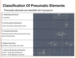
Pneumatic elements are classified into 5 groups as
5. Working elements
Air cylinders
4. Final control elements
Flow control valve, Quick exhaust valve
3. Control elements
Directional control valves like solenoid valves,
pilot operated valves
2. Signal elements
Push button valve, Roller lever valve
1. Source & Service elements
Source – Compressor & Reservoir
Service – Filter, Regulator, Lubricator
2. 1. Source & Service elements
1. Air
2. Compressor
3. Air Filter
4. Air Pressure Regulator
5. Air Lubricator
6. Air Service Unit
7. Pneumatic Silencer
3. Air
The earth is surrounded by an envelope of air known as atmosphere.
The composition of this 12 mile thick envelope. Due to the
compressibility of air, increasing the pressure causes decrease in the
volume of air.
Boyles Law: - Boyle discovered that the pressure and the volume of a
particular quantity of gas was constant provided that the temperature
did not vary.
8. Compressors
A compressor is a machine that compresses air or another
type of gas from a low inlet pressure (usually atmospheric) to
a higher desired pressure level. This is accomplished by
reducing the volume of the gas. Air compressors are generally
positive displacement units and are either of the reciprocating
piston type or the rotary screw or rotary vane types.
Graphic symbol
9. Types of compressor
• Piston Compressor
In this type of compressor a cylinder bore
encloses a moving piston. As the
crankshaft of the compressor rotate, the
piston moves within the cylinder, similar
to the piston in a car engine. As the
piston is pulled down, the volume
increases, creating a lower atmospheric
pressure in the piston chamber. This
difference in pressure causes air to
enter via the inlet valve. As the piston is
forced upwards the volume of air
reduces. The air pressure therefore
increases. Eventually the pressure
forces the outlet valve to open.
10. • Vane Compressor
The following figure shows a cutaway view of the sliding-vane-type rotary
compressor. The air inlet is placed where the volume of the
compression chamber is greatest, the outlet where the volume is
smallest. Consequently, as the vanes turn, the space between them is
reduced. This reduction in volume compresses the air as it travels from
the inlet to the outlet.
11. • Screw compressor
There is a current toward increased use of the rotary-type
compressor due to technological advances, which have produced
stronger materials and better manufacturing process. The
following figure shows a cutaway view of a single-stage screw
type compressor. Precise positioning of the screw is essential for
its performance. Oil provides a seal between the rotating screws
as well as lubricating the parts and cooling the air. The oil is then
separated from the air before it enters the system.
12. • Lobe compressor
In this type of compressor the rotors do not touch and
certain amount of slip exists. This slip increases as the
output pressure increases. It is therefore operated at
maximum speed for the highest efficiency. 17.3 bar is
obtainable with this type of constant displacement
compressor.
Inlet
Outlet
13. Compressor Specification
Input volume of
air in liter/min
Input volume of
air in
cubic foot/min
Input voltage
in volt
Input frequency
in Hertz (Hz)
Input current
in Amp.
Output power in
Horse power (HP)
Output power in
Kilowatt (KW)
Rotating speed
of crankshaft in
revolution per
minute (rpm)
Output
pressure in bar
Output pressure
in pounds per
square inch (PSI)
Loudness of
output sound in
decibel (DB)
14. Air Filter
The air needs to be filtered to be free of moisture and contamination. Air filter is used to do this job.
The filter elements remove the particles and moisture as small as 5 microns. Normally 30-50
micron filter is used in pneumatic system.
Graphic symbol
15. Air pressure regulator
The pressure regulator is used to adjust the desired pressure for the pneumatic system. This use a
piston to sense downstream pressure fluctuations. The piston, in turn, works against a set spring
pressure. As the pressure downstream drops it is sensed by the diaphragm and the poppet valve
opens. This adjusts the position of the poppet valve, which limits the downstream pressure to the
pre-set valve.
Graphic symbol
16. Air lubricator
A lubricator ensures proper lubrication of internal moving parts pneumatics components. The
proportional increase in oil mist by an increase of air flow is achieved by the spring loaded poppet
assembly. As the flow increases and the valve opens, the area is increased and a pressure
differential created.
Graphic symbol
17. Air service unit
Filters, regulators and lubricators can be combined to ensure optimum compressed air preparation
for a specific pneumatic system.
Graphic symbol
18. Pneumatic Silencer
To decrease the noise of air in the outlet of valves, a silencer can be used. They are made from
the porous plastic or bronze. Some of them are equipped with a control flow valve to control
velocity of flow in the outlet of valves as well.
Graphic symbol
19. 2) SIGNAL ELEMENTS
General manual
Push button
Pull button
Push/pull button
Lever
Pedal
Treadle
Manually Operated
Rotary knob
21. Solenoid direct
Solenoid pilot
Solenoid pilot
with manual override and
integral pilot supply
Electrically Operated
Solenoid pilot with
manual override and
external pilot supply
When no integral or
external pilot supply is
shown it is assumed to
be integral
22. 3) Direction Control Elements
2/2 Direction control valve
3/2 Direction control valve
4/2 Direction control valve
5/2 Direction control valve
5/3 Direction control valve
Port & Position.mp4
23. Basically a valve is named in
the following order
1. No. of positions
2. No. of ports
1. No. of positions
No. of positions
2 position
3 position
Graphic symbol
1 2
1 2 3
24. 2. No. of ports Symbol
2 ports
3 ports
4 ports
5 ports
25. 1 3
4 2
5
Working ports
Symbols for valve actuations are
shown at the left hand side or
right hand side only
The lines drawn on the outside
of the square in the normal or
initial position represent the
ports
Exhaust
ports
Pressure
ports
Switching positions are shown
by squares and are drawn
adjacent to each other
Line with arrow represents
direction of flow. Shut-off
position is shown by T.
Normal position is the
switching position when the
valve is not actuated
GRAPHIC REPRESENTATION
26. Function 2/2
Normal position
Basic valves before
operators are added
Examples, push button operated
with spring return
2/2 DIRECTION CONTROL VALVE
27. Function 2/2
Operated position
Basic valves before
operators are added
Examples, push button operated
with spring return
2/2 DIRECTION CONTROL VALVE
28. Function 3/2
Normal position
Basic valves before
operators are added
Examples, push button operated
with spring return
3/2 DIRECTION CONTROL VALVE
29. Function 3/2
Operated position
Basic valves before
operators are added
Examples, push button operated
with spring return
3/2 DIRECTION CONTROL VALVE
30. Function 4/2
Normal position
Basic valves before
operators are added
Examples, push button operated
with spring return
4/2 DIRECTION CONTROL VALVE
31. Function 4/2
Operated position
Basic valves before
operators are added
Examples, push button operated
with spring return
4/2 DIRECTION CONTROL VALVE
32. Function 5/2
Normal position
Basic valves before
operators are added
Examples, push button operated
with spring return
5/2 DIRECTION CONTROL VALVE
33. Function 5/2
Operated position
Basic valves before
operators are added
Examples, push button operated
with spring return
5/2 DIRECTION CONTROL VALVE
34. Three position valves have a normal central
position that is set by springs or with a manual
control such as a lever
The flow pattern in the centre position varies
with the type. Three types will be considered
1, All ports sealed
2, Outlets to exhaust, supply sealed
3, Supply to both outlets, exhausts sealed
5/3 DIRECTION CONTROL VALVE
35. All valves types shown in the normal position
Type 1. All ports sealed
Type 2. Outlets to exhaust
Type 3. Supply to outlets
5/3 DIRECTION CONTROL VALVE
36. All valves types shown in the first operated position
Type 1. All ports sealed
Type 2. Outlets to exhaust
Type 3. Supply to outlets
5/3 DIRECTION CONTROL VALVE
37. All valves types shown in the normal position
Type 1. All ports sealed
Type 2. Outlets to exhaust
Type 3. Supply to outlets
5/3 DIRECTION CONTROL VALVE
38. All valves types shown in the second operated position
Type 1. All ports sealed
Type 2. Outlets to exhaust
Type 3. Supply to outlets
5/3 DIRECTION CONTROL VALVE
39. 4) FINAL CONTROL ELEMENTS
(Flow control valve)
Throttle valve
Graphic symbol
44. LOGIC “OR” SHUTTLE VALVE
A
C
B
A
C
B
A B
Input Output
A B C
OFF OFF OFF
ON OFF ON
OFF ON ON
ON ON ON
Graphic symbol
C
has two The OR logic valve
inputs and one output.
The output is ON if one or two
inputs are ON
And the output is OFF only if all
outputs are OFF.
45. LOGIC “AND” SHUTTLE VALVE
The AND logic valve has two
inputs and one output.
The output is ON only if all two
inputs are ON
And the output is OFF if one or
more inputs are OFF.
A
C
B A B
C
A
C
B A B
C
C
A B
Popular old
symbol
C
A B
ISO 1219-1
symbol
Input Output
A B C
OFF OFF OFF
ON OFF OFF
OFF ON OFF
ON ON ON
Graphic symbol