1. How to overcome roof guttering -A case study
*
B. Ramesh Kumar CGM (CP&P ** MD. Suresh Kumar, Addl Mgr (Mech.Cell)
1. Introduction
Guttering is one of the critical roof failures in underground drivage. Initially it creates
tensional cracks and on later stage, it develops into a groove or cut along the sides of the
drivage. These tensional cracks if not promptly supported, interact with weak planes in the
upper horizons, extend to the entire gallery, lead to heavy roof dilation and finally end in
ar
roof collapse. Occurrence of gutter roof is always unsafe as it brings instability in the roof
condition thereby it requires heavy secondary supporting and become production constraint
um
too.
Lot of research was carried out on this issue and is still being continued all around the
world. It is widely accepted that guttering occurs due to intersection of a roadway drivage
hK
with the horizontal stress domain at an angle. The effect of guttering depends on the
magnitude of horizontal stress. Frith (2002) noted that in most situations guttering is a
result of high horizontal stresses. Van der Merwe and Madden (2002) of South Africa
acknowledged that the occurrence of guttering in coal mines is stress related. However,
res
Van der Merwe and Peng (2000) had earlier argued that the role of horizontal stress is
being exaggerated in roof instability in coal mines. It is proved that the direction of mining
parallel to the direction of horizontal stress has shown little impact or no impact on roof
.Su
condition whereas a drivage intersecting the direction of horizontal stress domain is
subjected to gutter roof. The magnitude of gutter depends on the angle of intersection of
drivage, compressive and tensile strength of the coal, magnitude of horizontal stress,
presence of weaker planes and clay and the depth of mining.
MD
2. Adriyala Longwall Project
or:
Adriyala Longwall Project (ALP) is a prestigious project of the SCCL, as designed first-
ever high productive Longwall face in India. Presently, there are four ‘DOSCO’ machines
driving entries and gate roads in No.1 seam. Amongst them, three are driving trunk
th
roadways from Punch entries opened from highwall of OC-II and the other one is driving
top gate of Longwall Panel No.1 from Gdk10A dip side. The dimensions of the drivage are
Au
5.5m widthx3.6m height to enable the movement of free steered vehicles (FSVs). The
general horizontal stress direction in the Adriyala property lies N 22o E whereas the
Adriyala road ways are intersecting at an angle of nearly 45 o to it. The ratio of major to
minor horizontal stress is 1:1.3.
3. Definition of the Problem
In order to develop LWP-1 of the Adriyala property in time, it was planned to drive top
gate of LWP-1 from Gdk-10A dip side. Therefore, a dip gallery has been driven from dip
side top section working of Gdk-10A to enter into to top gate middle section of No.1 seam.
The thickness of No.1 seam is around 6.0m in which the gate roads are developed in
bottom section leaving coal and clay in the top. During the drivage of this top gate, roof
2. problems were encountered continuously due to guttering along dip side in the roof. So the
immediate coal layers readily buckled and fractured for a depth of 20cm to 50cm and
continued to part and fall down after exposure. Presence of slips ratified the damage due to
guttering and resulted in roof fall of 0.4m to 0.6m at few places. The first 60m of the
gallery was bolted with cement grout and the rest with resin grout. Bolting was done in
conjunction with wire mesh and w-straps. The secondary supports like roof stitching and
horizontal steel girders were fixed in the gallery. Guttering problem were faced during
drivage of gate roads in earlier strike panels and dip rise panels also in Gdk-10A.
4. Condition of roof along top gate
ar
At two places, minor falsl upto the height of 0.4m– 0.6m, for the length of 1–1.2m length
and for the full width of the gallery were recorded. The face has progressed for about 100m
um
as on 28.04.2010. Uniformity in the cutting profile (along ribs) was not achieved with
‘DOSCO’ machine and it warranted further training of operators. The side profile was
varying for every cut. Clay thickness in the roof increased to 0.4m from 0.2m between
67m–100m, where height of extraction also increased to 3.8m – 4.0m. As a result of
hK
guttering, the condition of roof was deteriorated for the first 60m, where roof bolting was
done using cement capsules. In this zone, the cracks due to guttering along dip side
extended upto center of the gallery and even upto rise side at few places. Water started
res
percolating from the cracks.
Between 60-100m where bolting was done using resin grout, the condition of roof was just
better than that of first 60m. Guttering continued in the resin bolted zone also ie. between
.Su
60-100m. It was reported that, due to guttering, roof layers became weak within few
minutes after exposure and roof layers upto 0.5m got crumbled and collapsed immediately
after cutting and before bolting could be done. Thus the roof profile was no where uniform
between dip and rise sides upto 100m of the face progress.
MD
5. Bolting Practice at DOSCO face
5.1. Bolting design
th or:
Au
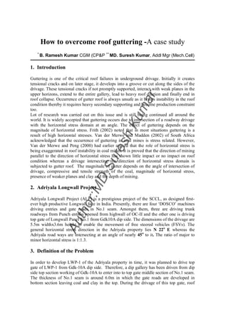
Fig: Support design for Adriyala Gate roadways
Bolting pattern was designed by CIMFR using bore hole data and RMR (Rock Mass
Rating) calculations. As per the design, the spacing between rows is 1.2m and between
3. bolts is 0.85m/ 0.9m leaving 0.45m at edges. Two bolts are in vertical direction and
remaining are angled bolts at 68o as shown in the figure. Three pieces of w-straps each
1.2m length are fixed against roof along with wire mesh. Such set up used to consume lot
of time for handling and setting of each piece. Time consumed for one cycle of bolting was
nearly 2 to 2.15 hours for setting one row of bolts with 3 Nos w-strap pieces with wire
mesh combinations. Strictly, there used to be an unsupported roof of 1–1.2m was
maintained from last support to face at any given time. It was observed that, guttering used
to take place within 10-15 minutes after roof was exposed. If dressed down, the parted
immediate layers happened to fall down and the upper layers used to be intact (to that time)
& sound good. It used to become weak later on behind the machine.
ar
5.2. Application of resin and other consumables
um
Two resin capsules of each 24mm dia x 450mm length, one fast set (maximum of 28
sec) at the top of the hole and a slow set (max 180 sec) were being used as grout
medium.
hK
The fast set capsules at the top of hole were not compatible with the crew’s experience
and the speed of bolting. Any small delay during the process of spinning, and thrusting
of bolt lead to setting of resin and hence the bolt couldn’t be further thrust into the hole
or given torque.
res
It was also observed that, at least 50% of the bolts were not set to the requirement as
the bearing plates were fixed in reverse direction, missing of torque nut (conical seat)
resulting in penetration of shear nut into bearing plate and insufficient application of
.Su
torque for pre-tension. In such places, the collar failure and shear failure were
experienced.
Design requires 1.8m roof thickness to be reinforced with 1.8m long bolts for vertical
holes and 2.1m long bolts for inclined holes which are angled at 68o.
MD
It was noticed that there was confusion amongst workmen. Some times only 1.8m bolts
are used for all the holes because of which the effective supporting height is reduced
below 1.8m in angled holes.
The length of drill rod was not matching with the length of bolts. Hence, a manual
or:
marking by shift crew was found mismatching with length of bolt some times. Such
mismatch generally doesn’t bring any difference in cement grout but when using resin,
th
high precision is required. The deep holes receive entire length of bolts while inserting
with rig at certain thrust. In the short holes, the bolts were protruding outward. Hence in
Au
the both the cases, pre-tensioning is not possible.
5.3. Drill rig and Torque for bolt tensioning
The DOSCO machine has been provided with two drill rigs along with timber jacks for
temporary roof hold. These rigs can not traverse but can be tilted to drill holes at
different angles in the same row.
It was noticed that the leakage in the circuit due to hose damage, and O- ring failures
etc., reduced the available torque to tension the bolt. Some times the pressure drop and
the loss of flow went unnoticed during operation.
This eventually reduced thrust and torque for pre-tension of the bolt, creating room for
layering due to guttering effect.
4. Unless the pump delivery pressure and the rate of flow is measured time to time, the
reduction of torque and thrust can not be generally noticed as the bolters are capable of
drilling, spinning and grouting the resin even at low pressure also. But it can not exert
full torque during pretension.
The break out nuts are designed for the torque range of 100-120Nm whereas the setting
load available at 500 rpm and pressure of 2500psi is nearly 160KN. So that much
available torque and thrust shall be utilised for effective pre-tension which would act
against the collar loading particularly where guttering is experienced.
6. Attempt for stabilising the roof condition
ar
Based on the past experience and state of art resin applications, the following decisions
were taken and improvements were done to stabilise the roof conditions.
um
6.1. Advance support
It was understood that the failure of roof is time dependent. Hence, it was planned to fix
**
hK
some advanced support like fore poling so that the Roof Response Time (RRT) of the
exposed roof could be increased. Fore poling was done by fixing steel bolts of lengths,
1.8m / 2.4m in the roof level, at an angle of 10-20 o (gently raising) with hand held drill
using cement capsules. The fore-polling continued in pre-shift to give cushioning to three
res
production shifts. The initial fore poling, has given allowance of more than 20 minutes time
for supporting without any symptom of guttering or cracks, after roof
.Su
**
Roof Response time/ Roof stand up time: Time taken between roof exposure
and first symptom of stress relief in the form of layering. Mark (1988 Australia):
For the first time, he has drawn up relationship of stand up time and roof failure for
MD
tunnel. Bieniawski (1989): quantified this relationship between RMR and the roof
stand up time. Molinda & Mark (1994 ASA) attempted to quantify roof response
time with respect to CMRR for US mines. Dr. JN. Van der Merve (SA) found that
redistribution of stress following the excavation is immediate, but the failure process
or:
is time dependent.
th
exposure. Such time was found sufficient to fix dip side bolts immediately. Once the roof
started holding, the RRT also increased.
Au
6.2. Reinforcement-W-straps of single unit instead of pieces
It was observed that the practice of fixing 3 Nos of pieces of each 1.2m w-straps were
extremely time consuming process. Hence, these pieces were replaced by w-straps of
length 4.8m to cover the entire width of the gallery to form a single beam. Holding the full
length mesh and w-strap together with the help of timber jack on either side was found
easier and simpler. The corner bolts were fixed first followed by the intermediate angled
bolts. Thus the manual handling of mesh and w-strap was reduced greatly and the time
taken for completing one cycle of roof support was reduced to 45 min.
6.3. Reduction of Spacing and increased bolt length
5. The spacing between each row of bolts was reduced to 1m instead of 1.2m as designed by
CIMFR. To avoid confusion amongst the crew, all the bolts both vertical and inclined were
made to uniform length of 2.1m.
6.4. Mono speed resin
In the dual speed resin system, the over heating by over spinning of resin column,
insufficient thrust by rig, delay in the bolt spinning and insufficient hold time often caused
acceleration of setting of top most fast set resin capsule. In such case, the bolts could not be
thrust further and were protruding outwards serving no useful purpose. Hence it was
decided to use only mono speed slow set resin of 150 sec which has given sufficient time to
ar
match with our crew’s expertise. The use of dual speed resin was deferred until the crew
gets sufficient practice.
um
6.5. Correct bolting procedure
The following care was taken while fixing the bolt such as:
hK
Correct hole depth to bolt length was maintained by welding stoppers in the drill rods.
Capsules and bolt were inserted with correct positionining and direction of bearing
plate and tongue nut.
res
Proper spinning of bolt in the resin column was done by maintaining correct spin time.
Required hold time was maintained for resin formation by chemical reaction.
After bolt insertion, spinning and hold time was over, a final thrust with full torque at
the rated pressure of 2000 psi was given to the bolts.
.Su
When pre-tension was applied (with torque to stall concept), the w-strap, conical shape
of the bearing plate got fully pressed against the roof creating effective stiffness and
setting load to the bolts.
MD
6.6. Health monitoring of drill rig and hydraulics
The output pressure and flow rate of the hydraulic pump was thoroughly checked, the
or:
leakages were arrested and awareness was brought to the tradesman about the importance
of pump pressure and flow rate for effective reinforcement.
th
7. Improvement achieved and monitoring of bolt performance
Au
The above system of bolting was continued from the face progress of 104m onwards.
Effect of guttering was minimized between 100-140m and face could be progressed
without guttering symptom there onwards.
Time for a bolting cycle was reduced to 45 minutes.
Bolting crew has started developing expertise and confidence in application of the roof
bolters.
Both the angled bolts and vertical bolts were giving equal load in pull test of 10 T
conducted within 10 minutes.
Average daily/ monthly progress was increased and the machine could achieve 150m
progress in a particular month.
8. Conclusion
6. As a general rule, guttering was not expected in the gate roadways of Adriyala Longwall
Project as the major to minor horizontal stress ratio is below 2. The factors like variation in
clay thickness, position of a sump over top gate of LWP-1 drivage and depth of working
might have supplemented damaging effect to the guttering. However, the phenomenon of
guttering was studied carefully and the required measures were taken including those
practicing correct procedure of bolting using resin grout and reinforcing the roof in the
quickest possible time. With these, the guttering was controlled and the general roof
condition was improved.
9. Recommendations
ar
The control achieved over gutter roof may be site specific. At the deeper horizons the
requirements may vary. Hence the following are recommended:
um
Light weight steel wired fiber mesh or steel mesh of 5m width and 1m length pieces
having higher tensile strength may be still convenient to reduce the cycle time of
bolting.
Day wise, shift wise health monitoring of hydraulic pump, circuits and torque generated
by bolter is to be done. hK
Pressure loss in the bolter head shall be treated as machine break down and the face
should not be exposed further which will be otherwise progressed with inefficient
res
bolting.
Secondary support such as cable bolting anchored in sand stone roof must follow
behind the machine.
.Su
References
1. Minova guide to Resin grouted rock bolts
MD
2. Control mechanism of a tensioned bolt system in the laminated roof with a large
horizontal stress : Song Guo, asst VP, John C.Stankus, VP, Jenmar corporation, PA
3. Developments in Long Tendon Systems Used In Coal Mining Reinforcement: Brian
Clifford, Senior Geotechnical Engineer , Lorraine Kent Geotechnical Engineer ,Peter
or:
Altounyan GM, Dave Bigby Manager, Instrumentation and Research, RMT UK
4. Variation in load transfer of a fully encapsulated rock bolt : PC Hagan, UNSW, Sydney
th
5. Performance of roof support under high Stress in a US coal mine : David Oyler and
Christopher Mark NIOSH Pittsburgh, PA, Winton Gale,SCT, NSW, Australia, Jinsheng
Au
Chen,RAG, PA
6. Status of roof bolting research at UNSW, Australia
7. Roof bolting and place change practices in coal mines, William S Mcintyre, Chief
Design Engineer, Jh Fletcher, Huntington, USA
8. Higher performance in rock-bolting technology by use of immediate-bearing grouted
bolts, Dipl.-Ing. Jürgen Wiegard And Dipl.-Ing. E.A. Eigemann, minova carbotech
GMBH
9. Rock support in Southern African hard rock mines. Dennis Van Heerden Minova RSA
10. Evaluating Development in Roof bolting Technology in Australian Coal Mining –DSI.
11. Field performance testing of fully grouted roof bolts, C. Mark, C. S. Compton, D. R.
Dolinar, D. C. Oyler, Natl. Inst. For Occuptnl. Sfty. & Health, Pittsburgh, PA.